EP2084111B1 - Verfahren und vorrichtung zur abschreckung geformter glasscheiben - Google Patents
Verfahren und vorrichtung zur abschreckung geformter glasscheiben Download PDFInfo
- Publication number
- EP2084111B1 EP2084111B1 EP07854737.9A EP07854737A EP2084111B1 EP 2084111 B1 EP2084111 B1 EP 2084111B1 EP 07854737 A EP07854737 A EP 07854737A EP 2084111 B1 EP2084111 B1 EP 2084111B1
- Authority
- EP
- European Patent Office
- Prior art keywords
- quench
- quenching
- formed glass
- pressures
- glass sheet
- Prior art date
- Legal status (The legal status is an assumption and is not a legal conclusion. Google has not performed a legal analysis and makes no representation as to the accuracy of the status listed.)
- Active
Links
Images


Classifications
-
- C—CHEMISTRY; METALLURGY
- C03—GLASS; MINERAL OR SLAG WOOL
- C03B—MANUFACTURE, SHAPING, OR SUPPLEMENTARY PROCESSES
- C03B27/00—Tempering or quenching glass products
-
- C—CHEMISTRY; METALLURGY
- C03—GLASS; MINERAL OR SLAG WOOL
- C03B—MANUFACTURE, SHAPING, OR SUPPLEMENTARY PROCESSES
- C03B27/00—Tempering or quenching glass products
- C03B27/04—Tempering or quenching glass products using gas
- C03B27/0404—Nozzles, blow heads, blowing units or their arrangements, specially adapted for flat or bent glass sheets
-
- C—CHEMISTRY; METALLURGY
- C03—GLASS; MINERAL OR SLAG WOOL
- C03B—MANUFACTURE, SHAPING, OR SUPPLEMENTARY PROCESSES
- C03B25/00—Annealing glass products
- C03B25/02—Annealing glass products in a discontinuous way
- C03B25/025—Glass sheets
-
- C—CHEMISTRY; METALLURGY
- C03—GLASS; MINERAL OR SLAG WOOL
- C03B—MANUFACTURE, SHAPING, OR SUPPLEMENTARY PROCESSES
- C03B27/00—Tempering or quenching glass products
- C03B27/04—Tempering or quenching glass products using gas
- C03B27/0413—Stresses, e.g. patterns, values or formulae for flat or bent glass sheets
-
- C—CHEMISTRY; METALLURGY
- C03—GLASS; MINERAL OR SLAG WOOL
- C03B—MANUFACTURE, SHAPING, OR SUPPLEMENTARY PROCESSES
- C03B27/00—Tempering or quenching glass products
- C03B27/04—Tempering or quenching glass products using gas
- C03B27/0417—Controlling or regulating for flat or bent glass sheets
-
- C—CHEMISTRY; METALLURGY
- C03—GLASS; MINERAL OR SLAG WOOL
- C03B—MANUFACTURE, SHAPING, OR SUPPLEMENTARY PROCESSES
- C03B27/00—Tempering or quenching glass products
- C03B27/04—Tempering or quenching glass products using gas
- C03B27/044—Tempering or quenching glass products using gas for flat or bent glass sheets being in a horizontal position
- C03B27/0442—Tempering or quenching glass products using gas for flat or bent glass sheets being in a horizontal position for bent glass sheets
- C03B27/0445—Tempering or quenching glass products using gas for flat or bent glass sheets being in a horizontal position for bent glass sheets the quench unit being adapted to the bend of the sheet
Definitions
- This invention relates to a method and apparatus for quenching formed glass sheets.
- Formed glass sheets are conventionally quenched to enhance their mechanical properties. Such formed glass sheets are conventionally used on vehicle side and back windows as well as in other applications such as architectural applications and food storage and display units, etc. Usually the forming and quenching is performed to provide tempering that provides the glass sheet with surface compression on the order of 100 MegaPascals (14,250 psi), but the quenching can also be utilized to perform heat strengthening wherein the surface compression is less such as on the order of 50 MegaPascals (7,250 psi).
- Conventional forming and quenching systems successively form and quench the glass sheets in a cyclical manner one after another initially at a forming station and then downstream at a quench station.
- the formed glass sheets can be formed and delivered from the forming station faster than quenching can be performed in the quench station such that reduction in the cycle time of the system is limited by the time of the quenching.
- Forced convection is conventionally utilized to perform glass sheet quenching in order to establish a temperature gradient between the glass surfaces and its center, starting from a tempering temperature on the order of about 645°C and cooling to the ambient.
- the glass surfaces Upon the glass sheet cooling to ambient temperature throughout its extent, the glass surfaces are in a state of compression and the glass center is in a state of tension.
- the surface compression resists breakage so as to provide mechanical strength to the quenched glass.
- the extent of the center tension and accompanying surface compression is often measured by the glass break pattern, specifically by counting the number of broken pieces in a number of confined areas, usually by counting each full broken piece as one and each partial piece as one-half and then adding to provide a total. A greater number indicates a greater resistance to breakage.
- the surface stress should not be too great so that the glass breaks into pieces that are too small.
- An object of the present invention is to provide an improved method to reduce glass sheet quench processing time.
- the method for quenching formed glass sheets in accordance with the invention is performed by moving a formed glass sheet that is heated to a quenching temperature into a quench to between lower and upper quench heads that are operable to supply upward and downward gas flows for quenching the formed glass sheet.
- Upward and downward gas flows are initially supplied through the lower and upper quench heads for about 0.5 to 1.3 seconds at initial pressures to quench the formed glass sheet.
- This initial pressure quenching uses conventional quench pressures.
- the upward and downward gas flow pressures are increased through the lower and upper quench heads for .5 to 4 seconds to pressures at least 25% higher than the initial pressures to further quench the formed glass sheet.
- the increased pressure quenching is disclosed as being provided by pressures at least 50% greater than the initial quench pressure, specifically with pressures 50 to 100% greater than the initial quench pressures.
- the finally mentioned quenching has a decreased cooling power that is no greater than 75% of the cooling power provided by the initial pressure quenching and that is preferably no greater than 60% and most preferably about 50% of the cooling power provided by the initial pressure quenching.
- the finally mentioned quenching has a decreased cooling power that is preferably no greater than the 80% of the cooling power provided by the quench at minimum conventional quench pressures and that is more preferably no greater than 70% and most preferably about 60% of the cooling power provided by the quench at minimum conventional quench pressures.
- the increased pressure quenching is preferably provided by pressures 50 to 100% greater than the initial pressure quenching, and the finally mentioned quenching has a decreased cooling power that is no greater than 60% of the cooling power provided by the initial pressure quenching and no greater than 70% of the cooling power provided by the quench at minimum conventional quench pressures when the initial cooling is with conventional quench pressures.
- the quench (a) is initially in an open position to receive the formed glass sheet between the quench heads; (b) is then moved to a closed position to perform the initial and increased pressure quenching; and (c) is then moved back to the open position to permit delivery of the formed glass sheet in preparation for the next cycle.
- the decreased cooling power quenching is performed at least to some extent within the quench.
- the formed glass sheet is disclosed as being moved to an aftercooler to perform at least to some extent the decreased cooling power quenching. More specifically, the decreased cooling power quenching is disclosed as being partially performed within the quench and the formed glass sheet is then moved to the aftercooler to perform further decreased cooling power quenching.
- the formed glass sheet is supported on a quench ring for movement into the quench and is also supported on the quench ring during the initial and increased pressure quenching between the lower and upper quench heads.
- the formed glass sheet is moved out of the quench on the quench ring.
- the formed glass sheet is lifted upwardly off the quench ring within the quench for subsequent delivery from the quench. In the latter method, the upward gas flow forces the formed glass sheet upwardly against a transfer device for movement out of the quench.
- Another object of the present invention is to provide improved apparatus for quenching glass sheets.
- the apparatus for quenching glass sheets in accordance with the invention includes a quench system having a quench including lower and upper quench heads that are operable to supply upward and downward gas flows that can be at conventional quench pressures.
- a quench ring of the apparatus positions a heated and formed glass sheet between the quench heads for quenching.
- a control of the apparatus operates the quench to initially supply through the lower and upper quench heads upward and downward gas flows for about 0.5 to 1.3 seconds to quench the formed glass sheet. The control then operates the quench to increase the upward and downward gas flow pressures through the lower and upper quench heads to at least 25 % greater than the initial pressures for .5 to 4 seconds.
- the control thereafter operates the quench system to continue to supply upward and downward gas flows to the formed glass sheet with decreased cooling power that is less than the cooling power of the initial pressure quenching to eventually provide a tempered and formed glass sheet upon cooling throughout to ambient temperature.
- the initial quenching is at conventional quench pressures
- the last mentioned cooling has cooling power that is less than the cooling power of the quench at minimum conventional quench pressures.
- the quench of the apparatus includes quench heads that are movable between an open position where the formed glass sheet is transferred into and out of the quench and a closed position in which the initial pressure and increased pressure quenching are performed.
- a quench ring of the apparatus transfers the heated and formed glass sheet into the open quench and supports the formed glass sheet during the initial pressure and increased pressure quenching.
- the apparatus also includes an aftercooler and in one embodiment the quench ring moves the formed glass sheet from the open quench to the aftercooler for at least part of the decreased cooling power quenching.
- a transfer device of another embodiment receives the formed glass sheet from the quench ring to provide transfer thereof from the open quench to the aftercooler.
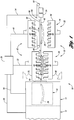
- a glass sheet forming and quenching system is generally indicated by 10 and includes a partially illustrated furnace 12 for heating glass sheets to a forming and quenching temperature, a bending station 14 that includes bending apparatus 16 for cyclically forming glass sheets one after another and a quench system collectively indicated by 18.
- the quench system 18 includes a quench 20 constructed in accordance with the invention to perform a quenching method of the invention as is hereinafter more fully described, and the quench system also includes an exit cooling station 22 having an aftercooler 24 for continuing forced convection cooling of formed glass sheets as described below.
- a central control 26 includes: control connections 28 and 30 respectively to the furnace 12 and the bending station 14; control connections 32 and 34 to the quench 20 and an actuator 36 for a quench ring 38 that moves between the bending station 14, the quench 20 and the cooling station 22; and a control connection 40 that operates the aftercooler 24 of the cooling station 22.
- the quench system 18 includes apparatus collectively indicted by 42 for performing quenching in a manner that reduces the time required in the quench in order to reduce the overall cycle time of the system in successively forming and quenching glass sheets for delivery.
- the quench apparatus 42 and method of the invention for quenching formed glass sheets will be described in an integrated manner to facilitate an understanding of all aspects of the invention.
- the furnace 12 and bending station 14 may be constructed in any conventional manner but are preferably constructed in accordance with the disclosure of United States Patent Application Serial No. 11/255,531 of Vild et al. which was filed on October 31, 2005, assigned to the assignee of the present invention.
- the bending station 14 includes a door 44 that is opened and closed to permit the quench ring 38 to be moved by the actuator 36 through a connection 46 into the bending station to receive a formed glass sheet G in preparation for cooling of the glass sheet.
- the quench 20 of the quench system 18 includes lower and upper quench heads 48 and 50 that have the general shape of the glass sheet to be quenched and that are movable between a phantom line partially illustrated open position and the full solid line indicated closed position.
- the lower and upper quench heads 48 and 50 of the quench are in the open position and are then closed to commence the quenching.
- the lower and upper quench heads 48 and 50 respectively then provide upward and downward gas flows 52 and 54 that perform the quenching as is hereinafter more fully described.
- the quench 20 is moved to its open position and the actuator 36 moves the quench ring 38 to the cooling station 22 into the aftercooler 24 between its lower and upper cooling heads 56 and 58 that supply upward and downward cooling gas flows 60 and 62 but at pressures that provide lesser cooling power than prior quenching in the quench 20 as is more fully described below.
- the pressure of the upward gas flows 60 is subsequently increased to lift the glass sheet from the quench ring 38 upwardly against a transfer device 64 which is illustrated as a conveyor having a conveying loop 66 extending around wheels 68 at least one of which is rotatively driven to move the lower reach of the conveying loop in the direction shown by arrow 70 so the glass sheet is moved toward the right for further cooling and delivery.
- a transfer device 64 which is illustrated as a conveyor having a conveying loop 66 extending around wheels 68 at least one of which is rotatively driven to move the lower reach of the conveying loop in the direction shown by arrow 70 so the glass sheet is moved toward the right for further cooling and delivery.
- the actuator 36 moves the quench ring 38 back through the open quench 20 to the bending apparatus 16 of the bending station 14 to receive another formed glass sheet for subsequent movement back toward the right into the quench 20 in preparation for commencing the next cycle.
- a transfer device 72 includes an extractor 74 that is moved by an actuator 76 under the control of a connection 78 to the central system control (not shown in this view) so as to provide coordination with the rest of the system.
- the pressures of the upward and downward gas flows 52 and 54 are modified to lift the glass sheet upwardly from the quench ring 38 against the extractor 74 of the transfer device 72.
- Actuator 76 then moves the extractor 74 and the glass sheet toward the right to the aftercooler 24 between its lower and upper cooling heads 56 and 58 whose upward and downward gas flows 60 and 62 are then at pressures that initially maintain the glass sheet upwardly against the extractor as additional cooling is provided.
- the pressures of the upward and downward gas flows 60 and 62 are then modified so that the glass sheet is released downwardly from the extractor 74 onto a lower conveyor 80 on an upper reach of a conveying loop 82 thereof which extends over wheels 84 at least one of which is rotatively driven to move the glass sheet toward the right as shown by arrow 86 for delivery.
- the quench ring 38 is moved toward the left by its actuator 36 back to the bending apparatus of the bending station to receive another formed glass sheet in preparation for subsequent movement back to the quench 20 to commence the next cycle.
- forced convection is conventionally utilized to perform glass sheet quenching in order to establish a temperature gradient between the glass surfaces and its center, starting from a tempering temperature of about 645°C and cooling to the ambient temperature.
- glass at ambient temperature acts much like a solid, it is actually a highly viscous liquid since glass is amorphous without any crystalline structure.
- the outer glass surfaces upon initial quenching are cooled and temporarily tensioned for about one second or more. This tension results from greater contraction of the glass outer surfaces as they are initially cooled faster than the glass center which is cooled slower and thus contracts less.
- the glass surface tension subsequently reduces as the thermal gradient between the cooler glass surfaces and the hotter glass center stops increasing and the stresses partially relax due to flow within the glass.
- the glass After the glass cools down to a temperature referred to as the "strain point", that is normally approximately 520°C (964°F), the glass becomes more viscous and does not move as fast as when it was hotter so relative flow between inner and outer layers is arrested and stress created by thermal contraction differences between layers can no longer be relaxed with time by flow in the glass.
- the glass center is hotter than the surfaces upon cooling through the strain point temperature. As such, upon the entire glass sheet reaching ambient temperature, the center has cooled through a greater temperature differential and contracted more than the surfaces so the center goes into tension and consequently forces the surfaces into compression.
- the surface compression as previously mentioned resists breakage so as to provide increased mechanical strength to the quenched glass.
- Figure 3 is a graph that illustrates the quench pressures utilized to perform the quenching in accordance with the present invention versus time and is comparable to the prior art graph illustrated in Figure 4 which shows that the quenching previously has required a much longer high pressure quench time which increases the cycle time of the entire system.
- the pressures illustrated will vary depending upon the glass thickness, quench construction and compressive surface tension desired such that the specific values shown are for purposes of illustration only.
- conventional quenching uses a constant quench pressure versus time of about 25 inches (63.5 cm) of water column for eight seconds or so to perform quenching that provides an acceptable break pattern for 3.8 mm thick glass.
- the break pattern or, more precisely, a count of the number of particles within a specified area of the broken glass surface is the standard way of determining the extent of the center tension in the glass and the accompanying surface compression. That entire eight seconds or so must be performed within the quench 20 so that when added to the time of the quench ring movements between the bending station and quench station, or between the bending station, quench station and cooling station, will require a cycle time on the order of about 13 seconds or more.
- the present invention as described below in connection with Figure 3 allows a reduction in the time while still providing an equivalent break pattern.
- the extent of quenching is measured by the resultant break pattern.
- quenching is controlled so that the break pattern satisfies recognized standards to assure glass strength and stresses that provide resistance to breakage.
- One widely recognized standard is the European Standard identified as ECE R43, which specifies that upon breakage square areas with 5 cm. sides located anywhere on the surface of the broken glass shall have a minimum particle count of no less than 40 and a maximum particle count no greater than 400. This particle count is provided by counting each particle fully within the square as one and each particle partially within the square as one half and then adding to sum the total.
- the tempered and formed glass sheets are normally tested by breaking in more than one location since the location of the nucleus of the breaking can affect the particle count.
- the extent of quenching power for providing formed glass sheets with acceptable temper levels depends on many factors including glass thickness and temperature upon initial quenching, the number of quench nozzle openings for a given area, the spacing of the nozzle openings with respect to each other, the size of the nozzle openings, the proximity of the nozzle opening outlets to the adjacent glass surface, the angles of incidence of the quench jets upon impinging with the glass surface, the pressure of the nozzle jets, the velocity of the nozzle jet flows, and the time length of the quenching, etc. For any given quench and formed glass sheet being quenched, there is a range of pressures that will provide the required effect to meet recognized break pattern standards.
- inventional quench pressure is any pressure in the range of pressures that when applied in the "conventional" constant pressure method for 10 seconds from a specific quench to a specific formed glass sheet heated to a specific quenching temperature will produce a tempered glass sheet upon eventual cooling throughout which when broken provides a break pattern with maximum and minimum particle counts that meet the European Standard ECE R43.
- the conventional quench pressures both upward and downward, will have both minimum pressures and maximum pressures that will provide quenching that will produce tempered and formed glass sheets meeting the applicable standard.
- the cooling power during quenching is the measure of the heat flow rate per area produced for each degree of temperature difference between the glass and the quenching gases provided by a set of quench factors as described above. When all other factors remain the same, the cooling power increases as the quench pressure increases, and the cooling power decreases as the nozzle to glass spacing increases.
- the heat transfer coefficient is measured in calories per second per square centimeter per degree Centigrade.
- the present invention provides quenching of a glass sheet that is immediately increased to a conventional pressure for about .5 to 1.3 seconds and as shown in Figure 5 maintains the temporary glass sheet surface tension in the range of about 14 to 20 MegaPascals, below which range there is insufficient quenching and above which range glass fracture is more likely during the quenching. Then, before the maximum temporary glass surface tension substantially decreases, such as at location 88 shown in Figure 5 , the upward and downwardly gas flow pressures at the quench 20 are increased at least 25% through the associated lower and upper quench heads from the initial pressures.
- the increased pressure quenching is performed for 0.5 seconds to 4 seconds with pressures greater than 50% of the initial pressures and most preferably in the range of 50 to 100% greater than the initial pressures. Thereafter, the upward and downward gas flows to the formed glass sheet are continued at pressures that provide less cooling power than the initial pressures as shown in Figure 3 .
- This decreased cooling is initially provided within the quench 20 and thereafter within the aftercooler 24 of the cooling station 22 as previously described.
- this decreased quenching is performed with upward and downward gas flows that provide a decreased cooling power that is no greater than 75% of the cooling power of the initial pressure quenching, preferably no greater than 60% of the cooling power of the initial pressure quenching, and most preferably about 50% of the cooling power provided by the initial pressure quenching.
- initial conventional quench pressures i.e. those that will produce glass with a break pattern having particle counts that will meet European Standard ECE R43 when continued for about 10 seconds
- the decreased cooling power quench is less than the cooling power provided by the quench at minimum conventional quench pressures. More specifically the decreased cooling is then no greater than 80%, preferably less than 70% and most preferably about 60% of the cooling power provided by the quench at minimum conventional quench pressures.
- glass temperature at the start of quenching was 643 degrees C.
- quench pressure started at 25 inches of H 2 O for .7 seconds, was then increased to 40 inches of H 2 O for 3.8 seconds and was then decreased to 6 inches of H 2 O for 3.5 seconds, as in Figure 3 .
- the break pattern yielded a central particle count of 227 pieces in a 5 x 5 cm square from a break point in the driver's side lower corner. So, the time required to be in the high pressure quench was reduced from 8.0 to 4.5 seconds.
Landscapes
- Chemical & Material Sciences (AREA)
- Physics & Mathematics (AREA)
- Engineering & Computer Science (AREA)
- Materials Engineering (AREA)
- Organic Chemistry (AREA)
- Thermal Sciences (AREA)
- Mathematical Physics (AREA)
- Re-Forming, After-Treatment, Cutting And Transporting Of Glass Products (AREA)
Claims (14)
- Verfahren zum Abschrecken geformter Glasscheiben, umfassend:Bewegen einer geformten Glasscheibe, die auf eine Abschrecktemperatur erhitzt wird, in einen Abschrecker zwischen untere und obere Abschreckköpfe, die so betrieben werden können, dass sie Gasströme nach oben und nach unten zum Abschrecken der geformten Glasscheibe zuführen können;initiales Zuführen von Gasströmen nach oben und nach unten durch die unteren und oberen Abschreckköpfe über etwa 0,5 bis 1,3 Sekunden auf initialen konventionellen Abschreckdruckwerten, um die geformte Glasscheibe abzuschrecken;danach Erhöhen der Druckwerte der Gasströme nach oben und nach unten durch die unteren und oberen Abschreckköpfe über 0,5 bis 4 Sekunden auf Druckwerte, die mindestens 25% höher sind als die initialen konventionellen Abschreckdruckwerte, um die geformte Glasscheibe weiter abzuschrecken; unddanach Zuführen der Gasströme nach oben und nach unten an die geformte Glasplatte mit verringerter Kühlleistung, die geringer ist als die durch den Abschrecker auf den konventionellen Mindestdruckwerten bereitgestellte Kühlleistung, um letztendlich nach dem durchgängigen Abkühlen auf Umgebungstemperatur eine gehärtete und geformte Glasscheibe bereitzustellen.
- Verfahren zum Abschrecken geformter Glasscheiben nach Anspruch 1, wobei das Abschrecken mit erhöhtem Druck bereitgestellt wird durch Druckwerte, die mindestens 50% höher sind als die initialen konventionellen Abschreckdruckwerte.
- Verfahren zum Abschrecken geformter Glasscheiben nach Anspruch 1, wobei das Abschrecken mit erhöhtem Druck durch Druckwerte bereitgestellt wird, die um 50 bis 100% höher sind als die initialen konventionellen Abschreckdruckwerte.
- Verfahren zum Abschrecken geformter Glasscheiben nach Anspruch 1, wobei die zuletzt genannten Gasströme nach oben und nach unten eine verringerte Kühlleistung aufweisen, die nicht größer ist als 80% der durch den Abschrecker auf den konventionellen Mindestdruckwerten bereitgestellten Kühlleistung.
- Verfahren zum Abschrecken geformter Glasscheiben nach Anspruch 1, wobei die zuletzt genannten Gasströme nach oben und nach unten eine verringerte Kühlleistung aufweisen, die nicht größer ist als 70% der durch den Abschrecker auf den konventionellen Mindestdruckwerten bereitgestellten Kühlleistung.
- Verfahren zum Abschrecken geformter Glasscheiben nach Anspruch 1, wobei die zuletzt genannten Gasströme nach oben und nach unten eine verringerte Kühlleistung aufweisen, die etwa 60% der durch den Abschrecker auf den konventionellen Mindestdruckwerten bereitgestellten Kühlleistung entspricht.
- Verfahren zum Abschrecken geformter Glasscheiben nach Anspruch 1, wobei das Abschrecken mit erhöhtem Druck durch Druckwerte bereitgestellt wird, die um 50 bis 100% höher sind als die initialen konventionellen Abschreckdruckwerte, und wobei die zuletzt genannten Gasströme nach oben und nach unten eine verringerte Kühlleistung aufweisen, die nicht größer ist als 70% der durch den Abschrecker auf den konventionellen Mindestdruckwerten bereitgestellten Kühlleistung.
- Verfahren zum Abschrecken geformter Glasscheiben nach Anspruch 1, wobei der Abschrecker: (a) sich anfänglich in einer offenen Stellung zur Aufnahme der geformten Glasscheibe zwischen den Abschreckköpfen befindet; (b) danach an eine geschlossene Stellung bewegt wird, um das initiale Abschrecken und das Abschrecken bei erhöhtem Druckwert auszuführen; und (c) danach zurück an die offene Stellung bewegt wird, um die Zufuhr der geformten Glasscheibe zur Vorbereitung auf den nächsten Zyklus zu ermöglichen.
- Verfahren zum Abschrecken geformter Glasscheiben nach Anspruch 8, wobei die zuletzt genannten Gasströme nach oben und nach unten mit verringerter Kühlleistung wenigstens in gewissem Maße in dem Abschrecker bereitgestellt werden.
- Verfahren zum Abschrecken geformter Glasscheiben nach Anspruch 8, wobei nach dem initialen Abschrecken und dem Abschrecken bei erhöhtem Druckwert die geformte Glasscheibe zu einem Nachkühler bewegt wird, wo die zuletzt genannten Gasströme nach oben und nach unten mit verringerter Kühlleistung zumindest in gewissem Maße ausgeführt werden.
- Verfahren zum Abschrecken geformter Glasscheiben nach Anspruch 8, wobei die zuletzt genannten Gasströme nach oben und nach unten teilweise in dem Abschrecker bereitgestellt werden, und wobei die geformte Glasscheibe danach zu einem Nachkühler bewegt wird, der weitere Gasströme nach oben und nach unten mit verringerter Kühlleistung bereitstellt.
- Verfahren zum Abschrecken geformter Glasscheiben nach Anspruch 1, wobei die geformte Glasscheibe auf einem Abschreckring zur Bewegung in den Abschrecker getragen wird, und wobei sie ferner durch den Abschreckring während dem initialen Abschrecken und dem Abschrecken bei erhöhtem Druckwert zwischen den unteren und oberen Abschreckköpfen getragen wird.
- Verfahren zum Abschrecken geformter Glasscheiben nach Anspruch 12, wobei die geformte Glasscheibe ferner auf dem Abschreckring aus dem Abschrecker heraus bewegt wird.
- Vorrichtung zum Abschrecken geformter Glasscheiben, umfassend:ein Abschrecksystem mit einem Abschrecker mit unteren und oberen Abschreckköpfen, die so betriebsfähig sind, dass sie Gasströme nach oben und nach unten zuführen;einen Abschreckring zur Positionierung der erhitzten und geformten Glasscheibe zum Abschrecken zwischen den Abschreckköpfen;eine Steuereinheit, die den Abschrecker betreibt, um anfänglich durch die unteren und oberen Abschreckköpfe Gasströme nach oben und nach unten mit initialen konventionellen Abschreckdruckwerten über etwa 0,5 bis 1,3 Sekunden zum Abschrecken der geformten Glasscheibe zuzuführen;wobei die Steuereinheit ferner die Druckwerte der Gasströme nach oben und nach unten für 0,5 bis 4 Sekunden durch die unteren und oberen Abschreckköpfe auf mindestens 25% mehr als die initialen konventionellen Abschreckdruckwerte erhöhen kann; undwobei die Steuereinheit danach das Abschrecksystem so betreiben kann, dass weiter Gasströme nach oben und nach unten der geformten Glasscheibe mit verringerter Kühlleistung zugeführt werden, die geringer ist als die durch den Abschrecker auf den konventionellen Mindestdruckwerten bereitgestellte Kühlleistung, um letztendlich nach dem durchgängigen Abkühlen auf Umgebungstemperatur eine gehärtete und geformte Glasscheibe bereitzustellen.
Priority Applications (1)
| Application Number | Priority Date | Filing Date | Title |
|---|---|---|---|
| PL07854737T PL2084111T3 (pl) | 2006-12-01 | 2007-11-21 | Sposób i urządzenie do studzenia uformowanych arkuszy szkła |
Applications Claiming Priority (2)
| Application Number | Priority Date | Filing Date | Title |
|---|---|---|---|
| US11/565,717 US8074473B2 (en) | 2006-12-01 | 2006-12-01 | Method for quenching formed glass sheets |
| PCT/US2007/085353 WO2008070457A2 (en) | 2006-12-01 | 2007-11-21 | Method and apparatus for quenching formed glass sheets |
Publications (3)
| Publication Number | Publication Date |
|---|---|
| EP2084111A2 EP2084111A2 (de) | 2009-08-05 |
| EP2084111A4 EP2084111A4 (de) | 2011-01-05 |
| EP2084111B1 true EP2084111B1 (de) | 2018-02-28 |
Family
ID=39493317
Family Applications (1)
| Application Number | Title | Priority Date | Filing Date |
|---|---|---|---|
| EP07854737.9A Active EP2084111B1 (de) | 2006-12-01 | 2007-11-21 | Verfahren und vorrichtung zur abschreckung geformter glasscheiben |
Country Status (10)
| Country | Link |
|---|---|
| US (2) | US8074473B2 (de) |
| EP (1) | EP2084111B1 (de) |
| JP (1) | JP5347185B2 (de) |
| KR (1) | KR101418736B1 (de) |
| CN (1) | CN101535192B (de) |
| ES (1) | ES2663575T3 (de) |
| HU (1) | HUE037441T2 (de) |
| PL (1) | PL2084111T3 (de) |
| RU (1) | RU2448915C2 (de) |
| WO (1) | WO2008070457A2 (de) |
Families Citing this family (21)
| Publication number | Priority date | Publication date | Assignee | Title |
|---|---|---|---|---|
| JP5641254B2 (ja) * | 2010-02-03 | 2014-12-17 | 旭硝子株式会社 | ガラス板の徐冷方法及びその装置 |
| CN105084731A (zh) * | 2014-05-15 | 2015-11-25 | 洛阳兰迪玻璃机器股份有限公司 | 一种钢化玻璃的钢化冷却系统 |
| CA2956929A1 (en) | 2014-07-31 | 2016-02-04 | Corning Incorporated | Thermally tempered glass and methods and apparatuses for thermal tempering of glass |
| US11097974B2 (en) | 2014-07-31 | 2021-08-24 | Corning Incorporated | Thermally strengthened consumer electronic glass and related systems and methods |
| US10611664B2 (en) | 2014-07-31 | 2020-04-07 | Corning Incorporated | Thermally strengthened architectural glass and related systems and methods |
| US9611166B2 (en) | 2014-10-02 | 2017-04-04 | Glasstech, Inc. | Glass quench apparatus |
| US12338159B2 (en) | 2015-07-30 | 2025-06-24 | Corning Incorporated | Thermally strengthened consumer electronic glass and related systems and methods |
| US9809485B2 (en) * | 2015-11-02 | 2017-11-07 | Glasstech, Inc. | Lift device for a glass processing system |
| KR102492060B1 (ko) | 2016-01-12 | 2023-01-26 | 코닝 인코포레이티드 | 얇은, 열적 및 화학적으로 강화된 유리-계 제품 |
| US11795102B2 (en) | 2016-01-26 | 2023-10-24 | Corning Incorporated | Non-contact coated glass and related coating system and method |
| CN105776834B (zh) * | 2016-05-12 | 2018-12-21 | 东莞泰升玻璃有限公司 | 一种平板玻璃钢化的冷淬工艺 |
| EP3487817B1 (de) * | 2016-07-21 | 2025-12-17 | Saint-Gobain Sekurit France | Düsenleiste für einen blaskasten zum thermischen vorspannen von glasscheiben |
| WO2019040818A2 (en) | 2017-08-24 | 2019-02-28 | Corning Incorporated | GLASSES HAVING ENHANCED TEMPERATURE CAPABILITIES |
| TWI785156B (zh) | 2017-11-30 | 2022-12-01 | 美商康寧公司 | 具有高熱膨脹係數及對於熱回火之優先破裂行為的非離子交換玻璃 |
| CN108793702B (zh) * | 2018-07-08 | 2021-11-02 | 威海烟华安全玻璃有限公司 | 一种玻璃生产用风冷型淬火装置 |
| JP7181478B2 (ja) * | 2018-07-13 | 2022-12-01 | セントラル硝子株式会社 | 自動車のフロントガラス用合せガラス、及びその製造方法 |
| TWI891620B (zh) * | 2019-01-10 | 2025-08-01 | 美商玻璃技術股份有限公司 | 玻璃片淬火配置 |
| CN110156308B (zh) * | 2019-03-25 | 2023-09-22 | 洛阳兰迪玻璃机器股份有限公司 | 一种反弯钢化玻璃压片装置 |
| CN113727954A (zh) | 2019-04-23 | 2021-11-30 | 康宁股份有限公司 | 具有确定的应力分布曲线的玻璃层叠物及其制作方法 |
| US11697617B2 (en) | 2019-08-06 | 2023-07-11 | Corning Incorporated | Glass laminate with buried stress spikes to arrest cracks and methods of making the same |
| FI129685B (fi) * | 2020-06-08 | 2022-06-30 | Glaston Finland Oy | Menetelmä ja laite lasilevyjen karkaisemiseksi |
Family Cites Families (49)
| Publication number | Priority date | Publication date | Assignee | Title |
|---|---|---|---|---|
| GB478811A (en) | 1937-11-15 | 1938-01-25 | Charles Tudor Pugh | Process for the manufacture of tempered glass |
| BE627976A (de) * | 1962-02-05 | |||
| GB1133615A (en) | 1965-04-09 | 1968-11-13 | Pilkington Brothers Ltd | Improvements in or relating to methods of toughening glass in sheet form |
| US3847580A (en) * | 1970-05-25 | 1974-11-12 | Ppg Industries Inc | Method of tempering glass |
| US3806312A (en) | 1972-04-17 | 1974-04-23 | Larimer F | Roller hearth furnace |
| CA998244A (en) | 1972-08-14 | 1976-10-12 | Harold A. Mcmaster | Glass tempering blasthead |
| US3881907A (en) * | 1974-01-30 | 1975-05-06 | Ppg Industries Inc | Method of tempering glass sheets |
| US3947242A (en) | 1975-02-19 | 1976-03-30 | Mcmaster Harold | Roller hearth furnace for glass sheets |
| US3994711A (en) | 1975-09-15 | 1976-11-30 | Mcmaster Harold | Glass tempering system including oscillating roller furnace |
| US4004901A (en) | 1975-10-28 | 1977-01-25 | Ppg Industries, Inc. | Tempering glass sheets |
| US4282026A (en) | 1978-01-25 | 1981-08-04 | Mcmaster Harold | Apparatus for bending and tempering glass |
| US4437871A (en) | 1980-02-05 | 1984-03-20 | Mcmaster Harold | Apparatus and method for bending glass sheets |
| SU895935A1 (ru) * | 1980-04-14 | 1982-01-07 | Всесоюзный научно-исследовательский институт технического и специального строительного стекла | Устройство дл гнуть и закалки листового стекла |
| US4404011A (en) | 1981-01-06 | 1983-09-13 | Mcmaster Ronald A | Conveyor roll end cap |
| US4368065A (en) * | 1981-11-19 | 1983-01-11 | Ppg Industries, Inc. | Method and apparatus to remove bent, tempered glass sheets from a cooling station |
| US4433993A (en) * | 1982-05-05 | 1984-02-28 | Ppg Industries, Inc. | Glass sheet shaping and tempering using multiple cooling stations |
| US4470838A (en) | 1983-02-28 | 1984-09-11 | Glasstech, Inc. | Composite blasthead for quench station of glass sheet tempering system |
| US4512460A (en) | 1983-03-30 | 1985-04-23 | Glasstech, Inc. | Glass sheet roller conveyor including antifriction drive chain |
| US4525193A (en) * | 1983-11-14 | 1985-06-25 | Glasstech, Inc. | Method and apparatus for supplying cooling air in a glass sheet quench |
| US4575390A (en) | 1984-11-23 | 1986-03-11 | Glasstech, Inc. | Apparatus for forming glass sheets |
| US4662925A (en) | 1985-12-09 | 1987-05-05 | Ppg Industries, Inc. | Horizontal press bending of heat softened glass sheets |
| JPS62158128A (ja) | 1985-12-27 | 1987-07-14 | Central Glass Co Ltd | 薄板ガラスの強化方法 |
| US4661141A (en) | 1986-03-14 | 1987-04-28 | Glasstech, Inc. | Glass sheet press bending system |
| FI77216C (fi) * | 1987-03-16 | 1989-02-10 | Kyro Oy | Regleringsanordning foer blaostrycket i en glashaerdningsanordnings kylmunstycken. |
| AU619036B2 (en) * | 1988-02-12 | 1992-01-16 | Libbey-Owens-Ford Co. | An apparatus and method for tempering glass sheets |
| US4913720A (en) | 1988-09-29 | 1990-04-03 | Glasstech, Inc. | Glass sheet modulated quenching |
| US4946491A (en) | 1988-11-21 | 1990-08-07 | Glasstech, Inc. | Method and apparatus for glass tempering |
| US5004491A (en) | 1990-05-22 | 1991-04-02 | Glasstech, Inc. | Glass sheet forming method and apparatus utilizing lower full surface vacuum mold and upper ring mold |
| FI86055C (fi) * | 1990-07-04 | 1992-07-10 | Tamglass Oy | Anordning foer vaermehaerdning av glasskivor. |
| DE4203751C2 (de) | 1992-02-10 | 1993-11-18 | Ver Glaswerke Gmbh | Vorrichtung zum Biegen von Glasscheiben |
| FR2691454B1 (fr) * | 1992-05-21 | 1994-07-08 | Saint Gobain Vitrage Int | Procede et dispositif d'obtention de feuilles de verre bombees. |
| US5385786A (en) | 1993-02-09 | 1995-01-31 | Glasstech, Inc. | Apparatus and method for controlling stresses in laminated automotive glass |
| US5472470A (en) | 1994-05-27 | 1995-12-05 | Glasstech, Inc. | Glass sheet press forming and quenching ring |
| US5910620A (en) * | 1995-11-03 | 1999-06-08 | O'keefe's, Inc. | Fire-rated glass and method for making same |
| FI100525B (fi) * | 1996-05-22 | 1997-12-31 | Uniglass Engineering Oy | Menetelmä ja laitteisto lasinkarkaisukoneen jäähdytysilman säätämiseks i |
| US5925162A (en) | 1997-11-20 | 1999-07-20 | Glasstech, Inc. | Mold support assembly for heated glass sheet mold |
| US5917107A (en) | 1997-11-20 | 1999-06-29 | Glasstech, Inc. | Quench loader for installing glass sheet quench module set |
| US6729160B1 (en) | 1997-11-20 | 2004-05-04 | Glasstech, Inc. | Apparatus and method for forming heated glass sheets |
| US5906668A (en) | 1997-11-20 | 1999-05-25 | Glasstech, Inc. | Mold assembly for forming heated glass sheets |
| US5900034A (en) | 1997-11-20 | 1999-05-04 | Glasstech, Inc. | Support and actuating mechanism for mold support assembly used for heated glass sheet forming |
| US6032491A (en) | 1997-11-20 | 2000-03-07 | Glasstech, Inc. | Apparatus for mold changing in heated glass sheet forming station |
| KR100647198B1 (ko) * | 1998-10-21 | 2006-11-17 | 글래스텍 인코포레이티드 | 성형 유리판의 균등분배 급랭 |
| JP2001026434A (ja) * | 1999-07-13 | 2001-01-30 | Nippon Sheet Glass Co Ltd | ガラス急冷装置 |
| US6378339B1 (en) * | 2000-09-05 | 2002-04-30 | Glasstech, Inc. | Apparatus and method for glass sheet forming |
| US6513348B2 (en) * | 2001-06-19 | 2003-02-04 | Glasstech, Inc. | Quench station and method for quenching formed glass sheets |
| US20020189290A1 (en) * | 2001-06-19 | 2002-12-19 | Glasstech, Inc. | System and method for forming and quenching glass sheets |
| JP4722371B2 (ja) | 2002-06-11 | 2011-07-13 | 旭硝子株式会社 | 強化ガラスの製造方法および装置 |
| JP2004051393A (ja) * | 2002-07-17 | 2004-02-19 | Nippon Sheet Glass Co Ltd | 強化ガラスの製造方法、及びこれに用いるガラス板の強制冷却設備 |
| FI20045452A7 (fi) | 2004-11-22 | 2006-05-23 | Tamglass Ltd Oy | Menetelmä ja laite turvalasituotannon käsittelyprosessin ohjaamiseksi |
-
2006
- 2006-12-01 US US11/565,717 patent/US8074473B2/en active Active
-
2007
- 2007-11-21 WO PCT/US2007/085353 patent/WO2008070457A2/en not_active Ceased
- 2007-11-21 PL PL07854737T patent/PL2084111T3/pl unknown
- 2007-11-21 HU HUE07854737A patent/HUE037441T2/hu unknown
- 2007-11-21 CN CN2007800428489A patent/CN101535192B/zh active Active
- 2007-11-21 RU RU2009115414/03A patent/RU2448915C2/ru active
- 2007-11-21 ES ES07854737.9T patent/ES2663575T3/es active Active
- 2007-11-21 KR KR1020097010613A patent/KR101418736B1/ko active Active
- 2007-11-21 EP EP07854737.9A patent/EP2084111B1/de active Active
- 2007-11-21 JP JP2009539421A patent/JP5347185B2/ja active Active
-
2011
- 2011-11-02 US US13/287,178 patent/US20120042695A1/en not_active Abandoned
Non-Patent Citations (1)
| Title |
|---|
| None * |
Also Published As
| Publication number | Publication date |
|---|---|
| WO2008070457A2 (en) | 2008-06-12 |
| KR101418736B1 (ko) | 2014-07-11 |
| RU2009115414A (ru) | 2011-01-10 |
| US20120042695A1 (en) | 2012-02-23 |
| JP2010511583A (ja) | 2010-04-15 |
| ES2663575T3 (es) | 2018-04-13 |
| US8074473B2 (en) | 2011-12-13 |
| JP5347185B2 (ja) | 2013-11-20 |
| KR20090089339A (ko) | 2009-08-21 |
| EP2084111A2 (de) | 2009-08-05 |
| EP2084111A4 (de) | 2011-01-05 |
| RU2448915C2 (ru) | 2012-04-27 |
| PL2084111T3 (pl) | 2018-06-29 |
| WO2008070457A3 (en) | 2009-01-15 |
| US20080127678A1 (en) | 2008-06-05 |
| HUE037441T2 (hu) | 2018-09-28 |
| CN101535192B (zh) | 2012-07-04 |
| CN101535192A (zh) | 2009-09-16 |
Similar Documents
| Publication | Publication Date | Title |
|---|---|---|
| EP2084111B1 (de) | Verfahren und vorrichtung zur abschreckung geformter glasscheiben | |
| JP5155873B2 (ja) | 板ガラスの強化装置及び方法 | |
| US9061934B2 (en) | Apparatus and method for tight bending thin glass sheets | |
| US4913720A (en) | Glass sheet modulated quenching | |
| EP2766315B1 (de) | Umformung dünner glasscheiben | |
| US9776905B2 (en) | Highly strengthened glass article | |
| JP4703188B2 (ja) | ガラスを同時に加熱及び冷却して強化ガラスを製造するためのシステム及び方法 | |
| KR900005386B1 (ko) | 박판유리 압착굴곡시스템(Glass Sheet Press Bending System) | |
| CN103253857A (zh) | 薄玻璃热钢化生产方法与设备 | |
| US12559406B2 (en) | Method and apparatus for shaping a glass sheet | |
| CN111566057A (zh) | 一种具有锐利弯曲部分的汽车玻璃以及折弯的方法 | |
| JPS5924090B2 (ja) | ガラス板を成形する方法 | |
| EP3094605B1 (de) | Temperierungs- und kühlverfahren für ein vorgespanntes glas | |
| US4883527A (en) | Glass sheet bending and tempering apparatus | |
| US3510286A (en) | Method and apparatus for bending and tempering glass sheets | |
| CN208308676U (zh) | 一种加工波浪形钢化玻璃的成型装置及水平辊道式钢化炉 | |
| CA1150053A (en) | Shaping glass sheets using molds of different shapes | |
| CN117889654A (zh) | 一种加热炉及其加热方法 |
Legal Events
| Date | Code | Title | Description |
|---|---|---|---|
| PUAI | Public reference made under article 153(3) epc to a published international application that has entered the european phase |
Free format text: ORIGINAL CODE: 0009012 |
|
| 17P | Request for examination filed |
Effective date: 20090415 |
|
| AK | Designated contracting states |
Kind code of ref document: A2 Designated state(s): AT BE BG CH CY CZ DE DK EE ES FI FR GB GR HU IE IS IT LI LT LU LV MC MT NL PL PT RO SE SI SK TR |
|
| DAX | Request for extension of the european patent (deleted) | ||
| A4 | Supplementary search report drawn up and despatched |
Effective date: 20101203 |
|
| REG | Reference to a national code |
Ref country code: DE Ref legal event code: R079 Ref document number: 602007054093 Country of ref document: DE Free format text: PREVIOUS MAIN CLASS: C03B0027000000 Ipc: C03B0027040000 |
|
| RIC1 | Information provided on ipc code assigned before grant |
Ipc: C03B 25/02 20060101ALI20170531BHEP Ipc: C03B 27/04 20060101AFI20170531BHEP Ipc: C03B 27/044 20060101ALI20170531BHEP |
|
| GRAP | Despatch of communication of intention to grant a patent |
Free format text: ORIGINAL CODE: EPIDOSNIGR1 |
|
| STAA | Information on the status of an ep patent application or granted ep patent |
Free format text: STATUS: GRANT OF PATENT IS INTENDED |
|
| INTG | Intention to grant announced |
Effective date: 20171002 |
|
| GRAS | Grant fee paid |
Free format text: ORIGINAL CODE: EPIDOSNIGR3 |
|
| GRAA | (expected) grant |
Free format text: ORIGINAL CODE: 0009210 |
|
| STAA | Information on the status of an ep patent application or granted ep patent |
Free format text: STATUS: THE PATENT HAS BEEN GRANTED |
|
| AK | Designated contracting states |
Kind code of ref document: B1 Designated state(s): AT BE BG CH CY CZ DE DK EE ES FI FR GB GR HU IE IS IT LI LT LU LV MC MT NL PL PT RO SE SI SK TR |
|
| REG | Reference to a national code |
Ref country code: GB Ref legal event code: FG4D Ref country code: CH Ref legal event code: EP |
|
| REG | Reference to a national code |
Ref country code: AT Ref legal event code: REF Ref document number: 973898 Country of ref document: AT Kind code of ref document: T Effective date: 20180315 |
|
| REG | Reference to a national code |
Ref country code: IE Ref legal event code: FG4D |
|
| REG | Reference to a national code |
Ref country code: DE Ref legal event code: R096 Ref document number: 602007054093 Country of ref document: DE |
|
| REG | Reference to a national code |
Ref country code: ES Ref legal event code: FG2A Ref document number: 2663575 Country of ref document: ES Kind code of ref document: T3 Effective date: 20180413 |
|
| REG | Reference to a national code |
Ref country code: NL Ref legal event code: MP Effective date: 20180228 |
|
| REG | Reference to a national code |
Ref country code: LT Ref legal event code: MG4D |
|
| REG | Reference to a national code |
Ref country code: AT Ref legal event code: MK05 Ref document number: 973898 Country of ref document: AT Kind code of ref document: T Effective date: 20180228 |
|
| PG25 | Lapsed in a contracting state [announced via postgrant information from national office to epo] |
Ref country code: LT Free format text: LAPSE BECAUSE OF FAILURE TO SUBMIT A TRANSLATION OF THE DESCRIPTION OR TO PAY THE FEE WITHIN THE PRESCRIBED TIME-LIMIT Effective date: 20180228 Ref country code: NL Free format text: LAPSE BECAUSE OF FAILURE TO SUBMIT A TRANSLATION OF THE DESCRIPTION OR TO PAY THE FEE WITHIN THE PRESCRIBED TIME-LIMIT Effective date: 20180228 Ref country code: CY Free format text: LAPSE BECAUSE OF FAILURE TO SUBMIT A TRANSLATION OF THE DESCRIPTION OR TO PAY THE FEE WITHIN THE PRESCRIBED TIME-LIMIT Effective date: 20180228 |
|
| PG25 | Lapsed in a contracting state [announced via postgrant information from national office to epo] |
Ref country code: GR Free format text: LAPSE BECAUSE OF FAILURE TO SUBMIT A TRANSLATION OF THE DESCRIPTION OR TO PAY THE FEE WITHIN THE PRESCRIBED TIME-LIMIT Effective date: 20180529 Ref country code: LV Free format text: LAPSE BECAUSE OF FAILURE TO SUBMIT A TRANSLATION OF THE DESCRIPTION OR TO PAY THE FEE WITHIN THE PRESCRIBED TIME-LIMIT Effective date: 20180228 Ref country code: SE Free format text: LAPSE BECAUSE OF FAILURE TO SUBMIT A TRANSLATION OF THE DESCRIPTION OR TO PAY THE FEE WITHIN THE PRESCRIBED TIME-LIMIT Effective date: 20180228 Ref country code: AT Free format text: LAPSE BECAUSE OF FAILURE TO SUBMIT A TRANSLATION OF THE DESCRIPTION OR TO PAY THE FEE WITHIN THE PRESCRIBED TIME-LIMIT Effective date: 20180228 Ref country code: BG Free format text: LAPSE BECAUSE OF FAILURE TO SUBMIT A TRANSLATION OF THE DESCRIPTION OR TO PAY THE FEE WITHIN THE PRESCRIBED TIME-LIMIT Effective date: 20180528 |
|
| REG | Reference to a national code |
Ref country code: HU Ref legal event code: AG4A Ref document number: E037441 Country of ref document: HU |
|
| PG25 | Lapsed in a contracting state [announced via postgrant information from national office to epo] |
Ref country code: EE Free format text: LAPSE BECAUSE OF FAILURE TO SUBMIT A TRANSLATION OF THE DESCRIPTION OR TO PAY THE FEE WITHIN THE PRESCRIBED TIME-LIMIT Effective date: 20180228 Ref country code: RO Free format text: LAPSE BECAUSE OF FAILURE TO SUBMIT A TRANSLATION OF THE DESCRIPTION OR TO PAY THE FEE WITHIN THE PRESCRIBED TIME-LIMIT Effective date: 20180228 |
|
| REG | Reference to a national code |
Ref country code: DE Ref legal event code: R097 Ref document number: 602007054093 Country of ref document: DE |
|
| PG25 | Lapsed in a contracting state [announced via postgrant information from national office to epo] |
Ref country code: DK Free format text: LAPSE BECAUSE OF FAILURE TO SUBMIT A TRANSLATION OF THE DESCRIPTION OR TO PAY THE FEE WITHIN THE PRESCRIBED TIME-LIMIT Effective date: 20180228 Ref country code: SK Free format text: LAPSE BECAUSE OF FAILURE TO SUBMIT A TRANSLATION OF THE DESCRIPTION OR TO PAY THE FEE WITHIN THE PRESCRIBED TIME-LIMIT Effective date: 20180228 |
|
| PLBE | No opposition filed within time limit |
Free format text: ORIGINAL CODE: 0009261 |
|
| STAA | Information on the status of an ep patent application or granted ep patent |
Free format text: STATUS: NO OPPOSITION FILED WITHIN TIME LIMIT |
|
| 26N | No opposition filed |
Effective date: 20181129 |
|
| PG25 | Lapsed in a contracting state [announced via postgrant information from national office to epo] |
Ref country code: SI Free format text: LAPSE BECAUSE OF FAILURE TO SUBMIT A TRANSLATION OF THE DESCRIPTION OR TO PAY THE FEE WITHIN THE PRESCRIBED TIME-LIMIT Effective date: 20180228 |
|
| REG | Reference to a national code |
Ref country code: CH Ref legal event code: PL |
|
| PG25 | Lapsed in a contracting state [announced via postgrant information from national office to epo] |
Ref country code: MC Free format text: LAPSE BECAUSE OF FAILURE TO SUBMIT A TRANSLATION OF THE DESCRIPTION OR TO PAY THE FEE WITHIN THE PRESCRIBED TIME-LIMIT Effective date: 20180228 |
|
| REG | Reference to a national code |
Ref country code: IE Ref legal event code: MM4A |
|
| PG25 | Lapsed in a contracting state [announced via postgrant information from national office to epo] |
Ref country code: LI Free format text: LAPSE BECAUSE OF NON-PAYMENT OF DUE FEES Effective date: 20181130 Ref country code: CH Free format text: LAPSE BECAUSE OF NON-PAYMENT OF DUE FEES Effective date: 20181130 |
|
| PG25 | Lapsed in a contracting state [announced via postgrant information from national office to epo] |
Ref country code: IE Free format text: LAPSE BECAUSE OF NON-PAYMENT OF DUE FEES Effective date: 20181121 |
|
| PG25 | Lapsed in a contracting state [announced via postgrant information from national office to epo] |
Ref country code: MT Free format text: LAPSE BECAUSE OF NON-PAYMENT OF DUE FEES Effective date: 20181121 |
|
| PG25 | Lapsed in a contracting state [announced via postgrant information from national office to epo] |
Ref country code: PT Free format text: LAPSE BECAUSE OF FAILURE TO SUBMIT A TRANSLATION OF THE DESCRIPTION OR TO PAY THE FEE WITHIN THE PRESCRIBED TIME-LIMIT Effective date: 20180228 |
|
| PG25 | Lapsed in a contracting state [announced via postgrant information from national office to epo] |
Ref country code: IS Free format text: LAPSE BECAUSE OF FAILURE TO SUBMIT A TRANSLATION OF THE DESCRIPTION OR TO PAY THE FEE WITHIN THE PRESCRIBED TIME-LIMIT Effective date: 20180628 |
|
| P01 | Opt-out of the competence of the unified patent court (upc) registered |
Effective date: 20230530 |
|
| PGFP | Annual fee paid to national office [announced via postgrant information from national office to epo] |
Ref country code: HU Payment date: 20251107 Year of fee payment: 19 |
|
| PGFP | Annual fee paid to national office [announced via postgrant information from national office to epo] |
Ref country code: LU Payment date: 20251126 Year of fee payment: 19 |
|
| PGFP | Annual fee paid to national office [announced via postgrant information from national office to epo] |
Ref country code: DE Payment date: 20251128 Year of fee payment: 19 |
|
| PGFP | Annual fee paid to national office [announced via postgrant information from national office to epo] |
Ref country code: GB Payment date: 20251127 Year of fee payment: 19 |
|
| PGFP | Annual fee paid to national office [announced via postgrant information from national office to epo] |
Ref country code: IT Payment date: 20251119 Year of fee payment: 19 Ref country code: FI Payment date: 20251125 Year of fee payment: 19 |
|
| PGFP | Annual fee paid to national office [announced via postgrant information from national office to epo] |
Ref country code: FR Payment date: 20251125 Year of fee payment: 19 |
|
| PGFP | Annual fee paid to national office [announced via postgrant information from national office to epo] |
Ref country code: TR Payment date: 20251104 Year of fee payment: 19 Ref country code: BE Payment date: 20251127 Year of fee payment: 19 |
|
| PGFP | Annual fee paid to national office [announced via postgrant information from national office to epo] |
Ref country code: CZ Payment date: 20251106 Year of fee payment: 19 |
|
| PGFP | Annual fee paid to national office [announced via postgrant information from national office to epo] |
Ref country code: PL Payment date: 20251031 Year of fee payment: 19 |
|
| PGFP | Annual fee paid to national office [announced via postgrant information from national office to epo] |
Ref country code: ES Payment date: 20251201 Year of fee payment: 19 |