EP2084258B1 - Vorrichtung zur entnahme oder einfüllen einer flüssigkeit aus oder in behälter - Google Patents
Vorrichtung zur entnahme oder einfüllen einer flüssigkeit aus oder in behälter Download PDFInfo
- Publication number
- EP2084258B1 EP2084258B1 EP07827124.4A EP07827124A EP2084258B1 EP 2084258 B1 EP2084258 B1 EP 2084258B1 EP 07827124 A EP07827124 A EP 07827124A EP 2084258 B1 EP2084258 B1 EP 2084258B1
- Authority
- EP
- European Patent Office
- Prior art keywords
- drive transmission
- cannula
- container
- containers
- engagement
- Prior art date
- Legal status (The legal status is an assumption and is not a legal conclusion. Google has not performed a legal analysis and makes no representation as to the accuracy of the status listed.)
- Active
Links
Images




Classifications
-
- C—CHEMISTRY; METALLURGY
- C12—BIOCHEMISTRY; BEER; SPIRITS; WINE; VINEGAR; MICROBIOLOGY; ENZYMOLOGY; MUTATION OR GENETIC ENGINEERING
- C12M—APPARATUS FOR ENZYMOLOGY OR MICROBIOLOGY; APPARATUS FOR CULTURING MICROORGANISMS FOR PRODUCING BIOMASS, FOR GROWING CELLS OR FOR OBTAINING FERMENTATION OR METABOLIC PRODUCTS, i.e. BIOREACTORS OR FERMENTERS
- C12M33/00—Means for introduction, transport, positioning, extraction, harvesting, peeling or sampling of biological material in or from the apparatus
- C12M33/04—Means for introduction, transport, positioning, extraction, harvesting, peeling or sampling of biological material in or from the apparatus by injection or suction, e.g. using pipettes, syringes, needles
-
- G—PHYSICS
- G01—MEASURING; TESTING
- G01N—INVESTIGATING OR ANALYSING MATERIALS BY DETERMINING THEIR CHEMICAL OR PHYSICAL PROPERTIES
- G01N35/00—Automatic analysis not limited to methods or materials provided for in any single one of groups G01N1/00 - G01N33/00; Handling materials therefor
- G01N35/10—Devices for transferring samples or any liquids to, in, or from, the analysis apparatus, e.g. suction devices, injection devices
- G01N35/1009—Characterised by arrangements for controlling the aspiration or dispense of liquids
- G01N35/1011—Control of the position or alignment of the transfer device
-
- G—PHYSICS
- G01—MEASURING; TESTING
- G01N—INVESTIGATING OR ANALYSING MATERIALS BY DETERMINING THEIR CHEMICAL OR PHYSICAL PROPERTIES
- G01N35/00—Automatic analysis not limited to methods or materials provided for in any single one of groups G01N1/00 - G01N33/00; Handling materials therefor
- G01N35/02—Automatic analysis not limited to methods or materials provided for in any single one of groups G01N1/00 - G01N33/00; Handling materials therefor using a plurality of sample containers moved by a conveyor system past one or more treatment or analysis stations
- G01N35/04—Details of the conveyor system
- G01N2035/0474—Details of actuating means for conveyors or pipettes
- G01N2035/0482—Transmission
-
- Y—GENERAL TAGGING OF NEW TECHNOLOGICAL DEVELOPMENTS; GENERAL TAGGING OF CROSS-SECTIONAL TECHNOLOGIES SPANNING OVER SEVERAL SECTIONS OF THE IPC; TECHNICAL SUBJECTS COVERED BY FORMER USPC CROSS-REFERENCE ART COLLECTIONS [XRACs] AND DIGESTS
- Y10—TECHNICAL SUBJECTS COVERED BY FORMER USPC
- Y10T—TECHNICAL SUBJECTS COVERED BY FORMER US CLASSIFICATION
- Y10T436/00—Chemistry: analytical and immunological testing
- Y10T436/11—Automated chemical analysis
-
- Y—GENERAL TAGGING OF NEW TECHNOLOGICAL DEVELOPMENTS; GENERAL TAGGING OF CROSS-SECTIONAL TECHNOLOGIES SPANNING OVER SEVERAL SECTIONS OF THE IPC; TECHNICAL SUBJECTS COVERED BY FORMER USPC CROSS-REFERENCE ART COLLECTIONS [XRACs] AND DIGESTS
- Y10—TECHNICAL SUBJECTS COVERED BY FORMER USPC
- Y10T—TECHNICAL SUBJECTS COVERED BY FORMER US CLASSIFICATION
- Y10T436/00—Chemistry: analytical and immunological testing
- Y10T436/11—Automated chemical analysis
- Y10T436/113332—Automated chemical analysis with conveyance of sample along a test line in a container or rack
-
- Y—GENERAL TAGGING OF NEW TECHNOLOGICAL DEVELOPMENTS; GENERAL TAGGING OF CROSS-SECTIONAL TECHNOLOGIES SPANNING OVER SEVERAL SECTIONS OF THE IPC; TECHNICAL SUBJECTS COVERED BY FORMER USPC CROSS-REFERENCE ART COLLECTIONS [XRACs] AND DIGESTS
- Y10—TECHNICAL SUBJECTS COVERED BY FORMER USPC
- Y10T—TECHNICAL SUBJECTS COVERED BY FORMER US CLASSIFICATION
- Y10T436/00—Chemistry: analytical and immunological testing
- Y10T436/11—Automated chemical analysis
- Y10T436/113332—Automated chemical analysis with conveyance of sample along a test line in a container or rack
- Y10T436/114998—Automated chemical analysis with conveyance of sample along a test line in a container or rack with treatment or replacement of aspirator element [e.g., cleaning, etc.]
-
- Y—GENERAL TAGGING OF NEW TECHNOLOGICAL DEVELOPMENTS; GENERAL TAGGING OF CROSS-SECTIONAL TECHNOLOGIES SPANNING OVER SEVERAL SECTIONS OF THE IPC; TECHNICAL SUBJECTS COVERED BY FORMER USPC CROSS-REFERENCE ART COLLECTIONS [XRACs] AND DIGESTS
- Y10—TECHNICAL SUBJECTS COVERED BY FORMER USPC
- Y10T—TECHNICAL SUBJECTS COVERED BY FORMER US CLASSIFICATION
- Y10T436/00—Chemistry: analytical and immunological testing
- Y10T436/11—Automated chemical analysis
- Y10T436/119163—Automated chemical analysis with aspirator of claimed structure
Definitions
- the present invention relates to apparatus for withdrawing liquid samples from respective ones of a plurality of containers or for discharging liquid samples into respective ones of a plurality of containers.
- Samples of bodily fluids for example, blood, blood plasma, urine and other such bodily fluids are commonly stored in a vial when withdrawn from a subject.
- a sample of the bodily fluid is required to be placed in suitable chemical analytical apparatus, and in general, such chemical analytical apparatus require that the liquid sample be placed in a specific type of vessel, cuvette or well suitable for use in the particular chemical analytical apparatus.
- such chemical analytical apparatus require that the liquid sample be placed in a cuvette or a well in a well plate. This requires withdrawing a sample of the bodily fluid from the vial and transferring it into a cuvette or well.
- the transfer of the bodily fluid is carried out by pipetting a suitable size sample of the bodily fluid into a cannula type pipette, and the liquid sample is then discharged from the pipette into the cuvette or well or other such vessel. This can be quite a slow and time consuming task.
- a further complication in the mechanisation of the transfer of such samples from vials to corresponding cuvettes or wells results from the fact that in general all such vials are sealably closed by a closure element, which typically, is provided by a bung of rubber or of a rubber type material which is sealably engaged in an open mouth of the vial for sealably closing the vial.
- the rubber type material of the bung is adapted to be penetrable by a pointed cannula of the pipette.
- the rubber type material of such bungs is such as to be effectively self-sealing so that when the cannula of the pipette is subsequently withdrawn from the bung, the residual bore through the bung formed by the cannula effectively seals itself.
- U.S. Patent Application Specification No. 2003/0226391 of Sanderson, et al. discloses an automated sampling collection workstation which comprises a motor actuated sealing assembly having upper and lower clamping plates and fixtures to which particle containing components of a particle testing unit, such as an inertial impactor are mounted.
- the workstation includes a sampling module including a plurality of sampling needles moveable along two axes and a solvent flow-through system.
- the solvent flow-through system includes a pump and a multi-position valve arrangement communicating with the sealing assembly and the sampling module.
- the workstation may also include a pump calibration system communicating with the solvent flow-through system.
- U.S. Patent Specification No. 5,935,523 of McCandless, et al. discloses apparatus for withdrawing a liquid sample from respective ones of a plurality of containers, which comprises a rack for holding the containers and a device which is moveable along X and Y axes.
- the device comprises a probe for extending into the container, and a foot for engaging a closure element of the container.
- a first transmission element is provided for urging the probe into the selected container and for withdrawing the probe from the selected container. The foot remains in engagement with the closure element of the container while the probe is being inserted into the container through the closure element and is being withdrawn from the container through the closure element.
- the present invention is directed towards providing apparatus for withdrawing liquid samples from respective ones of a plurality of containers or for discharging a liquid sample into respective ones of a plurality of containers.
- the invention provides apparatus for withdrawing liquid samples from respective ones of a plurality of containers or for discharging a plurality of liquid samples into respective ones of a plurality of containers, the apparatus comprising a rack for holding the containers, and a device for withdrawing a liquid sample from a selected one of the containers or for discharging a liquid sample into a selected one of the containers, the device being mounted on the apparatus above the rack, and being moveable relative to the rack for selective alignment with the respective ones of the containers, the device comprising a cannula for extending into a selected one of the containers, an abutment means for engaging one of the selected container and a closure element closing an open mouth of the selected container, and a drive transmission means comprising a first drive transmission element for urging the cannula into the selected container and for withdrawing the cannula from the selected container, wherein the drive transmission means comprises a second drive transmission element for urging the abutment means into and out of engagement with the one of the selected container and the closure element of the selected container, the
- the rack is an elongated rack
- a first guide means is provided for guiding the device along the rack for sequential selective alignment of the device with the respective containers in the rack.
- a first drive means is provided for driving the device along the first guide means.
- a plurality of spaced apart parallel elongated racks are located in the apparatus, and a second guide means is provided for guiding the device transversely across the racks for selective alignment therewith.
- a second drive means is provided for driving the device along the second guide means.
- a third drive means is provided for providing drive to the cannula and the abutment means through the drive transmission means.
- the apparatus comprises a base and the racks for the containers are mounted on the base.
- a gantry is supported over the racks, the first guide means extending longitudinally along the gantry and the device is mounted on the gantry and is urgeable along the gantry on the first guide means.
- the gantry is urgeable along the second guide means for selective alignment of the device with the respective racks.
- the drive transmission means is operable for simultaneously urging the cannula and the abutment means away from the selected one of the containers in response to the cannula being withdrawn from the container.
- a retaining means is provided for retaining the abutment means in engagement with the one of the selected one of the containers and the closure element thereof during movement of the cannula relative to the abutment means in a direction outwardly of the container.
- the retaining means is configured to retain the abutment means in engagement with the one of the selected one of the containers and the closure element thereof during movement of the cannula relative to the abutment means in a direction into the container.
- the second drive transmission element is co-operable with the retaining means when the second drive transmission element is decoupled from the first drive transmission element for retaining the abutment means in engagement with the one of the selected one of the containers and the closure element thereof.
- the clutch means is responsive to the distance through which the cannula is moved relative to the abutment means in a direction outwardly of the container being substantially similar to the distance through which the cannula has been previously moved relative to the abutment means in a direction inwardly into the container after engagement of the abutment means with the one of the selected one of the containers and the closure element thereof for recoupling the second transmission means to the first transmission means.
- the clutch means comprises a dog clutch.
- a bearing means is provided on the one of the first and second drive transmission elements in which the receiving means is located for accommodating relative movement between the engagement means and the bearing means, for in turn accommodating relative movement between the first and second drive transmission elements.
- the bearing means comprises a bearing surface extending from the receiving means.
- the bearing surface is of length extending from the receiving means a distance sufficient to accommodate the maximum distance of relative movement of the cannula relative to the abutment means in a direction inwardly into the container.
- an urging means is provided for urging the engagement means into engagement with the receiving means.
- the urging means comprises a spring urging means for urging the second drive transmission element into engagement with the first drive transmission element.
- the engagement means and the receiving means are located on respective adjacent radial faces of the first and second drive transmission elements.
- the first drive transmission element comprises a first gearwheel engageable with a first gear rack associated with the cannula.
- the cannula is secured to the first gear rack.
- the ratio of the linear distance travelled by the first gear rack for each unit angular displacement of the first gearwheel is such that the angular displacement of the first gearwheel required to drive the first gear rack a distance corresponding to the maximum distance of relative movement between the cannula and the abutment means in a direction inwardly into the container is less than 360°.
- the second drive transmission element comprises a second gearwheel engageable with a second gear rack associated with the abutment means.
- the abutment means is secured to the second gear rack.
- the retaining means comprises a third gear rack with which the second gearwheel is engageable, the third gear rack being fixed relative to the second gearwheel for preventing rotation thereof when the second gearwheel is in engagement therewith.
- the second gearwheel is simultaneously engageable with the second gear rack and the third gear rack in response to the abutment means engaging the one of the container and the closure element thereof.
- the drive transmission means comprises a drive shaft, and the first drive transmission element is mounted on the drive shaft for receiving drive therefrom.
- the first drive transmission element is keyed to the drive shaft.
- the second drive transmission element is rotatably mounted on the drive shaft.
- the cannula is adapted for penetrating the closure element to extend into the container through the closure element.
- the clutch means is responsive to the abutment means abutting the closure element of the container for urging the cannula relative to the abutment means through the closure element into and out of the container with the abutment means in engagement with the closure element for preventing displacement of the closure element.
- the cannula is adapted for withdrawing a liquid sample from the container.
- the cannula is adapted for withdrawing a liquid sample from a vial.
- a retaining means is provided for retaining the abutment means in engagement with the one of the selected one of the containers and the closure element thereof during movement of the cannula relative to the abutment means in a direction outwardly of the container.
- the retaining means retains the abutment means in engagement with the one of the selected one of the containers and the closure element thereof during movement of the cannula relative to the abutment means in a direction into the container.
- a particularly important advantage of the invention is that the device according to the invention and also the apparatus according to the invention is suitable for use in withdrawing liquid samples from vials or other such containers of different heights, even where the vials or containers of different heights are located adjacent each other. This is achieved by virtue of the fact that the cannula and the abutment means are simultaneously urged towards the container, and move in unison with each other until the abutment means engages either the container or a closure element of the container.
- the drive transmission means is responsive to the abutment means engaging either the container or the closure element for urging the cannula relative to the abutment means into the container or through the closure element into the container, the height of the vial or other such container at which the abutment means engages the container or the closure element is irrelevant, since both the abutment means and the cannula move in unison until the abutment means engages the container or the closure element, as the case may be.
- the cannula is readily easily disengaged from the vial and the closure element after the liquid sample has been pipetted from or into the vial or container, as the case may be without displacing the closure element relative to the vial or container, and without displacing the vial or container relative to its support.
- liquid samples can be readily easily pipetted into and from the containers irrespective of the height of the containers, and irrespective of the height of adjacent containers supported in the apparatus.
- the provision of the retaining means ensures that the abutment means remains in engagement with the closure element or the container, as the case may be, until the cannula has been completely withdrawn from the closure element.
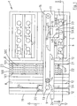
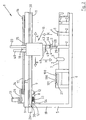
- apparatus for facilitating withdrawing liquid samples from a plurality of containers, in this embodiment of the invention a plurality of vials 2 which are located in the apparatus 1, and for transferring the liquid samples to respective vessels, cuvettes, wells or the like, in this case wells 100 of well plates 101 for analysing the liquid samples therein.
- the well plates 101 are conveyed through the apparatus 1 as will be described below to suitable analytical apparatus, where the samples in the well plates 101 are analysed.
- suitable analytical apparatus and well plates will be well known to those skilled in the art and further description thereof will not be provided.
- the vials 2 are of the type which typically are of glass terminating in an upper open mouth 3 which is closed by a closure element, typically provided by a closure cap 4 of a rubber or rubber type plastics material.
- the closure caps are penetrable by a pointed cannula, so that the pointed cannula can be urged through the closure cap 4 into the vial 2 for withdrawing a liquid sample therefrom.
- such vials would contain small quantities of the liquid to be sampled, which typically, would be a bodily fluid, such as blood, blood plasma, urine and the like.
- the closure cap 4 typically forms a relatively tight friction type sealing fit around the cannula which tends to grip the cannula, thereby making it difficult to withdraw the cannula from the closure cap 4 without holding the closure cap 4 against the pull of the cannula as the cannula is being withdrawn therefrom.
- the apparatus 1 is described for facilitating the withdrawal of liquid samples from a plurality of vials 2, the apparatus according to the invention can likewise be used for discharging liquid samples into the vials 2.
- the apparatus 1 comprises a housing 5 having a base 6 on which a plurality of transversely spaced apart parallel elongated longitudinally extending racks 7 are located for holding the vials 2 in an upright orientation spaced apart from each other.
- a guide way 21 supported on the base 6 extends transversely through the apparatus 1 along which the well plates 101 are guided through the apparatus 1 from an input end 22 to an output end 23.
- a conveying means comprising a suitable conveyor (not shown) conveys the guide plates 101 along the guide way 21 from the input end 22 to the output end 23, through which the well plates 101, the wells 100 of which contain samples to be analysed are transferred into the analytical apparatus.
- a transverse member 8 supported on a side wall 19 which extends upwardly from the base 6 extends transversely of the racks 7 and supports a gantry 9 which extends parallel to the racks 7.
- a device also according to the invention and indicated generally by the reference numeral 10 for sequentially withdrawing the liquid samples from the respective vials 2 through the closure caps 4 of the respective vials 2 and for transferring the liquid samples into the wells 100 of the well plates 101 is mounted on the gantry 9.
- the device 10 is described in detail below.
- the gantry 9 comprises a first guide means provided by an elongated carrier member 11 extending longitudinally relative to the racks 7 along which the device 10 is longitudinally slideable in the direction of the arrows A and B for guiding the device 10 into selective alignment with the vials 2 in the respective racks 7.
- a second guide means comprising a pair of spaced apart parallel transversely extending guide tracks 12 which are mounted on the transverse member 8 slideably engages the gantry 9 for guiding the gantry 9 in the direction of the arrows C and D transversely across the racks 7 for selective alignment of the device 10 with the respective racks 7.
- a first drive means namely, a first drive motor 13 located in the gantry 9 is provided for driving the device 10 along the carrier member 11 for selective alignment with the vials 2 in the respective racks 7.
- the drive motor 13 drives a toothed drive pulley 14, which in turn drives a toothed endless belt 15 extending around the drive pulley 14 and a toothed idler pulley 16 at the opposite end of the gantry 9 to that of the drive pulley 14.
- Drive is transmitted to the drive pulley 14 by the drive motor 13 through a belt drive 24.
- the device 10 is secured to one leg 17 of the belt 15 at 18 so that as the first drive motor 13 drives the leg 17 of the belt 15 in the direction of the arrows A and B, the device 10 is selectively alignable with the vials 2 in the rack 7.
- the first drive motor 13 is a stepper motor for facilitating incremental drive of the device 10 along the carrier member 11 in incremental steps for accurate alignment of the device 10 with the vials 2 in the racks 7 with which the device 10 is aligned.
- a second drive means comprising a second drive motor 20 also located in the gantry 9 drives the gantry 9 transversely in the direction of the arrows C and D along the guide tracks 12 for selective alignment of the device 10 with the racks 7.
- the second drive motor 20 drives a pinion 53 which is engageable with a gear rack 54 extending along the transverse member 8 between the guide tracks 12 for driving the gantry 9 in the direction of the arrows C and D.
- the second drive motor is a stepper motor for facilitating incremental movement of the gantry 9 in the direction of the arrows C and D for accurately aligning the device 10 with the racks 7.
- the device 10 for withdrawing liquid samples from the vials 2 and transferring the liquid samples to the wells 100 of the well plate 101 will now be described.
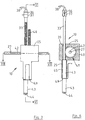
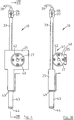
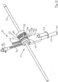
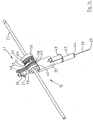
- the device 10 comprises a housing 25 which is slideably engageable with the carrier member 11 and is slideable longitudinally along the carrier member 11 in the direction of the arrows A and B.
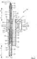
- a third drive means namely, a third drive motor 26 located on the gantry 9 drives an elongated drive shaft 27 which extends along the carrier member 11, and which in turn drives a cannula 28 vertically upwardly and downwardly in the housing 25 for penetrating the closure caps 4 of the respective vials 2 and for urging the cannula 28 into the vials 2 for withdrawing the liquid samples therefrom.
- the drive shaft 27 is rotatably carried in bearings 30 at respective opposite ends thereof which are mounted in the gantry 9. Bearings (not shown) located in the housing 25 accommodate rotation of the drive shaft 27 in the housing 25, and the bearings (not shown) in the housing 25 also accommodate sliding of the housing 25 and in turn the device 10 along the drive shaft 27.
- the cannula 28 is housed within a vertically extending hollow tubular first gear rack 33 of circular transverse cross-section having an elongated bore 34 extending therethrough within which the cannula 28 is accommodated.
- the cannula 28 is secured to the first gear rack 33 at a top end 35 thereof by a gland nut 36 which engages a mounting member 37 mounted on the top end 35 of the first gear rack 33.
- the cannula 28 extends through the mounting member 37 and the gland nut 36 and is sealably secured to a tube 38 to which a vacuum is selectively applied for withdrawing liquid samples from the vials 2 into the cannula 28 for pipetting the liquid samples from the vials 2 to the wells 100 of the well plates 101.
- the cannula 28 extends downwardly through the bore 34 of the first gear rack 33 and exits the bore 34 at a bottom end 32 of the first gear rack 33.
- the first gear rack 33 is slideable vertically in a first guide bore 39 extending through the housing 25.
- a drive transmission means namely, a drive transmission 41 comprising a first drive element, namely, a first gearwheel 40 which is keyed to the drive shaft 27 transmits drive from the drive shaft 27 to the first gear rack 33 for urging the first gear rack 33 vertically downwardly and upwardly in the direction of the arrows H and K, respectively, through the first guide bore 39, for in turn urging the cannula 28 downwardly and upwardly in the direction of the arrows H and K for urging the cannula 28 into the vials 2 through the closure caps 4.
- a keyway 42 extending longitudinally along the drive shaft 27 slideably engages a key (not shown) which keys the first gearwheel 40 to the drive shaft 27.
- An abutment means comprising a tubular abutment member 43 having an abutment end cap 44 engages the closure caps 4 of the vials 2 while the cannula 28 is being withdrawn through the closure caps 4 for preventing displacement of the closure caps 4 from the vials 2.
- the abutment member 43 is vertically slideable in a second guide bore 45 in the housing 25, which extends from and is coaxial with the first guide bore 39 in the housing 25.
- a bore 46 extending through the abutment member 43 slideably accommodates the first gear rack 33 within the abutment member 43 for facilitating relative movement between the first gear rack 33 and the abutment member 43, for in turn permitting relative movement between the cannula 28 and the abutment member 43, so that when the abutment member 43 is in engagement with one of the closure caps 4, the cannula 28 can move downwardly relative to the abutment member 43, for extending into the corresponding vial 2 through the closure cap 4.
- a cannula accommodating bore 47 in the abutment end cap 44 accommodates the cannula 28 through the abutment end cap 44 for facilitating relative movement of the cannula 28 relative to the abutment member 43.
- a second gear rack 48 is coupled to the abutment member 43 through a coupling bracket 49, and the second gear rack 48 is vertically slideable upwardly and downwardly through a third guide bore 50 in the housing 25.
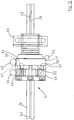
- the drive transmission 41 also comprises a second drive transmission element, namely, a second gearwheel 51 which is rotatably carried on the drive shaft 27 and is driven by the drive shaft 27 through the first gearwheel 40 and through a clutch means, namely, a dog clutch 52.
- the dog clutch 52 is adapted to decouple drive from the first gearwheel 40 to the second gearwheel 51 when the abutment member 43 engages the closure cap 4 of the vial 2 with which the device 10 is aligned, so that further driving of the first gearwheel 40 by the drive shaft 27 drives only the first gear rack 33 downwardly for in turn driving the cannula 28 into the vial 2 through the closure cap 4.
- a retaining means, in this embodiment of the invention provided by a third gear rack 55 is fixedly mounted in a bore 56 in the housing 25, and is engageable by the second gearwheel 51 while the second gearwheel 51 is decoupled from the first gearwheel 40 by the clutch 52 for preventing rotation of the second gearwheel 51. Additionally, the second gearwheel 51 is simultaneously engageable with the third gear rack 55 and the second gear rack 48 so that while the second gearwheel 51 is decoupled from the first gearwheel 40 by the dog clutch 52, the second gear rack 48 is retained fixed with the abutment member 43 engaging the closure cap 4 of the corresponding vial 2.
- the abutment member 43 is retained in engagement with the closure cap 4 by the action of the third gear rack 55 on the second gearwheel 51 until the second gearwheel 51 is again recoupled with the first gearwheel 40 by the clutch 52.
- the cannula 28 has been withdrawn from the vial 2 and the closure cap 4 into the bore 46 of the abutment member 43, thereby permitting withdrawal of the cannula 28 from the vial 2 through the closure cap 4 without displacement of the closure cap 4.
- the dog clutch 52 is essentially formed by the first and second gearwheels 40 and 51 adjacent their respective abutting radial faces 57 and 58, respectively.
- An engagement means in this embodiment of the invention a ball 60 which is housed in the first gearwheel 40 extends longitudinally outwardly of the radial face 57 of the first gearwheel 40 and is engageable with a corresponding substantially hemispherical recess 61 formed in the radial face 58 of the second gearwheel 51 for transferring drive from the first gearwheel 40 to the second gearwheel 51.
- An urging means comprising a compression spring 62, see Figs. 7 to 9 and 11 , acting between the second gearwheel 51 and a thrust bearing 63 rotatable in the housing 25 and also rotatable on the drive shaft 27 urges the second gearwheel 51 into engagement with the first gearwheel 40 so that the radial faces 57 and 58 of the first and second gearwheels 40 and 41, respectively, abut each other with the ball 60 engaged in the recess 61 for transmitting drive from the first gearwheel 40 to the second gearwheel 51.
- a bearing means namely, an arcuate bearing surface 65 extends circumferentially from the recess 61 around the radial face 58 of the second gearwheel 51 for slideably engaging the ball 60 while the second gearwheel 51 is decoupled from the first gearwheel 40.
- the ratio of the linear movement of the first gear rack 33 for each incremental angular displacement of the first gearwheel 40 is such that the maximum distance of relative travel of the first gear rack 33 and in turn the cannula 28 relative to the abutment member 43 corresponds to less than a full 360° revolution of the first gearwheel 40. This thus avoids any danger of the ball 60 re-engaging the recess 61 during further downward movement of the first gear rack 33 and in turn the cannula 28 relative to the abutment member 43.
- the drive transmission 41 which transmits drive from the third drive motor 26 through the drive shaft 27 to the cannula 28 and the abutment member 43 is responsive to the abutment member 43 engaging the closure cap 4 of the vial 2 with which the device 10 is aligned for urging the cannula 28 relative to the abutment member 43 into the vial 2, and furthermore, the drive transmission 41 is responsive to the cannula 28 being withdrawn from the vial 2 and the closure cap 4 for permitting simultaneous movement of the cannula 28 and the abutment member 43 away from the vial 2.
- the first and second gear racks 33 and 48 are set relative to the first and second gearwheels 40 and 51 so that when the ball 60 is engaged in the recess 61 with the dog clutch 52 coupling the first and second gearwheels 40 and 51, the first gear rack 33 is located relative to the second gear rack 48 so that the cannula 28 is located fully within the bore 46 of the abutment member 43 as illustrated in Fig. 7 .
- the cannula 28 and the abutment member 43 move simultaneously with each other with the cannula 28 located fully within the bore 46 of the abutment member 43.
- the apparatus 1 In use, with vials 2 loaded into the racks 7 of the apparatus 1 and the tube 38 coupled to a suitably controlled vacuum system, the apparatus 1 is ready for use. With the cannula 28 located within the abutment member 43, and the abutment member 43 raised above the level of the vials 2, in order to withdraw a liquid sample from a selected one of the vials 2, the second drive motor 20 is operated for urging the gantry 9 along the guide tracks 12 to align the device 10 with the rack 7 within which the selected vial 2 is located. The first drive motor 13 is then operated for urging the device 10 along the carrier member 11 to align the device 10 with the selected vial 2 in the selected rack 7. It will be appreciated that the first and second drive motors 13 and 20 could be simultaneously operated for aligning the device 10 with the selected vial 2.
- the third drive motor 26 is operated for driving the drive shaft 27 for in turn driving the first gearwheel 40 and in turn the second gearwheel 51 for simultaneously driving the first and second gear racks 33 and 48 downwardly for in turn simultaneously driving the cannula 28 and the abutment member 43 downwardly until the abutment member 43 engages the closure cap 4 of the selected vial 2.
- the resistance encountered by the abutment member 43 on engaging the closure cap 4 of the selected vial 2 causes the dog clutch 52 to decouple the second gearwheel 51 from the first gearwheel 40.
- the ball 60 disengages the recess 61 and engages the bearing surface 65
- the second gearwheel 51 is urged into engagement with the third gear rack 55, while still in engagement with the second gear rack 48. This, thus, prevents further downward movement of the abutment member 43 and retains the abutment member 43 in engagement with the closure cap 4.
- the vacuum is isolated from the tube 38.
- the drive shaft 27 is operated in reverse for urging the first gear rack 33, and in turn the cannula 28 upwardly until the cannula 28 has disengaged the closure cap 4 and is located within the bore 46 of the abutment member 43.
- the dog clutch 52 recouples the second gearwheel 51 to the first gearwheel 40, and the second gearwheel 51 disengages the third gear rack 55.
- the first and second drive motors 13 and 20 are simultaneously or sequentially operated for aligning the device 10 with a selected one of the wells 100 of the well plates 101 to which the liquid sample is to be transferred.
- the drive motor 26 is operated for driving the cannula 28 and the abutment member 43 downwardly towards the selected well 100, and the liquid sample is discharged from the cannula 28 into the well 100.
- the apparatus 1 is ready to withdraw a liquid sample from the next to be selected of the vials 2, and operation of the apparatus 1 for withdrawing the next liquid sample is similar to that already described.
- a particularly important advantage of the invention is that the device 10, and the apparatus 1 can be used for taking samples from vials of different height, where the closure caps 4 thereof are at different distances from the device 10. This is achieved by virtue of the fact that the first and second gear racks 33 and 48 are simultaneously urged downwardly by the first and second gearwheels 40 and 51 until the abutment member 43 engages the closure cap 4 of the vial 2 with which the device 10 is aligned. Only at that stage when the abutment member 43 is in engagement with the closure cap 4 is the cannula 28 urged outwardly of the abutment member 43 to penetrate the closure cap 4 into the vial 2.
- the cannula 28 remains within the abutment member 43 until the closure cap 4 is engaged by the abutment member 43, and only then is the cannula 28 urged outwardly through the closure cap 4 into the vial 2.
- a further and also particularly important advantage of the invention is the fact that the retaining means, which in this embodiment of the invention is described as being the third gear rack 55, is provided for retaining the abutment member 43 in engagement with the closure cap until the cannula 28 has been withdrawn from the closure cap.
- the second gearwheel 51 will always be engaged with the third gear rack 55 during relative movement of the cannula 28 relative to the abutment member 43, and thus the abutment member 43 will be retained in engagement with the closure cap 4 until the cannula 28 has been withdrawn into the abutment member 43.
- the apparatus may be used for withdrawing liquid samples from any type of container, and indeed, it will be appreciated by those skilled in the art that the apparatus and device may be scaled up or scaled down, depending on the general sizes of the containers with which the apparatus and device is to be used. It will also be appreciated that the apparatus and the device according to the invention may be used for discharging by way of pipetting a liquid sample into a vial or other such container, or from one vial to another.
- the apparatus and the device according to the invention may be used for withdrawing liquid samples from containers which may not have a closure element closing an open mouth of the container.
- the abutment member would act as a probe to engage the container adjacent the open mouth, and once the container had been engaged by the abutment member adjacent the open mouth, the cannula could then be extended from the abutment member into the container for withdrawing the liquid sample. This would thus prevent the cannula being urged outwardly of the abutment member until the container had been engaged by the abutment member.
- the abutment means instead of abutting the closure cap of the selected vial, may instead abut or engage the vial, and if the abutment means abuts or engages the vial, it is envisaged that the abutment means would, although not necessarily, engage the vial adjacent the open mouth.
Landscapes
- Life Sciences & Earth Sciences (AREA)
- Health & Medical Sciences (AREA)
- Chemical & Material Sciences (AREA)
- Zoology (AREA)
- Organic Chemistry (AREA)
- Engineering & Computer Science (AREA)
- Bioinformatics & Cheminformatics (AREA)
- General Health & Medical Sciences (AREA)
- Biochemistry (AREA)
- Wood Science & Technology (AREA)
- Biotechnology (AREA)
- Physics & Mathematics (AREA)
- Microbiology (AREA)
- General Engineering & Computer Science (AREA)
- Biomedical Technology (AREA)
- Genetics & Genomics (AREA)
- Molecular Biology (AREA)
- Sustainable Development (AREA)
- Analytical Chemistry (AREA)
- General Physics & Mathematics (AREA)
- Immunology (AREA)
- Pathology (AREA)
- Automatic Analysis And Handling Materials Therefor (AREA)
- Sampling And Sample Adjustment (AREA)
Claims (15)
- Vorrichtung zur Entnahme von Flüssigkeitsproben aus jeweiligen Behältern einer Mehrzahl Behälter (2) oder zum Einfüllen von Flüssigkeitsproben in jeweilige Behälter einer Mehrzahl Behälter (2), wobei die Vorrichtung ein Gestell (7) zur Aufnahme der Behälter (2) aufweist und eine Einrichtung (10) zur Entnahme einer Flüssigkeitsprobe aus einem ausgewählten Behälter (2) oder zum Einfüllen einer Flüssigkeitsprobe in einen ausgewählten Behälter (2) aufweist, wobei die Einrichtung (10) an der Vorrichtung über dem Gestell (7) angebaut und relativ zum Gestell (7) zur selektiven Ausrichtung auf den jeweiligen der Behälter (2) beweglich ist, wobei die Einrichtung (10) eine Kanüle (28), die sich in einen ausgewählten der Behälter (2) erstrecken kann, ein Anschlagmittel (43) zum Eingriff in einen ausgewählten Behälter (2) und ein Verschlusselement (4), das eine offene Mündung (3) des ausgewählten Behälters (2) verschließt, und ein Kraftübertragungsmittel mit einem ersten Kraftübertragungselement (40) zum Drücken der Kanüle (28) in den ausgewählten Behälter (2), und zum Herausziehen der Kanüle (28) aus dem ausgewählten Behälter (2) aufweist,
dadurch gekennzeichnet, dass das Kraftübertragungsmittel ein zweites Kraftübertragungselement (51) aufweist, um das Anschlagmittel mit dem einen der ausgewählten Behälter (2) und dem Verschlusselement (4) des ausgewählten Behälters (2) in und außer Eingriff zu bringen, wobei das zweite Kraftübertragungselement (51) vom ersten Kraftübertragungselement (40) über ein Kupplungsmittel (52) angetrieben wird, wobei das Kupplungsmittel (52) das erste und dass zweite Kraftübertragungselement (40, 51) sowie ein Eingriffsmittel (60) aufweist, das sich von entweder dem ersten oder dem zweiten Kraftübertragungselement (40, 51) aus erstreckt, um mit einem entsprechenden Aufnahmemittel (61) am anderen des ersten oder des zweiten Kraftübertragungselements (40, 51) zur selektiven Kraftübertragung vom ersten Kraftübertragungselement (40) zum zweiten Kraftübertragungselement (51) in lösbaren Eingriff zu kommen, wobei die Einrichtung (10) an der Vorrichtung (1) so angebaut ist, dass die Kanüle (28) und das Anschlagmittel (43) von dem ersten und dem zweiten Kraftübertragungselement (40, 51) gleichzeitig zu einem ausgewählten Behälter (2) gedrückt werden können, und das Kupplungsmittel (52) auf den Eingriff des Anschlagmittels (43) mit einem der ausgewählten Behälter (2) und dem Verschlusselement (4) anspricht, um das zweite Kraftübertragungselement (51) vom ersten Kraftübertragungselement (40) zu entkoppeln, so dass die Kanüle (28) durch das erste Kraftübertragungselement (40) relativ zum Anschlagmittel (43) in den ausgewählten Behälter (2) mit dem Verschlusselement (4) in Eingriff mit dem einen ausgewählten Behälter (2) und dem Verschlusselement (4) gedrückt wird. - Vorrichtung nach Anspruch 1, durch gekennzeichnet, dass ein Sicherungsmittel (55) dazu eingerichtet ist, das Anschlagmittel (43) in Eingriff mit dem einen ausgewählten Behälter (2) und dem Verschlusselement (4) während der Bewegung der Kanüle (28) relativ zum Anschlagelement (43) in einer Richtung aus dem Behälter (2) heraus zu halten.
- Vorrichtung nach Anspruch 2, durch gekennzeichnet, dass das Sicherungsmittel (55) dazu eingerichtet ist, das Anschlagmittel (43) in Eingriff mit dem einen ausgewählten Behälter (2) und dem Verschlusselement (4) während der Bewegung der Kanüle (28) relativ zum Anschlagelement (43) in einer Richtung in den Behälter (2) hinein zu halten.
- Vorrichtung nach Anspruch 2 oder 3, durch gekennzeichnet, dass das zweite Kraftübertragungselement (51) mit dem Sicherungsmittel (55) zusammenwirken kann, wenn das zweite Kraftübertragungselement (51) vom ersten Kraftübertragungselement (40) entkoppelt ist, um das Anschlagmittel (43) in Eingriff mit dem gewählten Behälter (2) und dem Verschlusselement (4) zu halten.
- Vorrichtung nach einem der vorigen Ansprüche, dadurch gekennzeichnet, dass das Kupplungsmittel (52) auf die Strecke anspricht, um die die Kanüle (28) relativ zum Anschlagmittel (43) in einer Richtung aus dem Behälter (2) hinaus bewegt wird, der im Wesentlichen ungefähr gleich ist der Strecke, um die die Kanüle (28) zuvor nach dem Eingriff des Anschlagmittels (43) mit dem ausgewählten Behälter (2) und dem Verschlusselement (4) zum erneuten Koppeln des zweiten Kraftübertragungselements (51) mit dem ersten Kraftübertragungselement (40) relativ zum Anschlagmittel (43) in einer Richtung in den Behälter (2) hinein bewegt worden ist.
- Vorrichtung nach einem der vorigen Ansprüche, dadurch gekennzeichnet, dass ein Lagermittel (65) entweder am ersten oder am zweiten Kraftübertragungselement (40, 51) vorgesehen ist, in dem sich das Aufnahmemittel (61) befindet, um die relative Bewegung zwischen dem Eingriffsmittel (60) und dem Lagermittel (65) aufzunehmen, um wiederum die relative Bewegung zwischen dem ersten und dem zweiten Kraftübertragungselement (40, 51) aufzunehmen.
- Vorrichtung nach Anspruch 6, durch gekennzeichnet, dass das Lagermittel (65) eine Lageroberfläche (65) aufweist, die sich vom Aufnahmemittel (61) aus erstreckt, wobei die Lageroberfläche (65) eine Länge hat, die sich vom Aufnahmemittel (61) hinreichend weit erstreckt, um die maximale Strecke der relativen Bewegung der Kanüle (28) relativ zum Anschlagmittel (43) in einer Richtung in den Behälter (2) hinein aufzunehmen.
- Vorrichtung nach einem der vorigen Ansprüche, dadurch gekennzeichnet, dass ein Druckmittel (62) bereitgestellt ist, um das Eingriffsmittel (60) in Eingriff mit dem Aufnahmemittel (61) des Kupplungsmittels (52) zu drücken.
- Vorrichtung nach einem der vorigen Ansprüche, dadurch gekennzeichnet, dass sich das Eingriffsmittel (60) und das Aufnahmemittel (61) auf jeweiligen radialen Flächen (57, 58) des ersten und des zweiten Kraftübertragungselements (40, 51) befinden.
- Vorrichtung nach einem der vorigen Ansprüche, dadurch gekennzeichnet, dass das erste Kraftübertragungselement (40) ein erstes Zahnrad (40) aufweist, das mit einer ersten Zahnstange (33), an der die Kanüle (28) befestigt ist, in Eingriff gebracht werden kann.
- Vorrichtung nach Anspruch 10, durch gekennzeichnet, dass das erste Zahnrad (40) so konfiguriert ist, dass das Verhältnis der von der ersten Zahnstange (33) zurückgelegten linearen Strecke zu jeder Winkelverschiebung des ersten Zahnrads (40) derart ist, dass die zum Antrieb der ersten Zahnstange (33) um eine Strecke entsprechend der maximalen Strecke der relativen Bewegung zwischen der Kanüle (2() und dem Anschlagmittel (43) in einer Richtung in den Behälter (2) hinein erforderliche Winkelverschiebung des ersten Zahnrads (40) kleiner ist als 360°.
- Vorrichtung nach einem der vorigen Ansprüche, dadurch gekennzeichnet, dass das zweite Kraftübertragungselement (51) ein zweites Zahnrad (51) aufweist, das mit einer zweiten Zahnstange (48), an der das Anschlagmittel (43) befestigt ist, in Eingriff gebracht werden kann.
- Vorrichtung nach Anspruch 10, durch gekennzeichnet, dass das Sicherungsmittel (55) eine dritte Zahnstange (55) aufweist, mit der das zweite Zahnrad (51) in Eingriff gebracht werden kann, wobei die dritte Zahnstange (55) relativ zum zweiten Zahnrad (51) fixiert ist, um eine Rotation desselben zu verhindern, wenn das zweite Zahnrad (51) mit der Zahnstange in Eingriff steht.
- Vorrichtung nach einem der vorigen Ansprüche, dadurch gekennzeichnet, dass das erste Kraftübertragungselement (40) mit einer Antriebswelle (27) formschlüssig verbunden ist, um von dieser mit Kraft beaufschlagt zu werden, und das zweite Kraftübertragungselement (51) auf der Antriebswelle (27) installiert ist.
- Vorrichtung nach einem der vorigen Ansprüche, dadurch gekennzeichnet, dass die Kanüle (28) zum Durchdringen der Verschlusselemente (4) der Behälter (2) ausgeführt ist, so dass sie sich durch das Verschlusselement (4) in den ausgewählten der Behälter (2) erstreckt.
Applications Claiming Priority (2)
| Application Number | Priority Date | Filing Date | Title |
|---|---|---|---|
| IE20060824 | 2006-11-15 | ||
| PCT/IE2007/000111 WO2008059470A2 (en) | 2006-11-15 | 2007-11-15 | A device for withdrawing or for discharging a liquid sample from or into a container1 |
Publications (2)
| Publication Number | Publication Date |
|---|---|
| EP2084258A2 EP2084258A2 (de) | 2009-08-05 |
| EP2084258B1 true EP2084258B1 (de) | 2017-12-13 |
Family
ID=39154322
Family Applications (1)
| Application Number | Title | Priority Date | Filing Date |
|---|---|---|---|
| EP07827124.4A Active EP2084258B1 (de) | 2006-11-15 | 2007-11-15 | Vorrichtung zur entnahme oder einfüllen einer flüssigkeit aus oder in behälter |
Country Status (6)
| Country | Link |
|---|---|
| US (1) | US8349278B2 (de) |
| EP (1) | EP2084258B1 (de) |
| ES (1) | ES2662492T3 (de) |
| IE (1) | IES20070831A2 (de) |
| TR (1) | TR201802513T4 (de) |
| WO (1) | WO2008059470A2 (de) |
Families Citing this family (4)
| Publication number | Priority date | Publication date | Assignee | Title |
|---|---|---|---|---|
| US10414183B2 (en) * | 2016-08-29 | 2019-09-17 | Joseph L. Zeleny | Free axis or free-rolling printer |
| CN109520780B (zh) * | 2018-11-13 | 2021-03-19 | 深圳市心月生物科技有限公司 | 一种地沟油分析仪 |
| CN113607481B (zh) * | 2021-07-30 | 2023-12-26 | 北京顺鑫石门检测技术有限责任公司 | 一种半流质食品检测取样装置 |
| LU102878B1 (en) | 2021-11-15 | 2023-05-15 | Stratec Se | Pipetting unit |
Citations (1)
| Publication number | Priority date | Publication date | Assignee | Title |
|---|---|---|---|---|
| US5935523A (en) * | 1997-05-29 | 1999-08-10 | Medical Laboratory Automation, Inc. | Apparatus for accessing a sealed container |
Family Cites Families (7)
| Publication number | Priority date | Publication date | Assignee | Title |
|---|---|---|---|---|
| AT397610B (de) | 1990-06-01 | 1994-05-25 | Avl Verbrennungskraft Messtech | Vorrichtung zur entnahme von körperflüssigkeiten |
| WO1997011347A1 (fr) | 1995-09-18 | 1997-03-27 | Acs S.A. | Dispositif et procede de prelevement et/ou de mesure de liquide |
| DE10048643A1 (de) | 1999-09-22 | 2001-05-31 | Biopsytec Gmbh | Vorrichtung zur automatisierten Probennahme und Befüllung von Mikrotiterplatten mit Pflanzenmaterial |
| WO2001084108A2 (en) * | 2000-05-01 | 2001-11-08 | Glaxo Group Limited | Automated sample collection workstation |
| DE10129246A1 (de) | 2001-06-18 | 2003-01-02 | Bartec Logistic Man Gmbh | Verfahren und Vorrichtung zur Entnahme einer Probe aus einer Fluidcharge |
| US7481978B2 (en) * | 2005-03-23 | 2009-01-27 | Beckman Coulter, Inc. | Apparatus for aspirating liquids from sealed containers |
| FR2892821B1 (fr) | 2005-11-02 | 2008-02-01 | Concept Pro Sarl | Dispositif integre et/ou automatise pour le reperage et/ou la tracabilite de recipients d'echantillonnage de prelevements primaires medicaux ou veterinaires |
-
2007
- 2007-11-15 ES ES07827124.4T patent/ES2662492T3/es active Active
- 2007-11-15 IE IE20070831A patent/IES20070831A2/en not_active IP Right Cessation
- 2007-11-15 WO PCT/IE2007/000111 patent/WO2008059470A2/en not_active Ceased
- 2007-11-15 EP EP07827124.4A patent/EP2084258B1/de active Active
- 2007-11-15 TR TR2018/02513T patent/TR201802513T4/tr unknown
- 2007-11-15 US US12/515,043 patent/US8349278B2/en active Active
Patent Citations (1)
| Publication number | Priority date | Publication date | Assignee | Title |
|---|---|---|---|---|
| US5935523A (en) * | 1997-05-29 | 1999-08-10 | Medical Laboratory Automation, Inc. | Apparatus for accessing a sealed container |
Also Published As
| Publication number | Publication date |
|---|---|
| US20100212437A1 (en) | 2010-08-26 |
| ES2662492T3 (es) | 2018-04-06 |
| US8349278B2 (en) | 2013-01-08 |
| EP2084258A2 (de) | 2009-08-05 |
| WO2008059470A2 (en) | 2008-05-22 |
| IES20070831A2 (en) | 2009-03-04 |
| TR201802513T4 (tr) | 2018-03-21 |
| WO2008059470A3 (en) | 2008-07-31 |
Similar Documents
| Publication | Publication Date | Title |
|---|---|---|
| EP1883473B1 (de) | Verfahren und vorrichtung zur flüssigkeitsaspiration aus versiegelten behältern | |
| JP6200923B2 (ja) | 微生物の自動検出装置 | |
| EP3798639B1 (de) | Greifer und verfahren zur automatisierten handhabung von probenröhrchen | |
| US8268263B2 (en) | Reagent cartridge | |
| US12474360B2 (en) | Sample tube decapper | |
| US20120186200A1 (en) | Vial capper/decapper for use with a liquid transfer system | |
| US8349278B2 (en) | Apparatus for withdrawing a liquid sample from selected ones of a plurality of containers | |
| CN110596408A (zh) | 一种全自动干式免疫分析设备 | |
| WO1998021595A1 (en) | Automatic chemistry analyzer with sample cup stopper piercing assembly | |
| US10669520B2 (en) | Automated bioreactor sampling and glucose monitoring system | |
| CN112730867A (zh) | 一种流式分析仪的样本制备装置及制备方法 | |
| EP1808700B1 (de) | Verfahren und Vorrichtung für Probeverarbeitung und -injektion | |
| US8297151B1 (en) | Apparatus for opening and closing a specimen vial | |
| CN215866722U (zh) | 一种流式分析仪的样本制备装置 | |
| JP2002519665A (ja) | 閉じた容器から液体サンプルを抽出する方法および装置 | |
| EP1852704B1 (de) | Probeneingabevorrichtung | |
| CN211505576U (zh) | 一种全自动干式免疫分析设备 | |
| EP0468565A2 (de) | Durchstechende Probenahmesonde | |
| CN222652981U (zh) | 一种尿蛋白自动分析仪 | |
| CN104007279A (zh) | 自动取样机的压脱式进料移料卸料系统 | |
| CN115181662B (zh) | 一种用于磁珠法检测的密封式一体化装置及其应用 | |
| CN120468137A (zh) | 样品油抗乳化测定系统及方法 |
Legal Events
| Date | Code | Title | Description |
|---|---|---|---|
| PUAI | Public reference made under article 153(3) epc to a published international application that has entered the european phase |
Free format text: ORIGINAL CODE: 0009012 |
|
| 17P | Request for examination filed |
Effective date: 20090518 |
|
| AK | Designated contracting states |
Kind code of ref document: A2 Designated state(s): AT BE BG CH CY CZ DE DK EE ES FI FR GB GR HU IE IS IT LI LT LU LV MC MT NL PL PT RO SE SI SK TR |
|
| DAX | Request for extension of the european patent (deleted) | ||
| RAP1 | Party data changed (applicant data changed or rights of an application transferred) |
Owner name: TRINITY BIOTECH MANUFACTURING LIMITED |
|
| RAP1 | Party data changed (applicant data changed or rights of an application transferred) |
Owner name: TCOAG IRELAND LIMITED |
|
| STAA | Information on the status of an ep patent application or granted ep patent |
Free format text: STATUS: EXAMINATION IS IN PROGRESS |
|
| 17Q | First examination report despatched |
Effective date: 20161219 |
|
| GRAP | Despatch of communication of intention to grant a patent |
Free format text: ORIGINAL CODE: EPIDOSNIGR1 |
|
| STAA | Information on the status of an ep patent application or granted ep patent |
Free format text: STATUS: GRANT OF PATENT IS INTENDED |
|
| INTG | Intention to grant announced |
Effective date: 20170823 |
|
| GRAS | Grant fee paid |
Free format text: ORIGINAL CODE: EPIDOSNIGR3 |
|
| GRAA | (expected) grant |
Free format text: ORIGINAL CODE: 0009210 |
|
| STAA | Information on the status of an ep patent application or granted ep patent |
Free format text: STATUS: THE PATENT HAS BEEN GRANTED |
|
| AK | Designated contracting states |
Kind code of ref document: B1 Designated state(s): AT BE BG CH CY CZ DE DK EE ES FI FR GB GR HU IE IS IT LI LT LU LV MC MT NL PL PT RO SE SI SK TR |
|
| REG | Reference to a national code |
Ref country code: GB Ref legal event code: FG4D |
|
| REG | Reference to a national code |
Ref country code: AT Ref legal event code: REF Ref document number: 954372 Country of ref document: AT Kind code of ref document: T Effective date: 20171215 Ref country code: CH Ref legal event code: EP |
|
| REG | Reference to a national code |
Ref country code: IE Ref legal event code: FG4D |
|
| REG | Reference to a national code |
Ref country code: DE Ref legal event code: R096 Ref document number: 602007053408 Country of ref document: DE |
|
| REG | Reference to a national code |
Ref country code: NL Ref legal event code: FP |
|
| REG | Reference to a national code |
Ref country code: SE Ref legal event code: TRGR |
|
| REG | Reference to a national code |
Ref country code: CH Ref legal event code: NV Representative=s name: CRONIN INTELLECTUAL PROPERTY, CH |
|
| REG | Reference to a national code |
Ref country code: ES Ref legal event code: FG2A Ref document number: 2662492 Country of ref document: ES Kind code of ref document: T3 Effective date: 20180406 |
|
| REG | Reference to a national code |
Ref country code: LT Ref legal event code: MG4D |
|
| PG25 | Lapsed in a contracting state [announced via postgrant information from national office to epo] |
Ref country code: LT Free format text: LAPSE BECAUSE OF FAILURE TO SUBMIT A TRANSLATION OF THE DESCRIPTION OR TO PAY THE FEE WITHIN THE PRESCRIBED TIME-LIMIT Effective date: 20171213 Ref country code: FI Free format text: LAPSE BECAUSE OF FAILURE TO SUBMIT A TRANSLATION OF THE DESCRIPTION OR TO PAY THE FEE WITHIN THE PRESCRIBED TIME-LIMIT Effective date: 20171213 |
|
| REG | Reference to a national code |
Ref country code: AT Ref legal event code: MK05 Ref document number: 954372 Country of ref document: AT Kind code of ref document: T Effective date: 20171213 Ref country code: CH Ref legal event code: PCAR Free format text: NEW ADDRESS: CHEMIN DE LA VUARPILLIERE 29, 1260 NYON (CH) |
|
| PG25 | Lapsed in a contracting state [announced via postgrant information from national office to epo] |
Ref country code: GR Free format text: LAPSE BECAUSE OF FAILURE TO SUBMIT A TRANSLATION OF THE DESCRIPTION OR TO PAY THE FEE WITHIN THE PRESCRIBED TIME-LIMIT Effective date: 20180314 Ref country code: LV Free format text: LAPSE BECAUSE OF FAILURE TO SUBMIT A TRANSLATION OF THE DESCRIPTION OR TO PAY THE FEE WITHIN THE PRESCRIBED TIME-LIMIT Effective date: 20171213 Ref country code: BG Free format text: LAPSE BECAUSE OF FAILURE TO SUBMIT A TRANSLATION OF THE DESCRIPTION OR TO PAY THE FEE WITHIN THE PRESCRIBED TIME-LIMIT Effective date: 20180313 |
|
| PG25 | Lapsed in a contracting state [announced via postgrant information from national office to epo] |
Ref country code: CZ Free format text: LAPSE BECAUSE OF FAILURE TO SUBMIT A TRANSLATION OF THE DESCRIPTION OR TO PAY THE FEE WITHIN THE PRESCRIBED TIME-LIMIT Effective date: 20171213 Ref country code: CY Free format text: LAPSE BECAUSE OF FAILURE TO SUBMIT A TRANSLATION OF THE DESCRIPTION OR TO PAY THE FEE WITHIN THE PRESCRIBED TIME-LIMIT Effective date: 20171213 Ref country code: EE Free format text: LAPSE BECAUSE OF FAILURE TO SUBMIT A TRANSLATION OF THE DESCRIPTION OR TO PAY THE FEE WITHIN THE PRESCRIBED TIME-LIMIT Effective date: 20171213 Ref country code: SK Free format text: LAPSE BECAUSE OF FAILURE TO SUBMIT A TRANSLATION OF THE DESCRIPTION OR TO PAY THE FEE WITHIN THE PRESCRIBED TIME-LIMIT Effective date: 20171213 |
|
| PG25 | Lapsed in a contracting state [announced via postgrant information from national office to epo] |
Ref country code: RO Free format text: LAPSE BECAUSE OF FAILURE TO SUBMIT A TRANSLATION OF THE DESCRIPTION OR TO PAY THE FEE WITHIN THE PRESCRIBED TIME-LIMIT Effective date: 20171213 Ref country code: IS Free format text: LAPSE BECAUSE OF FAILURE TO SUBMIT A TRANSLATION OF THE DESCRIPTION OR TO PAY THE FEE WITHIN THE PRESCRIBED TIME-LIMIT Effective date: 20180413 Ref country code: AT Free format text: LAPSE BECAUSE OF FAILURE TO SUBMIT A TRANSLATION OF THE DESCRIPTION OR TO PAY THE FEE WITHIN THE PRESCRIBED TIME-LIMIT Effective date: 20171213 Ref country code: PL Free format text: LAPSE BECAUSE OF FAILURE TO SUBMIT A TRANSLATION OF THE DESCRIPTION OR TO PAY THE FEE WITHIN THE PRESCRIBED TIME-LIMIT Effective date: 20171213 |
|
| REG | Reference to a national code |
Ref country code: DE Ref legal event code: R097 Ref document number: 602007053408 Country of ref document: DE |
|
| PLBE | No opposition filed within time limit |
Free format text: ORIGINAL CODE: 0009261 |
|
| STAA | Information on the status of an ep patent application or granted ep patent |
Free format text: STATUS: NO OPPOSITION FILED WITHIN TIME LIMIT |
|
| 26N | No opposition filed |
Effective date: 20180914 |
|
| PG25 | Lapsed in a contracting state [announced via postgrant information from national office to epo] |
Ref country code: DK Free format text: LAPSE BECAUSE OF FAILURE TO SUBMIT A TRANSLATION OF THE DESCRIPTION OR TO PAY THE FEE WITHIN THE PRESCRIBED TIME-LIMIT Effective date: 20171213 |
|
| PG25 | Lapsed in a contracting state [announced via postgrant information from national office to epo] |
Ref country code: SI Free format text: LAPSE BECAUSE OF FAILURE TO SUBMIT A TRANSLATION OF THE DESCRIPTION OR TO PAY THE FEE WITHIN THE PRESCRIBED TIME-LIMIT Effective date: 20171213 |
|
| REG | Reference to a national code |
Ref country code: CH Ref legal event code: PL |
|
| PG25 | Lapsed in a contracting state [announced via postgrant information from national office to epo] |
Ref country code: LU Free format text: LAPSE BECAUSE OF NON-PAYMENT OF DUE FEES Effective date: 20181115 Ref country code: MC Free format text: LAPSE BECAUSE OF FAILURE TO SUBMIT A TRANSLATION OF THE DESCRIPTION OR TO PAY THE FEE WITHIN THE PRESCRIBED TIME-LIMIT Effective date: 20171213 |
|
| REG | Reference to a national code |
Ref country code: IE Ref legal event code: MM4A |
|
| PG25 | Lapsed in a contracting state [announced via postgrant information from national office to epo] |
Ref country code: CH Free format text: LAPSE BECAUSE OF NON-PAYMENT OF DUE FEES Effective date: 20181130 Ref country code: LI Free format text: LAPSE BECAUSE OF NON-PAYMENT OF DUE FEES Effective date: 20181130 |
|
| REG | Reference to a national code |
Ref country code: CH Ref legal event code: AECN Free format text: DAS PATENT WURDE AUFGRUND DES WEITERBEHANDLUNGSANTRAGS VOM 22.08.2019 REAKTIVIERT. |
|
| PG25 | Lapsed in a contracting state [announced via postgrant information from national office to epo] |
Ref country code: IE Free format text: LAPSE BECAUSE OF NON-PAYMENT OF DUE FEES Effective date: 20181115 |
|
| PG25 | Lapsed in a contracting state [announced via postgrant information from national office to epo] |
Ref country code: LI Free format text: LAPSE BECAUSE OF NON-PAYMENT OF DUE FEES Effective date: 20181130 Ref country code: CH Free format text: LAPSE BECAUSE OF NON-PAYMENT OF DUE FEES Effective date: 20181130 |
|
| PGRI | Patent reinstated in contracting state [announced from national office to epo] |
Ref country code: LI Effective date: 20190826 Ref country code: CH Effective date: 20190826 |
|
| PG25 | Lapsed in a contracting state [announced via postgrant information from national office to epo] |
Ref country code: MT Free format text: LAPSE BECAUSE OF NON-PAYMENT OF DUE FEES Effective date: 20181115 |
|
| PG25 | Lapsed in a contracting state [announced via postgrant information from national office to epo] |
Ref country code: PT Free format text: LAPSE BECAUSE OF FAILURE TO SUBMIT A TRANSLATION OF THE DESCRIPTION OR TO PAY THE FEE WITHIN THE PRESCRIBED TIME-LIMIT Effective date: 20171213 |
|
| PG25 | Lapsed in a contracting state [announced via postgrant information from national office to epo] |
Ref country code: HU Free format text: LAPSE BECAUSE OF FAILURE TO SUBMIT A TRANSLATION OF THE DESCRIPTION OR TO PAY THE FEE WITHIN THE PRESCRIBED TIME-LIMIT; INVALID AB INITIO Effective date: 20071115 |
|
| P01 | Opt-out of the competence of the unified patent court (upc) registered |
Effective date: 20230517 |
|
| PGFP | Annual fee paid to national office [announced via postgrant information from national office to epo] |
Ref country code: TR Payment date: 20250826 Year of fee payment: 19 Ref country code: IT Payment date: 20250908 Year of fee payment: 19 |
|
| PGFP | Annual fee paid to national office [announced via postgrant information from national office to epo] |
Ref country code: GB Payment date: 20250926 Year of fee payment: 19 |
|
| PGFP | Annual fee paid to national office [announced via postgrant information from national office to epo] |
Ref country code: FR Payment date: 20250828 Year of fee payment: 19 |
|
| REG | Reference to a national code |
Ref country code: CH Ref legal event code: U11 Free format text: ST27 STATUS EVENT CODE: U-0-0-U10-U11 (AS PROVIDED BY THE NATIONAL OFFICE) Effective date: 20251201 |
|
| PGFP | Annual fee paid to national office [announced via postgrant information from national office to epo] |
Ref country code: NL Payment date: 20251124 Year of fee payment: 19 |
|
| PGFP | Annual fee paid to national office [announced via postgrant information from national office to epo] |
Ref country code: DE Payment date: 20251118 Year of fee payment: 19 |
|
| PGFP | Annual fee paid to national office [announced via postgrant information from national office to epo] |
Ref country code: BE Payment date: 20251119 Year of fee payment: 19 |
|
| PGFP | Annual fee paid to national office [announced via postgrant information from national office to epo] |
Ref country code: SE Payment date: 20251015 Year of fee payment: 19 Ref country code: CH Payment date: 20251201 Year of fee payment: 19 |
|
| PGFP | Annual fee paid to national office [announced via postgrant information from national office to epo] |
Ref country code: ES Payment date: 20251201 Year of fee payment: 19 |