EP2084561B1 - Reflector and manufacturing method thereof - Google Patents
Reflector and manufacturing method thereof Download PDFInfo
- Publication number
- EP2084561B1 EP2084561B1 EP20070834255 EP07834255A EP2084561B1 EP 2084561 B1 EP2084561 B1 EP 2084561B1 EP 20070834255 EP20070834255 EP 20070834255 EP 07834255 A EP07834255 A EP 07834255A EP 2084561 B1 EP2084561 B1 EP 2084561B1
- Authority
- EP
- European Patent Office
- Prior art keywords
- reflector
- sheet
- predetermined direction
- amorphous
- stabilizer
- Prior art date
- Legal status (The legal status is an assumption and is not a legal conclusion. Google has not performed a legal analysis and makes no representation as to the accuracy of the status listed.)
- Not-in-force
Links
- 238000004519 manufacturing process Methods 0.000 title claims description 24
- 229920001887 crystalline plastic Polymers 0.000 claims description 43
- 239000000463 material Substances 0.000 claims description 36
- 238000000034 method Methods 0.000 claims description 34
- 238000002425 crystallisation Methods 0.000 claims description 26
- 230000008025 crystallization Effects 0.000 claims description 26
- 238000001125 extrusion Methods 0.000 claims description 26
- 239000012963 UV stabilizer Substances 0.000 claims description 18
- 239000002245 particle Substances 0.000 claims description 17
- 239000013078 crystal Substances 0.000 claims description 12
- 239000004611 light stabiliser Substances 0.000 claims description 11
- 238000001816 cooling Methods 0.000 claims description 7
- 229920000098 polyolefin Polymers 0.000 claims description 6
- 229920003023 plastic Polymers 0.000 claims description 5
- 239000004033 plastic Substances 0.000 claims description 5
- 229920000728 polyester Polymers 0.000 claims description 5
- 239000008188 pellet Substances 0.000 claims description 3
- 239000000203 mixture Substances 0.000 claims 1
- 239000004743 Polypropylene Substances 0.000 description 37
- -1 micro-bubbles Substances 0.000 description 23
- 239000010410 layer Substances 0.000 description 21
- 239000010408 film Substances 0.000 description 16
- 239000005020 polyethylene terephthalate Substances 0.000 description 16
- 229920000139 polyethylene terephthalate Polymers 0.000 description 16
- 229920001155 polypropylene Polymers 0.000 description 13
- 239000000654 additive Substances 0.000 description 12
- 230000000996 additive effect Effects 0.000 description 12
- 239000000049 pigment Substances 0.000 description 9
- 238000001878 scanning electron micrograph Methods 0.000 description 8
- 239000012964 benzotriazole Substances 0.000 description 7
- 238000005187 foaming Methods 0.000 description 7
- TZCXTZWJZNENPQ-UHFFFAOYSA-L barium sulfate Chemical compound [Ba+2].[O-]S([O-])(=O)=O TZCXTZWJZNENPQ-UHFFFAOYSA-L 0.000 description 6
- QRUDEWIWKLJBPS-UHFFFAOYSA-N benzotriazole Chemical compound C1=CC=C2N[N][N]C2=C1 QRUDEWIWKLJBPS-UHFFFAOYSA-N 0.000 description 6
- 239000000975 dye Substances 0.000 description 6
- 239000011148 porous material Substances 0.000 description 6
- 239000004698 Polyethylene Substances 0.000 description 5
- 239000012463 white pigment Substances 0.000 description 5
- 239000004973 liquid crystal related substance Substances 0.000 description 4
- 229920005989 resin Polymers 0.000 description 4
- 239000011347 resin Substances 0.000 description 4
- YGSDEFSMJLZEOE-UHFFFAOYSA-N salicylic acid Chemical compound OC(=O)C1=CC=CC=C1O YGSDEFSMJLZEOE-UHFFFAOYSA-N 0.000 description 4
- 150000001412 amines Chemical class 0.000 description 3
- RWCCWEUUXYIKHB-UHFFFAOYSA-N benzophenone Chemical compound C=1C=CC=CC=1C(=O)C1=CC=CC=C1 RWCCWEUUXYIKHB-UHFFFAOYSA-N 0.000 description 3
- 239000012965 benzophenone Substances 0.000 description 3
- 238000005516 engineering process Methods 0.000 description 3
- 238000005286 illumination Methods 0.000 description 3
- 229920000573 polyethylene Polymers 0.000 description 3
- PXHVJJICTQNCMI-UHFFFAOYSA-N Nickel Chemical compound [Ni] PXHVJJICTQNCMI-UHFFFAOYSA-N 0.000 description 2
- 238000004458 analytical method Methods 0.000 description 2
- 238000007796 conventional method Methods 0.000 description 2
- 238000010586 diagram Methods 0.000 description 2
- 238000000113 differential scanning calorimetry Methods 0.000 description 2
- 230000000694 effects Effects 0.000 description 2
- 230000001747 exhibiting effect Effects 0.000 description 2
- 229920001903 high density polyethylene Polymers 0.000 description 2
- 239000004700 high-density polyethylene Substances 0.000 description 2
- 229920000092 linear low density polyethylene Polymers 0.000 description 2
- 239000004707 linear low-density polyethylene Substances 0.000 description 2
- 229920001684 low density polyethylene Polymers 0.000 description 2
- 239000004702 low-density polyethylene Substances 0.000 description 2
- 238000002844 melting Methods 0.000 description 2
- 230000008018 melting Effects 0.000 description 2
- VNWKTOKETHGBQD-UHFFFAOYSA-N methane Chemical compound C VNWKTOKETHGBQD-UHFFFAOYSA-N 0.000 description 2
- 238000000465 moulding Methods 0.000 description 2
- FJKROLUGYXJWQN-UHFFFAOYSA-N papa-hydroxy-benzoic acid Natural products OC(=O)C1=CC=C(O)C=C1 FJKROLUGYXJWQN-UHFFFAOYSA-N 0.000 description 2
- 229920001707 polybutylene terephthalate Polymers 0.000 description 2
- 229920000642 polymer Polymers 0.000 description 2
- 229960004889 salicylic acid Drugs 0.000 description 2
- 239000003381 stabilizer Substances 0.000 description 2
- 238000004383 yellowing Methods 0.000 description 2
- JYEUMXHLPRZUAT-UHFFFAOYSA-N 1,2,3-triazine Chemical compound C1=CN=NN=C1 JYEUMXHLPRZUAT-UHFFFAOYSA-N 0.000 description 1
- MEZZCSHVIGVWFI-UHFFFAOYSA-N 2,2'-Dihydroxy-4-methoxybenzophenone Chemical compound OC1=CC(OC)=CC=C1C(=O)C1=CC=CC=C1O MEZZCSHVIGVWFI-UHFFFAOYSA-N 0.000 description 1
- ZXDDPOHVAMWLBH-UHFFFAOYSA-N 2,4-Dihydroxybenzophenone Chemical compound OC1=CC(O)=CC=C1C(=O)C1=CC=CC=C1 ZXDDPOHVAMWLBH-UHFFFAOYSA-N 0.000 description 1
- LHPPDQUVECZQSW-UHFFFAOYSA-N 2-(benzotriazol-2-yl)-4,6-ditert-butylphenol Chemical compound CC(C)(C)C1=CC(C(C)(C)C)=CC(N2N=C3C=CC=CC3=N2)=C1O LHPPDQUVECZQSW-UHFFFAOYSA-N 0.000 description 1
- WXHVQMGINBSVAY-UHFFFAOYSA-N 2-(benzotriazol-2-yl)-4-tert-butylphenol Chemical compound CC(C)(C)C1=CC=C(O)C(N2N=C3C=CC=CC3=N2)=C1 WXHVQMGINBSVAY-UHFFFAOYSA-N 0.000 description 1
- HZGBVWQEOOSDCF-UHFFFAOYSA-N 2-[3-(benzotriazol-2-yl)-4-hydroxyphenyl]ethyl prop-2-enoate Chemical compound OC1=CC=C(CCOC(=O)C=C)C=C1N1N=C2C=CC=CC2=N1 HZGBVWQEOOSDCF-UHFFFAOYSA-N 0.000 description 1
- PQJZHMCWDKOPQG-UHFFFAOYSA-N 2-anilino-2-oxoacetic acid Chemical compound OC(=O)C(=O)NC1=CC=CC=C1 PQJZHMCWDKOPQG-UHFFFAOYSA-N 0.000 description 1
- CTYFNFVTLJWRDC-UHFFFAOYSA-N 4-octyl-2-phenoxybenzoic acid Chemical compound CCCCCCCCC1=CC=C(C(O)=O)C(OC=2C=CC=CC=2)=C1 CTYFNFVTLJWRDC-UHFFFAOYSA-N 0.000 description 1
- DBOSBRHMHBENLP-UHFFFAOYSA-N 4-tert-Butylphenyl Salicylate Chemical compound C1=CC(C(C)(C)C)=CC=C1OC(=O)C1=CC=CC=C1O DBOSBRHMHBENLP-UHFFFAOYSA-N 0.000 description 1
- LWSGWSZITQTMIH-UHFFFAOYSA-N 5-[3-tert-butyl-5-(5-chlorobenzotriazol-2-yl)-4-hydroxyphenyl]pent-1-en-3-one Chemical compound CC(C)(C)C1=CC(CCC(=O)C=C)=CC(N2N=C3C=C(Cl)C=CC3=N2)=C1O LWSGWSZITQTMIH-UHFFFAOYSA-N 0.000 description 1
- VTYYLEPIZMXCLO-UHFFFAOYSA-L Calcium carbonate Chemical compound [Ca+2].[O-]C([O-])=O VTYYLEPIZMXCLO-UHFFFAOYSA-L 0.000 description 1
- 229920001651 Cyanoacrylate Polymers 0.000 description 1
- MUXOBHXGJLMRAB-UHFFFAOYSA-N Dimethyl succinate Chemical group COC(=O)CCC(=O)OC MUXOBHXGJLMRAB-UHFFFAOYSA-N 0.000 description 1
- MWCLLHOVUTZFKS-UHFFFAOYSA-N Methyl cyanoacrylate Chemical compound COC(=O)C(=C)C#N MWCLLHOVUTZFKS-UHFFFAOYSA-N 0.000 description 1
- ISWSIDIOOBJBQZ-UHFFFAOYSA-N Phenol Chemical compound OC1=CC=CC=C1 ISWSIDIOOBJBQZ-UHFFFAOYSA-N 0.000 description 1
- UCKMPCXJQFINFW-UHFFFAOYSA-N Sulphide Chemical compound [S-2] UCKMPCXJQFINFW-UHFFFAOYSA-N 0.000 description 1
- 238000010521 absorption reaction Methods 0.000 description 1
- WPYMKLBDIGXBTP-UHFFFAOYSA-N benzoic acid Chemical compound OC(=O)C1=CC=CC=C1 WPYMKLBDIGXBTP-UHFFFAOYSA-N 0.000 description 1
- XITRBUPOXXBIJN-UHFFFAOYSA-N bis(2,2,6,6-tetramethylpiperidin-4-yl) decanedioate Chemical compound C1C(C)(C)NC(C)(C)CC1OC(=O)CCCCCCCCC(=O)OC1CC(C)(C)NC(C)(C)C1 XITRBUPOXXBIJN-UHFFFAOYSA-N 0.000 description 1
- SODJJEXAWOSSON-UHFFFAOYSA-N bis(2-hydroxy-4-methoxyphenyl)methanone Chemical compound OC1=CC(OC)=CC=C1C(=O)C1=CC=C(OC)C=C1O SODJJEXAWOSSON-UHFFFAOYSA-N 0.000 description 1
- OCWYEMOEOGEQAN-UHFFFAOYSA-N bumetrizole Chemical compound CC(C)(C)C1=CC(C)=CC(N2N=C3C=C(Cl)C=CC3=N2)=C1O OCWYEMOEOGEQAN-UHFFFAOYSA-N 0.000 description 1
- 238000003490 calendering Methods 0.000 description 1
- 230000015556 catabolic process Effects 0.000 description 1
- 239000011247 coating layer Substances 0.000 description 1
- 150000001875 compounds Chemical class 0.000 description 1
- 238000006731 degradation reaction Methods 0.000 description 1
- SZRLKIKBPASKQH-UHFFFAOYSA-M dibutyldithiocarbamate Chemical compound CCCCN(C([S-])=S)CCCC SZRLKIKBPASKQH-UHFFFAOYSA-M 0.000 description 1
- MCPKSFINULVDNX-UHFFFAOYSA-N drometrizole Chemical compound CC1=CC=C(O)C(N2N=C3C=CC=CC3=N2)=C1 MCPKSFINULVDNX-UHFFFAOYSA-N 0.000 description 1
- 239000006260 foam Substances 0.000 description 1
- 230000009477 glass transition Effects 0.000 description 1
- 238000010438 heat treatment Methods 0.000 description 1
- 125000004051 hexyl group Chemical group [H]C([H])([H])C([H])([H])C([H])([H])C([H])([H])C([H])([H])C([H])([H])* 0.000 description 1
- 239000010954 inorganic particle Substances 0.000 description 1
- 230000001788 irregular Effects 0.000 description 1
- 239000007788 liquid Substances 0.000 description 1
- 239000002184 metal Substances 0.000 description 1
- 229910052751 metal Inorganic materials 0.000 description 1
- 229910052759 nickel Inorganic materials 0.000 description 1
- 230000003287 optical effect Effects 0.000 description 1
- 239000012788 optical film Substances 0.000 description 1
- 239000011146 organic particle Substances 0.000 description 1
- DXGLGDHPHMLXJC-UHFFFAOYSA-N oxybenzone Chemical compound OC1=CC(OC)=CC=C1C(=O)C1=CC=CC=C1 DXGLGDHPHMLXJC-UHFFFAOYSA-N 0.000 description 1
- 238000004806 packaging method and process Methods 0.000 description 1
- YWAKXRMUMFPDSH-UHFFFAOYSA-N pentene Chemical compound CCCC=C YWAKXRMUMFPDSH-UHFFFAOYSA-N 0.000 description 1
- 238000007517 polishing process Methods 0.000 description 1
- 238000006068 polycondensation reaction Methods 0.000 description 1
- 239000007787 solid Substances 0.000 description 1
- CXVGEDCSTKKODG-UHFFFAOYSA-N sulisobenzone Chemical compound C1=C(S(O)(=O)=O)C(OC)=CC(O)=C1C(=O)C1=CC=CC=C1 CXVGEDCSTKKODG-UHFFFAOYSA-N 0.000 description 1
- 230000000007 visual effect Effects 0.000 description 1
Images





Classifications
-
- F—MECHANICAL ENGINEERING; LIGHTING; HEATING; WEAPONS; BLASTING
- F21—LIGHTING
- F21V—FUNCTIONAL FEATURES OR DETAILS OF LIGHTING DEVICES OR SYSTEMS THEREOF; STRUCTURAL COMBINATIONS OF LIGHTING DEVICES WITH OTHER ARTICLES, NOT OTHERWISE PROVIDED FOR
- F21V7/00—Reflectors for light sources
- F21V7/22—Reflectors for light sources characterised by materials, surface treatments or coatings, e.g. dichroic reflectors
- F21V7/24—Reflectors for light sources characterised by materials, surface treatments or coatings, e.g. dichroic reflectors characterised by the material
-
- G—PHYSICS
- G02—OPTICS
- G02B—OPTICAL ELEMENTS, SYSTEMS OR APPARATUS
- G02B5/00—Optical elements other than lenses
- G02B5/08—Mirrors
-
- G—PHYSICS
- G02—OPTICS
- G02B—OPTICAL ELEMENTS, SYSTEMS OR APPARATUS
- G02B5/00—Optical elements other than lenses
- G02B5/02—Diffusing elements; Afocal elements
-
- G—PHYSICS
- G02—OPTICS
- G02B—OPTICAL ELEMENTS, SYSTEMS OR APPARATUS
- G02B5/00—Optical elements other than lenses
- G02B5/08—Mirrors
- G02B5/0808—Mirrors having a single reflecting layer
-
- Y—GENERAL TAGGING OF NEW TECHNOLOGICAL DEVELOPMENTS; GENERAL TAGGING OF CROSS-SECTIONAL TECHNOLOGIES SPANNING OVER SEVERAL SECTIONS OF THE IPC; TECHNICAL SUBJECTS COVERED BY FORMER USPC CROSS-REFERENCE ART COLLECTIONS [XRACs] AND DIGESTS
- Y10—TECHNICAL SUBJECTS COVERED BY FORMER USPC
- Y10T—TECHNICAL SUBJECTS COVERED BY FORMER US CLASSIFICATION
- Y10T428/00—Stock material or miscellaneous articles
- Y10T428/31504—Composite [nonstructural laminate]
-
- Y—GENERAL TAGGING OF NEW TECHNOLOGICAL DEVELOPMENTS; GENERAL TAGGING OF CROSS-SECTIONAL TECHNOLOGIES SPANNING OVER SEVERAL SECTIONS OF THE IPC; TECHNICAL SUBJECTS COVERED BY FORMER USPC CROSS-REFERENCE ART COLLECTIONS [XRACs] AND DIGESTS
- Y10—TECHNICAL SUBJECTS COVERED BY FORMER USPC
- Y10T—TECHNICAL SUBJECTS COVERED BY FORMER US CLASSIFICATION
- Y10T428/00—Stock material or miscellaneous articles
- Y10T428/31504—Composite [nonstructural laminate]
- Y10T428/31786—Of polyester [e.g., alkyd, etc.]
-
- Y—GENERAL TAGGING OF NEW TECHNOLOGICAL DEVELOPMENTS; GENERAL TAGGING OF CROSS-SECTIONAL TECHNOLOGIES SPANNING OVER SEVERAL SECTIONS OF THE IPC; TECHNICAL SUBJECTS COVERED BY FORMER USPC CROSS-REFERENCE ART COLLECTIONS [XRACs] AND DIGESTS
- Y10—TECHNICAL SUBJECTS COVERED BY FORMER USPC
- Y10T—TECHNICAL SUBJECTS COVERED BY FORMER US CLASSIFICATION
- Y10T428/00—Stock material or miscellaneous articles
- Y10T428/31504—Composite [nonstructural laminate]
- Y10T428/31855—Of addition polymer from unsaturated monomers
Definitions
- the present invention relates to a reflector and a method of manufacturing ⁇ a reflector of a light source such as a fluorescent lamp or a backlight of a liquid crystal display (LCD).
- a light source such as a fluorescent lamp or a backlight of a liquid crystal display (LCD).
- LCD liquid crystal display
- Prior art document EP 1 703 305 A2 discloses an anisotropic sheet wherein a continuous phase and a dispersed phase are combined and which is oriented by monoaxial-stretching with a roll calendaring. Therefore, by virtue of combining the continuous phase and the dispersed phase, an anisotropic sheet with high transmissivity is provided.
- Conventional methods of manufacturing a reflector of a light source can be classified into a method using a whiter pigment/dye additive and a method including generating air bubbles in a film.
- Korean Patent No. 611599 entitled "White Film For Surface Light Source Reflection Member” discloses a white film including air bubbles, for a reflection member of a surface light source in which a coating layer including a light stabilizer is formed at at least one side of the white film. Since the white film exhibits a low degradation in brightness over a period of time despite heavy usage and can maintain a high quality image for a long time, it can be preferably used for an edge light of an LCD screen, a reflector of a surface light source of a direct type light, and a member used for a reflector.
- An edge light type that uses a cold cathode ray tube as an illumination light source and the light that can be illuminated form a edge of a light guide plate is widely used as an illumination member of a liquid crystal screen (Japanese Patent Publication No. 63-62104 ).
- a reflector is installed around the cold cathode ray tube. Also, to efficiently reflect light diffused by the light guide plate toward the liquid crystal screen, a reflector is installed under the light guide plate.
- the cold cathode ray tubes are arranged parallel to each other above a reflector.
- a flat shape or one obtained by molding a portion of the cold cathode ray tube in a semicircular groove shape is used as the reflector.
- the surface light source reflection member such as the reflector or the reflector used for a surface light source of an LCD device needs a high reflection function
- a film including micro-bubbles is widely used because it can provide good improvement of brightness or regularity (uniformity).
- Japanese Patent Publication No. hei 6-322153 and Japanese Patent Publication No. hei 7-118433 each disclose a film including micro-bubbles.
- micro-foaming polyethylene terephthalate (MCPET) products of Furukawa are widely used as a material for reflectors for backlights of LCD devices.
- the MCPET products have a high light reflectance by micro-foaming polyethylene terephthalate (PET) resin of a pet bottle material to form a plurality of micro-bubbles in a sheet.
- PET micro-foaming polyethylene terephthalate
- FIG. 1 illustrates the structure of each of the commercialized products of Table 1.
- the conventional products shown in FIG. 1 and Table 1 obtain a desired reflectance by added pigment/dyes, forming air bubbles inside, and extending pores through extension after adding an additive.
- FIG. 2 illustrates the principle of diffuse reflection of a reflector.
- Total reflection is a total of mirror reflection and diffuse reflection.
- Mirror reflection of light occurs when light is directly reflected from a surface of a reflector so that a reflected wave proceeds in a particular direction.
- Diffuse reflection occurs when light incident on micro-bubbles, white pigments, and crystalline particles in a reflector is reflected in all directions and externally emitted.
- a degree of the diffuse reflection is determined by the numbers of the micro-bubbles, the white pigments, and the crystalline particles in the reflector. In an LCD, it is advantageous to have a higher diffuse reflectance.
- the conventional products of Teijin Dupont, Toray, and Mitsui using the white pigment/dyes additive have reflectors which are manufactured using an additive such as CaCo 3 or BaSO 4 having a relatively superior reflectance.
- the reflectors are manufactured to be thin because of the material costs of the white pigment/dyes additive. That is, when the thickness of the reflector increases, the amount of the white pigment/dyes additive included in the reflector increases accordingly, which radically increases the overall material cost. When the reflector is manufactured to be thin, the overall size of the reflector is limited.
- the reflector when the overall size of the reflector only is increased in a state in which the reflector is thin, the reflector is twisted or warped by heat when used for a long time or may not have a sufficient structural strength so that it cannot be applied to a large screen TV over 42 inches.
- the foaming product of Furukawa can be manufactured to be thick and applied to a large screen TV over 42 inches.
- a gas absorption process that is performed in a high-pressure gas tank for 48 hours is needed, thereby increasing production costs.
- the present invention provides a reflector having high reflectance, which can be manufactured using a relatively simple method, thereby reducing manufacturing costs and increasing productivity.
- a reflector that reflects incident light and is produced by crystalline plastic in which a crystalline region and an amorphous region are mixed, wherein the amorphous region comprises a plurality of orientation layers comprising amorphous particles that are oriented in a single predetermined direction.
- the orientation layers are arranged in the predetermined direction.
- the orientation layers are arranged in a thickness direction that is perpendicular to the predetermined direction.
- the crystalline plastic is a polyester family or polyolefin family.
- the reflector has a reflectance of 95% or more.
- the reflector further comprises a UV stabilizer.
- the content of the UV stabilizer is 0.05-5 wt%.
- the UV stabilizer comprises an organic-based light stabilizer or an inorganic-based light stabilizer such as sol-gel.
- a method of manufacturing a reflector comprising arranging amorphous particles in an amorphous region of crystalline plastic in a single predetermined direction so that a plurality of orientation layers are formed in the amorphous region by extending the crystalline plastic in the predetermined direction at a temperature below the crystallinelization temperature Tc of the crystalline plastic.
- the method further comprises forming an extrusion sheet by inputting pellets constituting a material in an amorphous state of the crystalline plastic to an extrusion molder, cooling the extrusion sheet exhausted from the extrusion molder at a temperature below the crystallization temperature of the crystalline plastic using a cooling roll, and extending the extrusion sheet by inputting the extrusion sheet to an extrusion chamber so that the amorphous particles in the amorphous region are oriented in the predetermined direction.
- the method further comprises preparing a sheet of a crystalline plastic material for extension, and extending the sheet by inputting the sheet to an extrusion chamber at a temperature below the crystallization temperature of the crystalline plastic so that the amorphous particles in the amorphous region are oriented in the predetermined direction.
- the orientation layers are arranged in the predetermined direction.
- the orientation layers are arranged in a thickness direction that is perpendicular to the predetermined direction.
- the crystalline plastic is a polyester family or polyolefin family.
- a reflectance of the reflector is 95% or more.
- the method further comprises adding a UV stabilizerto the extrusion molder.
- the content of the UV stabilizer is 0.05-5 wt%.
- the UV stabilizer comprises an organic-based light stabilizer or an inorganic-based light stabilizer such as sol-gel.
- a reflector having a high reflectance is provided by extending a crystalline plastic material exhibiting a superior extensibility to allow amorphous particles provided in a amorphous region to be extended in a predetermined direction so as to form a plurality of extension layers in the amorphous region.
- a reflector having a superior performance with a very improved reflectance can be provided due to a high diffuse reflectance by the extension layers in the amorphous region without a foaming process or an additional additive to increase the reflectance, the manufacturing process of the reflector is simplified and the manufacturing cost thereof is reduced so that productivity can be greatly improved.
- the reflector manufactured according to the present invention is very suitable for reflectors of various illuminations, in particular, for edge lights of LCDs and, reflectors of surface light sources of direct type lights.
- sheet used in the present specification can be either a sheet of a plate member type or a roll member type that is wound in a roll type and can be continuously supplied.
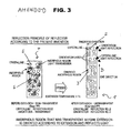
- one direction refers to a direction in which a sheet 4 is extended and the term “thickness direction” refers to a direction along the thickness of a sheet, which is perpendicular to the "one direction”. These directions are indicated in FIG. 3 .
- FIG. 3 illustrates the principle of reflection of a reflector manufactured of crystalline plastic according to an embodiment of the present invention.
- the reflector 1 includes a crystal region 2 and an amorphous region 3 which are mixed.
- the reflector 1 is manufactured by low-temperature extension of crystalline plastic at an extension temperature below a crystallization temperature Tc.
- the crystalline plastic maintains a semi-transparent state before extension.
- the crystal region 5 and crystals of the reflector material nitrogen PP
- the amorphous region 6 in which amorphous particles are irregularly arranged transmits light so that the overall reflector is in a semi-transparent state.
- the amorphous particles in the amorphous region 3 existing in a transformable state at a temperature below the crystallization temperature are oriented so that a plurality of orientation layers (indicated as lines in FIG. 3 ) are formed in the amorphous region 3.
- the extension is performed at a temperature below the crystallization temperature Tc, diffuse reflection occurs in the crystal region 2 in a reflection capability state.
- incident light is reflected by the orientation layers in the amorphous region 3 where no reflection has occurred, thus obtaining a high reflectance.
- the orientation layers are arranged in the predetermined direction D (please refer to FIG.
- the reflectance of the reflector 1 used in the present embodiment can be about 95% or more.
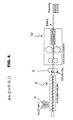
- FIG. 4 is a diagram for describing a method of manufacturing a reflector by low temperature extension of crystalline plastic, according to an embodiment of the present invention.
- the crystalline plastic material is preferably a polyester family such as PET (polyethylene terephthalate), PEN (polyethylene 2,6-naphthalate), or PNT (polybutylene terephthalate), or a polyolefin family such as PP (polypropylene), PE (polyethylene), HDPE (high density polyethylene), LDPE (low density polyethylene), or LLDPE (linear low density polyethylene).
- the UV stabilizer includes an organic based light stabilizer such as a hindered amine family, a salicylic acid family, a benzophenone family, a benzotriazole family, an anoacrylate family, a triazine family, a benzoate family, or an oxalic acid anilide family, and an inorganic based light stabilizer such as sol-gel. Detailed examples of the UV stabilizers are shown below.
- the type of the UV stabilizer that is added varies according to the specification of a reflector or the amount of the UV stabilizer can be appropriately determined within a range of 0.05 wt% through 5 wt%.
- the amount of the UV stabilizer is not greater than 0.05 wt%, a yellowing removal effect is degraded, which is not preferable.
- the amount of the stabilizer is not less than 5 wt%, the overall cost increases and strength is degraded, which is not preferable.
- the UV stabilizer is mixed with a crystalline plastic base member at an appropriate addition rate and the compound is extruded by an extrusion molder to mold an extrusion sheet 4.
- the extrusion sheet 4 exhausted from the extrusion molder 8 is cooled down at a temperature below the crystallization temperature of the crystalline plastic by passing through a cooling roll 9.
- the extrusion sheet 4 is input to an extension chamber 10 to extend the amorphous region such that amorphous particles in the amorphous region 6 can be oriented in one direction.
- the reflector 1 may be manufactured in a variety of forms according to the required product specifications such as the purpose of use, reflectance, thickness, and manufacturing costs of the reflector plate.
- the reflector 1 can be manufactured with only the operations of preparing a sheet 4 in a roll member formed of crystalline plastic from the start and inputting the prepared sheet to the extension chamber 10 at a temperature below the crystallization temperature Tc to extend the prepared sheet.
- the reflector 1 exhausted from the extension chamber 10 is slit according to the purpose of use/product specification. However, when a sheet 4 in a separate plate shape is input to the extension chamber, the slitting process can be omitted. Then, the reflector 1 is stacked according to a packaging standard, thus completing the reflector manufacturing process.
- Table 2 shows the comparison of major characteristics between an SPP (stretched polypropylene) reflector 1 manufactured using a low temperature extension method according to an embodiment of the present invention and conventional products.
- SPP product manufactured using the method of the present invention uses PP (polypropylene) as the crystalline plastic material.
- FIG. 5 is a 10,000 times magnified SEM (scanning electro-microscope) image of a section of the UX film of Teijin Dupont.
- arrows indicate BaSO 4 particles that are white pigments used as a 10-20% additive and circles indicate pores of about 1 to several micrometers in size generated around the additive due to the extension.
- the UX film obtains a desired reflectance according to the numbers of the BaSO 4 particles and pores.
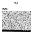
- FIG. 6 is a 1,000 times magnified SEM image of the MCPET product of Furukawa.
- MCPET image a large number of micro-bubbles having a size of tens of micrometers can be observed.
- the MCPET obtains a desired reflectance due to the micro-bubbles.
- FIG. 7 is a 10,000 times magnified SEM image of a section perpendicular to the extension direction of a PP material reflector 1 manufactured by low temperature extension at a temperature below a crystallization temperature, according to an embodiment of the present invention.
- FIG. 8 is a 1,000 times magnified SEM image of the same.
- FIG. 9 is a 10,000 times magnified SEM image of a section parallel to the extension direction of the PP material reflector manufactured by low temperature extension at a temperature below a crystallization temperature, according to an embodiment of the present invention.
- FIG. 8 compared to the MCPET product of FIG. 6 , spaces similar to micro-bubbles are not observed and a plurality of orientation layers formed in the amorphous region 3 are observed.
- the structure in which the orientation layers formed in the amorphous region are oriented in one direction becomes a major factor to determine the reflectance of a reflector of the present invention.
- FIG. 9 a structure in which pores are not observed and the amorphous region 3 is oriented can be clearly shown.
- pores can be observed in every section of the conventional reflectors shown in FIGS. 1 , 5 , and 6 , in the reflector of the present invention, pores are not observed at all in a section parallel to the extension direction.
- the orientation layers in a line shape formed in the amorphous region of the reflector of the present invention manufactured of the crystalline plastic material using the low temperature extension method is a major factor in determining the reflectance of the reflector of the present invention.
- FIG. 10 is a graph showing results of a test of the crystallization temperature of PP used as the crystalline plastic in an embodiment of the present invention.
- a circle indicates the crystallization temperature of the PP of 120°C.
- the crystallization temperatures of materials, for example, PET (polyethylene terephthalate) and PE (polyethylene) used as reflector materials in the present invention are 160.8°C and 70°C, respectively.
- PET polyethylene terephthalate
- PE polyethylene
- FIG. 11 is a graph showing the analysis of flowability of a crystalline plastic according to an embodiment of the present invention using differential scanning calorimetry (DSC).
- a melting temperature Tm is a temperature at which the crystalline plastic becomes liquid.
- the crystallization temperature Tc is a temperature at which crystallization is complete so that the crystalline plastic is in a completely solid state.
- a glass transition temperature Tg is a temperature at which an amorphous portion of the crystal plastic is melted.
- a sheet having a particular thickness is extruded and, before the sheet is completely hardened, that is, the temperature is dropped from the melting temperature Tm to the crystallization temperature Tc, the sheet is extended in a predetermined direction or in a direction perpendicular to the predetermined direction to manufacture a reflector.
- the low temperature extension manufacturing method according to the present invention a sheet 4 of a crystal material hardened at a temperature below Tc is extended.
- FIG. 12 is a photographic image showing the comparison of characteristics of a reflector product formed of PP material according to extension temperatures of 1.40°C, 150°C, 160°C, and 120°C from the left.
- the PP material extended at temperatures of 140°C, 150°C, and 160°C which are above the crystallization temperature (PP: 120°C) is formed to be wide, thin, and semitransparent like a conventional film.
- the PP material extended at 120°C on the right side of the image is formed to be relatively very small, white, and semitransparent. That is, when the PP material is extended at the temperatures of 140°C, 150°C, and 160°C above the crystallization temperature without an additive, the crystalline plastic is not suitable for use as a reflector.
- the amorphous particles in the amorphous region 3 are oriented in a predetermined direction and the orientation layers are formed so that a reflector 1 exhibiting superior reflectance can be obtained.
- sufficient reflectance can be obtained without the addition of a separate additive.
- FIG. 13 is a photographic image showing the results of different extensions of PP material at temperatures of 60°C, 80°C, and 100°C from the left, respectively.
- the tensile forces applied for each extension temperature are shown in Table 3 below.
- a reflector having a suitable final thickness to obtain a desired reflectance can be manufactured by appropriately selecting the extension temperature and the tensile force as an extension condition of an extension chamber according to the size and thickness of the original crystalline plastic material before the extension.
- FIG. 14 is a graph showing the total reflectance of a conventional MCPET product and reflectors formed of SPP (polypropylene) having various thicknesses manufactured according to an embodiment of the present invention.
- Table 4 shows the initial thickness of the SPP (polypropylene) materials before the extension and the final thickness of the reflectors 1 after the extension.
- the conventional MCPET product of Furukawa has a thickness of 0.94 mm and a total reflectance of 97.9% in the wavelength range of 550 nm at which visual cells are most excited.
- the thickness can be greatly reduced compared to the conventional product.
- a BLU (back light unit) of an LCD including the reflector of the present invention can be made compact.
- the reflector of the present invention can be used for not only TVs but also computer? monitors. Referring to the graph of FIG. 14 , the SPP 1.2 mm product of the present invention can obtain a total reflectance of 100.3%, and thus the brightness of an LCD product including the SPP 1.2 mm product can be greatly improved.
- FIG. 15 is a graph showing the diffuse reflectance of the conventional MCPET product and the reflectors 1 having various thicknesses manufactured according to an embodiment of the present invention.
- a reflector 1 having a superior diffuse reflectance is needed.
- a reflector SPP thin polypropylene having a thickness of 0.8 mm or more that is low-temperature extended using the reflector manufacturing method of the present invention has a diffuse reflectance higher than that of the conventional MCPET (Furukawa) 0.94 mm product. Also, it can be seen that even an SPP 0.5 mm product has a diffuse reflectance that is almost similar to that of the conventional MCPET product, in the wavelength range of 550 nm.
- a reflector 1 manufactured using the low temperature extension method according to the present invention can obtain a significantly higher reflectance at the same thickness than a conventional MCPET product having maximal reflectance. Even when the thickness is reduced from 0.94 mm to 0.5 mm, the substantially same reflectance can be obtained.
- orientation layers are arranged in a single predetermined direction only by performing mono-axial extension in one direction
- the orientation layers can be arranged together in the predetermined direction and a direction perpendicular to the predetermined direction by performing biaxial extension for the extension in both the predetermined direction and the direction perpendicular to the predetermined direction (for example, biaxial extension).
- orientation layers can be arranged in a thickness direction in which the crystalline plastic is pressed using a deep drawing process. That is, any structure in which orientation layers are formed in an amorphous region using a variety of methods is within the scope of the present invention.
Landscapes
- Physics & Mathematics (AREA)
- General Physics & Mathematics (AREA)
- Optics & Photonics (AREA)
- Engineering & Computer Science (AREA)
- General Engineering & Computer Science (AREA)
- Optical Elements Other Than Lenses (AREA)
- Laminated Bodies (AREA)
- Shaping By String And By Release Of Stress In Plastics And The Like (AREA)
- Extrusion Moulding Of Plastics Or The Like (AREA)
Priority Applications (1)
| Application Number | Priority Date | Filing Date | Title |
|---|---|---|---|
| PL07834255T PL2084561T3 (pl) | 2006-11-24 | 2007-11-23 | Odbłyśnik i sposób jego wytwarzania |
Applications Claiming Priority (2)
| Application Number | Priority Date | Filing Date | Title |
|---|---|---|---|
| KR1020060116649A KR100816126B1 (ko) | 2006-11-24 | 2006-11-24 | 반사판 제조방법 및 반사판 |
| PCT/KR2007/005957 WO2008063030A1 (en) | 2006-11-24 | 2007-11-23 | Reflector and manufacturing method thereof |
Publications (3)
| Publication Number | Publication Date |
|---|---|
| EP2084561A1 EP2084561A1 (en) | 2009-08-05 |
| EP2084561A4 EP2084561A4 (en) | 2012-01-04 |
| EP2084561B1 true EP2084561B1 (en) | 2014-08-20 |
Family
ID=39411477
Family Applications (1)
| Application Number | Title | Priority Date | Filing Date |
|---|---|---|---|
| EP20070834255 Not-in-force EP2084561B1 (en) | 2006-11-24 | 2007-11-23 | Reflector and manufacturing method thereof |
Country Status (8)
| Country | Link |
|---|---|
| US (2) | US8722190B2 (pl) |
| EP (1) | EP2084561B1 (pl) |
| JP (1) | JP4612738B2 (pl) |
| KR (1) | KR100816126B1 (pl) |
| CN (1) | CN101573638B (pl) |
| PL (1) | PL2084561T3 (pl) |
| RU (1) | RU2419112C2 (pl) |
| WO (1) | WO2008063030A1 (pl) |
Families Citing this family (2)
| Publication number | Priority date | Publication date | Assignee | Title |
|---|---|---|---|---|
| KR101221058B1 (ko) * | 2010-06-10 | 2013-01-11 | 에프티 주식회사 | 결정성을 가지는 고분자 연신기의 가이드 장치 |
| DE102014106549B4 (de) * | 2014-05-09 | 2023-10-19 | Pictiva Displays International Limited | Organisches Licht emittierendes Bauelement |
Family Cites Families (36)
| Publication number | Priority date | Publication date | Assignee | Title |
|---|---|---|---|---|
| KR850001241B1 (ko) * | 1983-08-05 | 1985-08-23 | 주식회사 삼양사 | 폴리에스텔섬유 염반사의 제조방법 |
| JPS6362104A (ja) | 1986-09-01 | 1988-03-18 | 株式会社明拓システム | 電飾用光源装置 |
| US5411805A (en) * | 1986-10-22 | 1995-05-02 | University Of Pittsburgh Of The Commonwealth System Of Higher Education | Triaxially oriented polymer membrane |
| JP3296021B2 (ja) | 1993-05-14 | 2002-06-24 | 東洋紡績株式会社 | 空洞含有ポリエステルフィルム |
| JP3622860B2 (ja) | 1993-10-27 | 2005-02-23 | 東洋紡績株式会社 | 配送伝票用ポリエステル系フィルム |
| US5760139A (en) * | 1994-04-18 | 1998-06-02 | Yasuhiro Koike | Graded-refractive-index optical plastic material and method for its production |
| DE69624077T2 (de) * | 1995-06-23 | 2003-06-12 | The Furukawa Electric Co., Ltd. | Lichtrefletkierende platte |
| JPH1045930A (ja) | 1996-08-01 | 1998-02-17 | Mitsui Petrochem Ind Ltd | ポリエステル樹脂光反射フィルムおよびその製造方法 |
| US6883938B1 (en) * | 1998-02-20 | 2005-04-26 | Nippon Zeon Co., Ltd. | Lighting equipment |
| US6449093B2 (en) * | 1999-10-12 | 2002-09-10 | 3M Innovative Properties Company | Optical bodies made with a birefringent polymer |
| TWI251089B (en) * | 2000-06-19 | 2006-03-11 | Nitto Denko Corp | Polarizer, polarizing plate, and liquid crystal display using the same |
| WO2002004996A1 (en) | 2000-07-12 | 2002-01-17 | Toray Industries, Inc. | White film for surface light source reflecting members |
| DE10111449A1 (de) | 2001-03-09 | 2002-09-26 | Schott Glas | Verwendung von bioaktivem Glas in Zahnfüllmaterial |
| KR100820278B1 (ko) | 2002-03-11 | 2008-04-07 | 엘지이노텍 주식회사 | 수정 진동자를 공용으로 사용하는 튜너 |
| KR100413102B1 (ko) | 2002-05-17 | 2003-12-31 | (주)이엠엘에스아이 | 동일뱅크 중복선택 방지 회로 |
| JP4143338B2 (ja) * | 2002-06-06 | 2008-09-03 | 株式会社ユポ・コーポレーション | 面光源装置および液晶ディスプレイ装置 |
| KR20050016992A (ko) | 2002-07-08 | 2005-02-21 | 코닌클리즈케 필립스 일렉트로닉스 엔.브이. | 전자 회로, 전자 회로 장치 및 상호 접속 테스트 방법 |
| JP3890005B2 (ja) | 2002-10-16 | 2007-03-07 | 古河電気工業株式会社 | 光反射板およびその製造方法 |
| KR20040046746A (ko) | 2002-11-28 | 2004-06-05 | 삼성전자주식회사 | 노광설비의 호환이 가능한 미스 얼라인 먼트 체크 방법 |
| KR100513033B1 (ko) | 2003-03-03 | 2005-09-05 | 엘지전자 주식회사 | 하부 발란서가 구비된 세탁기 |
| TWI237128B (en) * | 2003-05-15 | 2005-08-01 | Mitsui Chemicals Inc | Reflector, usage of relfector, and manufacture method of reflector |
| KR20040100558A (ko) | 2003-05-23 | 2004-12-02 | 엘지.필립스 엘시디 주식회사 | 횡전계 방식 액정표시장치의 제조방법 |
| KR20050010677A (ko) | 2003-07-22 | 2005-01-28 | 주식회사 하이닉스반도체 | 반도체 메모리 소자의 제조방법 |
| KR100555902B1 (ko) | 2003-08-05 | 2006-03-03 | 주식회사 대우일렉트로닉스 | Vcr/dvd 콤보 시스템에서 광픽업 이슬맺힘현상제거장치 |
| JP4379070B2 (ja) * | 2003-10-14 | 2009-12-09 | チッソ株式会社 | ポリオレフィン系光反射フィルム |
| KR100565743B1 (ko) | 2003-10-21 | 2006-03-29 | 엘지.필립스 엘시디 주식회사 | 백 라이트 유닛 |
| KR100965574B1 (ko) | 2003-11-21 | 2010-06-23 | 엘지디스플레이 주식회사 | 액정표시모듈 |
| KR20050056303A (ko) | 2003-12-10 | 2005-06-16 | 엘지.필립스 엘시디 주식회사 | 액정표시장치 백라이트 어셈블리 |
| TWI280417B (en) | 2004-01-09 | 2007-05-01 | Furukawa Electric Co Ltd | Light reflector |
| KR20050121578A (ko) | 2004-06-22 | 2005-12-27 | 삼성전자주식회사 | 백라이트 유닛 |
| JP4626757B2 (ja) * | 2004-07-14 | 2011-02-09 | 富士フイルム株式会社 | 熱可塑性フィルム及びその製造方法 |
| KR20060029391A (ko) | 2004-10-01 | 2006-04-06 | 삼성전자주식회사 | 광학 필름과, 이를 갖는 백라이트 어셈블리 및 표시 장치 |
| KR20060095361A (ko) | 2005-02-28 | 2006-08-31 | 엘지.필립스 엘시디 주식회사 | 백 라이트 유닛 및 이를 이용한 액정 표시 장치 |
| KR20060061932A (ko) | 2004-12-02 | 2006-06-09 | 삼성전자주식회사 | 액정 표시 장치 및 이의 제조 방법 |
| KR20060089434A (ko) | 2005-02-04 | 2006-08-09 | 삼성전자주식회사 | 백라이트 어셈블리 및 이를 갖는 표시장치 |
| JP2006251395A (ja) * | 2005-03-10 | 2006-09-21 | Daicel Chem Ind Ltd | 異方性散乱シート |
-
2006
- 2006-11-24 KR KR1020060116649A patent/KR100816126B1/ko not_active Expired - Fee Related
-
2007
- 2007-11-23 JP JP2009538334A patent/JP4612738B2/ja not_active Expired - Fee Related
- 2007-11-23 US US12/513,133 patent/US8722190B2/en not_active Expired - Fee Related
- 2007-11-23 WO PCT/KR2007/005957 patent/WO2008063030A1/en not_active Ceased
- 2007-11-23 EP EP20070834255 patent/EP2084561B1/en not_active Not-in-force
- 2007-11-23 RU RU2009123398/28A patent/RU2419112C2/ru not_active IP Right Cessation
- 2007-11-23 CN CN2007800435035A patent/CN101573638B/zh not_active Expired - Fee Related
- 2007-11-23 PL PL07834255T patent/PL2084561T3/pl unknown
-
2012
- 2012-07-26 US US13/559,586 patent/US20130184403A1/en not_active Abandoned
Also Published As
| Publication number | Publication date |
|---|---|
| US8722190B2 (en) | 2014-05-13 |
| HK1138380A1 (en) | 2010-08-20 |
| CN101573638B (zh) | 2011-10-26 |
| JP2010511188A (ja) | 2010-04-08 |
| JP4612738B2 (ja) | 2011-01-12 |
| CN101573638A (zh) | 2009-11-04 |
| RU2419112C2 (ru) | 2011-05-20 |
| WO2008063030A1 (en) | 2008-05-29 |
| EP2084561A4 (en) | 2012-01-04 |
| EP2084561A1 (en) | 2009-08-05 |
| KR100816126B1 (ko) | 2008-03-21 |
| US20100254012A1 (en) | 2010-10-07 |
| RU2009123398A (ru) | 2010-12-27 |
| PL2084561T3 (pl) | 2015-02-27 |
| US20130184403A1 (en) | 2013-07-18 |
Similar Documents
| Publication | Publication Date | Title |
|---|---|---|
| TWI400164B (zh) | 白色聚酯薄膜 | |
| KR100200200B1 (ko) | 광반사체 및 광반사장치 | |
| KR101247233B1 (ko) | 백색 폴리에스테르 필름 및 그것을 사용한 면광원 | |
| TWI441852B (zh) | 白色薄膜及使用它之面光源 | |
| JP5033625B2 (ja) | 発泡樹脂シートおよび液晶表示装置 | |
| JP2002090515A (ja) | 面光源反射部材用白色フィルム | |
| CN101084458B (zh) | 光反射体及使用该光反射体的面光源装置 | |
| CN1938614B (zh) | 反射板及其制备方法 | |
| JP2002050222A (ja) | 面光源反射板用白色フィルム | |
| JP5391618B2 (ja) | 白色フィルムおよびそれを用いた面光源 | |
| CN1985192A (zh) | 光反射体及使用该光反射体的面光源装置 | |
| EP2084561B1 (en) | Reflector and manufacturing method thereof | |
| CN100492128C (zh) | 面光源装置及液晶显示装置 | |
| US20070188681A1 (en) | Liquid crystal display | |
| JP2001228313A (ja) | 面光源反射部材用白色積層ポリエステルフィルム | |
| JP2007140542A (ja) | 光反射フィルムとそれを用いた面光源 | |
| JP2014065817A (ja) | 2軸延伸フィルム | |
| HK1138380B (en) | Reflector and manufacturing method thereof | |
| KR100844884B1 (ko) | 고백색도의 미연신 반사시트 및 그의 제조방법 | |
| JP2004271567A (ja) | 光拡散性シートおよび直下型バックライト | |
| JP2008069217A (ja) | ポリエステルフィルムおよびその製造方法。 | |
| JP2013113872A (ja) | 反射フィルム及び反射材 |
Legal Events
| Date | Code | Title | Description |
|---|---|---|---|
| PUAI | Public reference made under article 153(3) epc to a published international application that has entered the european phase |
Free format text: ORIGINAL CODE: 0009012 |
|
| 17P | Request for examination filed |
Effective date: 20090430 |
|
| AK | Designated contracting states |
Kind code of ref document: A1 Designated state(s): AT BE BG CH CY CZ DE DK EE ES FI FR GB GR HU IE IS IT LI LT LU LV MC MT NL PL PT RO SE SI SK TR |
|
| DAX | Request for extension of the european patent (deleted) | ||
| A4 | Supplementary search report drawn up and despatched |
Effective date: 20111207 |
|
| RIC1 | Information provided on ipc code assigned before grant |
Ipc: G02B 5/08 20060101AFI20111201BHEP |
|
| 17Q | First examination report despatched |
Effective date: 20121012 |
|
| RIC1 | Information provided on ipc code assigned before grant |
Ipc: G02B 5/08 20060101AFI20131021BHEP |
|
| GRAP | Despatch of communication of intention to grant a patent |
Free format text: ORIGINAL CODE: EPIDOSNIGR1 |
|
| INTG | Intention to grant announced |
Effective date: 20140318 |
|
| RIN1 | Information on inventor provided before grant (corrected) |
Inventor name: YOON, JAE-DONG |
|
| GRAS | Grant fee paid |
Free format text: ORIGINAL CODE: EPIDOSNIGR3 |
|
| GRAA | (expected) grant |
Free format text: ORIGINAL CODE: 0009210 |
|
| AK | Designated contracting states |
Kind code of ref document: B1 Designated state(s): AT BE BG CH CY CZ DE DK EE ES FI FR GB GR HU IE IS IT LI LT LU LV MC MT NL PL PT RO SE SI SK TR |
|
| REG | Reference to a national code |
Ref country code: GB Ref legal event code: FG4D |
|
| REG | Reference to a national code |
Ref country code: CH Ref legal event code: EP |
|
| REG | Reference to a national code |
Ref country code: AT Ref legal event code: REF Ref document number: 683761 Country of ref document: AT Kind code of ref document: T Effective date: 20140915 |
|
| REG | Reference to a national code |
Ref country code: IE Ref legal event code: FG4D |
|
| REG | Reference to a national code |
Ref country code: DE Ref legal event code: R096 Ref document number: 602007038257 Country of ref document: DE Effective date: 20141002 |
|
| REG | Reference to a national code |
Ref country code: AT Ref legal event code: MK05 Ref document number: 683761 Country of ref document: AT Kind code of ref document: T Effective date: 20140820 |
|
| REG | Reference to a national code |
Ref country code: NL Ref legal event code: VDEP Effective date: 20140820 |
|
| REG | Reference to a national code |
Ref country code: LT Ref legal event code: MG4D |
|
| PG25 | Lapsed in a contracting state [announced via postgrant information from national office to epo] |
Ref country code: PT Free format text: LAPSE BECAUSE OF FAILURE TO SUBMIT A TRANSLATION OF THE DESCRIPTION OR TO PAY THE FEE WITHIN THE PRESCRIBED TIME-LIMIT Effective date: 20141222 Ref country code: GR Free format text: LAPSE BECAUSE OF FAILURE TO SUBMIT A TRANSLATION OF THE DESCRIPTION OR TO PAY THE FEE WITHIN THE PRESCRIBED TIME-LIMIT Effective date: 20141121 Ref country code: ES Free format text: LAPSE BECAUSE OF FAILURE TO SUBMIT A TRANSLATION OF THE DESCRIPTION OR TO PAY THE FEE WITHIN THE PRESCRIBED TIME-LIMIT Effective date: 20140820 Ref country code: BG Free format text: LAPSE BECAUSE OF FAILURE TO SUBMIT A TRANSLATION OF THE DESCRIPTION OR TO PAY THE FEE WITHIN THE PRESCRIBED TIME-LIMIT Effective date: 20141120 Ref country code: SE Free format text: LAPSE BECAUSE OF FAILURE TO SUBMIT A TRANSLATION OF THE DESCRIPTION OR TO PAY THE FEE WITHIN THE PRESCRIBED TIME-LIMIT Effective date: 20140820 Ref country code: LT Free format text: LAPSE BECAUSE OF FAILURE TO SUBMIT A TRANSLATION OF THE DESCRIPTION OR TO PAY THE FEE WITHIN THE PRESCRIBED TIME-LIMIT Effective date: 20140820 Ref country code: FI Free format text: LAPSE BECAUSE OF FAILURE TO SUBMIT A TRANSLATION OF THE DESCRIPTION OR TO PAY THE FEE WITHIN THE PRESCRIBED TIME-LIMIT Effective date: 20140820 |
|
| PG25 | Lapsed in a contracting state [announced via postgrant information from national office to epo] |
Ref country code: IS Free format text: LAPSE BECAUSE OF FAILURE TO SUBMIT A TRANSLATION OF THE DESCRIPTION OR TO PAY THE FEE WITHIN THE PRESCRIBED TIME-LIMIT Effective date: 20141220 Ref country code: AT Free format text: LAPSE BECAUSE OF FAILURE TO SUBMIT A TRANSLATION OF THE DESCRIPTION OR TO PAY THE FEE WITHIN THE PRESCRIBED TIME-LIMIT Effective date: 20140820 Ref country code: LV Free format text: LAPSE BECAUSE OF FAILURE TO SUBMIT A TRANSLATION OF THE DESCRIPTION OR TO PAY THE FEE WITHIN THE PRESCRIBED TIME-LIMIT Effective date: 20140820 |
|
| REG | Reference to a national code |
Ref country code: PL Ref legal event code: T3 |
|
| PG25 | Lapsed in a contracting state [announced via postgrant information from national office to epo] |
Ref country code: NL Free format text: LAPSE BECAUSE OF FAILURE TO SUBMIT A TRANSLATION OF THE DESCRIPTION OR TO PAY THE FEE WITHIN THE PRESCRIBED TIME-LIMIT Effective date: 20140820 |
|
| PG25 | Lapsed in a contracting state [announced via postgrant information from national office to epo] |
Ref country code: RO Free format text: LAPSE BECAUSE OF FAILURE TO SUBMIT A TRANSLATION OF THE DESCRIPTION OR TO PAY THE FEE WITHIN THE PRESCRIBED TIME-LIMIT Effective date: 20140820 Ref country code: DK Free format text: LAPSE BECAUSE OF FAILURE TO SUBMIT A TRANSLATION OF THE DESCRIPTION OR TO PAY THE FEE WITHIN THE PRESCRIBED TIME-LIMIT Effective date: 20140820 Ref country code: EE Free format text: LAPSE BECAUSE OF FAILURE TO SUBMIT A TRANSLATION OF THE DESCRIPTION OR TO PAY THE FEE WITHIN THE PRESCRIBED TIME-LIMIT Effective date: 20140820 Ref country code: SK Free format text: LAPSE BECAUSE OF FAILURE TO SUBMIT A TRANSLATION OF THE DESCRIPTION OR TO PAY THE FEE WITHIN THE PRESCRIBED TIME-LIMIT Effective date: 20140820 Ref country code: CZ Free format text: LAPSE BECAUSE OF FAILURE TO SUBMIT A TRANSLATION OF THE DESCRIPTION OR TO PAY THE FEE WITHIN THE PRESCRIBED TIME-LIMIT Effective date: 20140820 |
|
| REG | Reference to a national code |
Ref country code: DE Ref legal event code: R097 Ref document number: 602007038257 Country of ref document: DE |
|
| PLBE | No opposition filed within time limit |
Free format text: ORIGINAL CODE: 0009261 |
|
| STAA | Information on the status of an ep patent application or granted ep patent |
Free format text: STATUS: NO OPPOSITION FILED WITHIN TIME LIMIT |
|
| PG25 | Lapsed in a contracting state [announced via postgrant information from national office to epo] |
Ref country code: BE Free format text: LAPSE BECAUSE OF NON-PAYMENT OF DUE FEES Effective date: 20141130 Ref country code: LU Free format text: LAPSE BECAUSE OF FAILURE TO SUBMIT A TRANSLATION OF THE DESCRIPTION OR TO PAY THE FEE WITHIN THE PRESCRIBED TIME-LIMIT Effective date: 20141123 Ref country code: MC Free format text: LAPSE BECAUSE OF FAILURE TO SUBMIT A TRANSLATION OF THE DESCRIPTION OR TO PAY THE FEE WITHIN THE PRESCRIBED TIME-LIMIT Effective date: 20140820 |
|
| REG | Reference to a national code |
Ref country code: CH Ref legal event code: PL |
|
| 26N | No opposition filed |
Effective date: 20150521 |
|
| PG25 | Lapsed in a contracting state [announced via postgrant information from national office to epo] |
Ref country code: LI Free format text: LAPSE BECAUSE OF NON-PAYMENT OF DUE FEES Effective date: 20141130 Ref country code: CH Free format text: LAPSE BECAUSE OF NON-PAYMENT OF DUE FEES Effective date: 20141130 |
|
| REG | Reference to a national code |
Ref country code: IE Ref legal event code: MM4A |
|
| PG25 | Lapsed in a contracting state [announced via postgrant information from national office to epo] |
Ref country code: IE Free format text: LAPSE BECAUSE OF NON-PAYMENT OF DUE FEES Effective date: 20141123 |
|
| REG | Reference to a national code |
Ref country code: FR Ref legal event code: PLFP Year of fee payment: 9 |
|
| PG25 | Lapsed in a contracting state [announced via postgrant information from national office to epo] |
Ref country code: SI Free format text: LAPSE BECAUSE OF FAILURE TO SUBMIT A TRANSLATION OF THE DESCRIPTION OR TO PAY THE FEE WITHIN THE PRESCRIBED TIME-LIMIT Effective date: 20140820 |
|
| PG25 | Lapsed in a contracting state [announced via postgrant information from national office to epo] |
Ref country code: CY Free format text: LAPSE BECAUSE OF FAILURE TO SUBMIT A TRANSLATION OF THE DESCRIPTION OR TO PAY THE FEE WITHIN THE PRESCRIBED TIME-LIMIT Effective date: 20140820 |
|
| PG25 | Lapsed in a contracting state [announced via postgrant information from national office to epo] |
Ref country code: BE Free format text: LAPSE BECAUSE OF FAILURE TO SUBMIT A TRANSLATION OF THE DESCRIPTION OR TO PAY THE FEE WITHIN THE PRESCRIBED TIME-LIMIT Effective date: 20140820 Ref country code: TR Free format text: LAPSE BECAUSE OF FAILURE TO SUBMIT A TRANSLATION OF THE DESCRIPTION OR TO PAY THE FEE WITHIN THE PRESCRIBED TIME-LIMIT Effective date: 20140820 Ref country code: HU Free format text: LAPSE BECAUSE OF FAILURE TO SUBMIT A TRANSLATION OF THE DESCRIPTION OR TO PAY THE FEE WITHIN THE PRESCRIBED TIME-LIMIT; INVALID AB INITIO Effective date: 20071123 Ref country code: MT Free format text: LAPSE BECAUSE OF FAILURE TO SUBMIT A TRANSLATION OF THE DESCRIPTION OR TO PAY THE FEE WITHIN THE PRESCRIBED TIME-LIMIT Effective date: 20140820 |
|
| REG | Reference to a national code |
Ref country code: DE Ref legal event code: R082 Ref document number: 602007038257 Country of ref document: DE Representative=s name: KEILITZ HAINES & PARTNER PATENTANWAELTE PARTGM, DE Ref country code: DE Ref legal event code: R082 Ref document number: 602007038257 Country of ref document: DE Representative=s name: PATENTANWAELTE KEILITZ & PARTNER, PARTNERSCHAF, DE |
|
| REG | Reference to a national code |
Ref country code: FR Ref legal event code: PLFP Year of fee payment: 10 |
|
| PGFP | Annual fee paid to national office [announced via postgrant information from national office to epo] |
Ref country code: DE Payment date: 20161125 Year of fee payment: 10 Ref country code: GB Payment date: 20161124 Year of fee payment: 10 Ref country code: FR Payment date: 20161124 Year of fee payment: 10 |
|
| PGFP | Annual fee paid to national office [announced via postgrant information from national office to epo] |
Ref country code: IT Payment date: 20161124 Year of fee payment: 10 Ref country code: PL Payment date: 20161115 Year of fee payment: 10 |
|
| REG | Reference to a national code |
Ref country code: DE Ref legal event code: R119 Ref document number: 602007038257 Country of ref document: DE |
|
| GBPC | Gb: european patent ceased through non-payment of renewal fee |
Effective date: 20171123 |
|
| REG | Reference to a national code |
Ref country code: FR Ref legal event code: ST Effective date: 20180731 |
|
| PG25 | Lapsed in a contracting state [announced via postgrant information from national office to epo] |
Ref country code: FR Free format text: LAPSE BECAUSE OF NON-PAYMENT OF DUE FEES Effective date: 20171130 Ref country code: IT Free format text: LAPSE BECAUSE OF NON-PAYMENT OF DUE FEES Effective date: 20171123 Ref country code: DE Free format text: LAPSE BECAUSE OF NON-PAYMENT OF DUE FEES Effective date: 20180602 |
|
| PG25 | Lapsed in a contracting state [announced via postgrant information from national office to epo] |
Ref country code: GB Free format text: LAPSE BECAUSE OF NON-PAYMENT OF DUE FEES Effective date: 20171123 |
|
| PG25 | Lapsed in a contracting state [announced via postgrant information from national office to epo] |
Ref country code: PL Free format text: LAPSE BECAUSE OF NON-PAYMENT OF DUE FEES Effective date: 20171123 |