EP2085149A1 - Vibrateur pour un appareil de fonçage vibratoire - Google Patents
Vibrateur pour un appareil de fonçage vibratoire Download PDFInfo
- Publication number
- EP2085149A1 EP2085149A1 EP08001601A EP08001601A EP2085149A1 EP 2085149 A1 EP2085149 A1 EP 2085149A1 EP 08001601 A EP08001601 A EP 08001601A EP 08001601 A EP08001601 A EP 08001601A EP 2085149 A1 EP2085149 A1 EP 2085149A1
- Authority
- EP
- European Patent Office
- Prior art keywords
- vibration generator
- sensor
- detecting
- generator according
- acceleration
- Prior art date
- Legal status (The legal status is an assumption and is not a legal conclusion. Google has not performed a legal analysis and makes no representation as to the accuracy of the status listed.)
- Granted
Links
Images
Classifications
-
- B—PERFORMING OPERATIONS; TRANSPORTING
- B06—GENERATING OR TRANSMITTING MECHANICAL VIBRATIONS IN GENERAL
- B06B—METHODS OR APPARATUS FOR GENERATING OR TRANSMITTING MECHANICAL VIBRATIONS OF INFRASONIC, SONIC, OR ULTRASONIC FREQUENCY, e.g. FOR PERFORMING MECHANICAL WORK IN GENERAL
- B06B1/00—Methods or apparatus for generating mechanical vibrations of infrasonic, sonic, or ultrasonic frequency
- B06B1/10—Methods or apparatus for generating mechanical vibrations of infrasonic, sonic, or ultrasonic frequency making use of mechanical energy
- B06B1/16—Methods or apparatus for generating mechanical vibrations of infrasonic, sonic, or ultrasonic frequency making use of mechanical energy operating with systems involving rotary unbalanced masses
- B06B1/161—Adjustable systems, i.e. where amplitude or direction of frequency of vibration can be varied
- B06B1/166—Where the phase-angle of masses mounted on counter-rotating shafts can be varied, e.g. variation of the vibration phase
-
- E—FIXED CONSTRUCTIONS
- E02—HYDRAULIC ENGINEERING; FOUNDATIONS; SOIL SHIFTING
- E02D—FOUNDATIONS; EXCAVATIONS; EMBANKMENTS; UNDERGROUND OR UNDERWATER STRUCTURES
- E02D7/00—Methods or apparatus for placing sheet pile bulkheads, piles, mouldpipes, or other moulds
- E02D7/18—Placing by vibrating
Definitions
- the invention relates to a vibration generator for a vibratory pile driver according to the preamble of claim 1.
- the invention further relates to a vibratory pile driver according to claim 9.
- vibrators are used to bring objects such as profiles into the ground or to pull them out of the ground or to compact soil material.
- the soil is stimulated by vibration and thus reaches a "pseudo-liquid" state.
- the vibration is characterized by a linear movement and is generated by pairwise counter-rotating imbalances within a Vibratorgetriebes.
- Vibration generators are characterized by the rotating unbalance and the maximum speed.
- the vibration generators are linear vibration exciters whose centrifugal force is generated by rotating imbalances. These vibration exciters move at a variable speed. The size of the imbalance is also called "static moment". The course of the velocity of the linear vibration exciter corresponds to a periodically recurring function, for example a sine function, but it can also take other forms.
- Vibration generators are operated by hydraulic drives, which set the waves on which the imbalances are arranged in rotation.
- Such hydraulic drives have a power curve, which is dependent on the operating speed and the operating pressure. With the same drive power is achieved by a lower speed, a higher static torque, which at the same time a higher ground vibration is effected. In the inner city area floor vibrations are to be avoided. These can be reduced by operating at a higher speed, but at the same time reducing the static torque. These measures prove to be problematic because the required drive power and torque are speed dependent. If the optimum operating speed range of the hydraulic drive or motor is left, this results in a power loss. Likewise, the torque required on the engine decreases as the pile mass increases. Accordingly, the pressure gradient decreases on the engine and the offered drive power can only be partially used.
- the invention aims to remedy this situation.
- the invention is based on the object to provide a vibration generator that allows operation in different speed ranges without power loss. According to the invention, this object is solved by the features of the characterizing part of patent claim 1.
- a vibration generator is provided which allows operation in different speed ranges without power loss.
- a hydraulic drive with variable displacement makes it possible to adapt the power curve to the required speed range. A power loss of the drive is counteracted by this.
- the term "displacement volume” refers to the amount of hydraulic fluid consumed by the hydraulic drive per revolution.
- the power delivered by a hydraulic drive is directly proportional to the displacement, the speed and the pressure gradient.
- the product of the displacement and the speed results in the volume flow.
- the pressure gradient is the difference between the pressure of the incoming hydraulic fluid (which is usually the pump pressure) and the pressure of the hydraulic fluid (which is usually the tank pressure).
- a control module is provided, via which the absorption volume can be set as a function of operating pressure or rotational speed. This allows a continuous adjustment of the power curve of the hydraulic drive, whereby the vibrator optimally uses the offered power.
- a limit operating pressure or a limit speed is adjustable. This makes it possible to set a defined operating state in which a change in the absorption volume is to be initiated.
- a control and regulating circuit which comprises a storage unit for depositing soil condition or task-specific default data sets with defined operating characteristics, from which a respective required record is selectable, sensors for continuously recording the defined operating characteristics, an evaluation unit for comparing the determined operating characteristics with the operating characteristics of the selected default data set, a control device coupled to the evaluation unit for controlling the vibration generator, and a control device coupled to the control device for controlling the means for Adjustment of the relative rotational position of the imbalance masses to each other.
- control module for adjusting the absorption volume is integrated in the drive.
- control module can be integrated in the control and regulating circuit.
- sensors for detecting the frequency, the static load and the relative position of the imbalance masses are arranged to each other.
- the sensors comprise at least one inductive sensor and / or a rotary encoder.
- Such sensors have proven to be durable and robust.
- a sensor for detecting the acceleration of the rotating shafts is arranged.
- a sensor for detecting the amplitude of the oscillations of the vibration generator can be arranged.
- a device for the automatic selection of a default data set on the basis of the determined acceleration values is provided.
- a program automation can be implemented, by means of which, depending on the task-specific operating situation, the automatic selection of the most efficient predefined variables takes place, without intervention by the operator being necessary.
- a semi-automatic can be realized in which the operator an operating characteristic data record is proposed, which can be confirmed or changed by the operator.
- the evaluation unit advantageously has a programmable logic controller (PLC). This allows flexible control of the vibration generator.
- PLC programmable logic controller
- an acoustic and / or visual warning device for alerting incorrect inputs, which is connected to the evaluation unit. In this way, the operator can be notified of a required adaptation or change of the current operating parameters.
- the invention is further based on the object to provide a Vibratoryramm réelle that allows operation in different speed ranges without power loss. According to the invention, this object is solved by the features of claim 9.
- a vibration racking device which allows operation in different speed ranges without power loss.
- a sensor for detecting the forces acting on the pile material forces is arranged. By determining this size, a characterization of the soil condition is possible. This characterization can be improved by the preferred arrangement of at least one sensor which can be applied to the penetration medium for detecting the vibrations of the penetration medium, which is connected to the evaluation unit. Preferably, a sensor for detecting the penetration rate of the pile is provided.
- a device for automatic selection of a default data set on the basis of the determined forces acting on the pile material and / or the determined Rammgut Irish and acceleration and / or the detected vibrations of the penetration medium is provided.
- a program automation can be implemented, by means of which, depending on the task-specific operating situation, the automatic selection of the most efficient predefined variables takes place, without intervention by the operator being necessary.
- a semi-automatic can be realized in which the operator an operating characteristics record is proposed, which can be confirmed or changed by the operator.
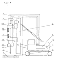
- the vibration ramming device chosen as an exemplary embodiment consists essentially of a carrier device 1, on which a vibrator (vibrator) 3 is arranged so as to be vertically displaceable via a broker 2.
- the vibration generator 3 comprises a housing 31, which is surrounded by a hood 30. On the hood 30, a clamping tongs 37 for receiving pile material 4 is arranged.
- the hood 30 serves to guide the vibration generator 3 and transmits the static force of the leader 2 to the vibration generator 3.
- the vibration generator 3 generates a vibration via rotating unbalances 3311, 3321, 3331, 3511, 3521, 3531, which is transmitted via the clamping tongs 33 on the Rammgut 4 is transmitted.
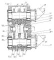
- the vibrator 3 is designed as a vibrator gearbox ( FIG. 2 ). It consists essentially of a housing 31, in which with gears 331, 332, 333, 351, 352, 353 provided shafts 33, 35 are rotatably mounted.
- the gears 331, 332, 333, 351, 352, 353 are each provided with unbalanced masses 3311, 3321, 3331, 3511, 3521, 3531, wherein the gears of both shafts 33, 35 via gears 3613, 3614 of the rotor shaft 361 of a pivot motor 36 with each other are engaged.
- the gears 331, 3321, 3331, 3511, 3521, 3531 provided with unbalanced masses 331, 332, 333, 351, 352, 353 are adjustable relative to each other via the pivot motor 36 in its rotational position, whereby the resulting imbalance or the resulting static moment is adjustable.
- the vibrator 3 is opposite to the gears 331, 332, 333, 351, 352, 353 provided on the inside of the housing 31 each with two parallel to the circumference of the gears spaced from each other arranged inductive sensors 310.
- the inductive sensors 310 enable the detection of the angular acceleration of the rotating imbalance masses 3311, 3321, 3331, 3511, 3521, 3531.
- the time offset of the imbalance masses 3311, 3321, 3331, 3511, 3521, 3531 can furthermore be used to determine their relative position to one another.
- an acceleration sensor 311 is arranged on the housing 31 of the vibration generator 3.
- a programmable logic controller (PLC) 7 is arranged as the evaluation unit, which further calculates the respectively applied static moment on the basis of frequency and time offset of the imbalance masses.
- PLC programmable logic controller
- the shafts 33, 35 of the vibrator 3 are connected to hydraulic drives 38, which have a variable displacement.
- hydraulic drives 38 are known in different designs.
- the hydraulic drives 38 are connected to a control module, via which the displacement is adjustable in dependence on the respective operating speed range.
- the control module is integrated in the drive 38.
- the PLC 7 is preceded by a memory unit 10, which is connected via lines 6 to the PLC 7.
- soil constitution specific default data sets are stored with defined operating characteristics. These default values are empirically determined quantities.
- the data sets are coupled to force and acceleration values to be determined, which are transmitted as input variables of the PLC 7.
- the vibration emission of the surrounding penetrating medium is deposited as the influencing variable.
- the force and acceleration values are determined via a force sensor 52 and an acceleration sensor 311.
- the force sensor 52 is set up such that it exerts the forces acting on the pile 4, the forces applied by the leader 2 and the counterforce generated by the penetration medium results, determined and transmitted via lines 6 to the PLC 7.
- the acceleration sensor 311 is set up in such a way that it determines the penetration speed and acceleration of the pile material 4 into the penetration medium 9 and also transmits them via lines 6 to the SPS 7.
- the penetration rate can be determined with an additional sensor (53), preferably a laser for distance measurement between the vibrator and the ground.
- the determination of the applied force can also take place via an acceleration sensor 311 and the dynamic mass.
- a vibration sensor 54 is applied to the floor 9 at a distance from the location of penetration of the pile material 4. This vibration sensor 54 detects the vibrations emitted by the ground during the pile-driving operation from the ground 9 and transmits the detected vibration values to the PLC 7 via a line 6.
- a default data set assigned to these values is selected from a memory unit 10 whose default values are to be compared with those by the sensors 310 , 311 determined operating parameters are used.
- the selection of a data set by the operator of the vibratory pile driver via a corresponding control panel possible.
- a controller 8 is arranged, which is connected via lines 6 to the memory unit 10 and to the PLC 7.
- the controller 8 is set up in such a way that it calculates the optimum operating parameters of the vibration generator from the static torque determined by the SPS 7 and the acceleration data determined by the sensors 311 against the background of the default characteristic values of the default data set selected from the memory unit 10.
- the controller 8 is connected to the arranged in the vibrator 3 pivot motor 36 for changing the relative rotational position of the imbalance masses to each other.
- the current operating characteristics recorded by the sensors 310, 311 are adapted to the corresponding preset values of the selected default data set.
- an adjustment of the resulting imbalance or the resulting static torque In the case of exceeding the permissible acceleration values via the pivot motor 36 via the gear 3621 an adjustment of the resulting imbalance or the resulting static torque.
- an optical and / or acoustic signal in the operator's stand of the carrier device is possible to inform the operator of the significant exceeding of allowable acceleration values.
- this indicates the selection of an unsuitable operating characteristic quantity set from the memory unit 10. Enabling the signal instructs the operator to review and, if necessary, correct the selection of the default data set.
Landscapes
- Engineering & Computer Science (AREA)
- Life Sciences & Earth Sciences (AREA)
- General Life Sciences & Earth Sciences (AREA)
- Mining & Mineral Resources (AREA)
- Paleontology (AREA)
- Civil Engineering (AREA)
- General Engineering & Computer Science (AREA)
- Structural Engineering (AREA)
- Mechanical Engineering (AREA)
- Placing Or Removing Of Piles Or Sheet Piles, Or Accessories Thereof (AREA)
Priority Applications (3)
| Application Number | Priority Date | Filing Date | Title |
|---|---|---|---|
| DE200820017313 DE202008017313U1 (de) | 2008-01-29 | 2008-01-29 | Schwingungserzeuger für Vibrationsrammgerät |
| EP08001601.7A EP2085149B2 (fr) | 2008-01-29 | 2008-01-29 | Vibrateur pour un appareil de fonçage vibratoire |
| US12/290,104 US8522891B2 (en) | 2008-01-29 | 2008-10-27 | Vibration generator for a vibration pile driver |
Applications Claiming Priority (1)
| Application Number | Priority Date | Filing Date | Title |
|---|---|---|---|
| EP08001601.7A EP2085149B2 (fr) | 2008-01-29 | 2008-01-29 | Vibrateur pour un appareil de fonçage vibratoire |
Publications (3)
| Publication Number | Publication Date |
|---|---|
| EP2085149A1 true EP2085149A1 (fr) | 2009-08-05 |
| EP2085149B1 EP2085149B1 (fr) | 2013-07-24 |
| EP2085149B2 EP2085149B2 (fr) | 2021-12-22 |
Family
ID=39365417
Family Applications (1)
| Application Number | Title | Priority Date | Filing Date |
|---|---|---|---|
| EP08001601.7A Active EP2085149B2 (fr) | 2008-01-29 | 2008-01-29 | Vibrateur pour un appareil de fonçage vibratoire |
Country Status (2)
| Country | Link |
|---|---|
| US (1) | US8522891B2 (fr) |
| EP (1) | EP2085149B2 (fr) |
Cited By (8)
| Publication number | Priority date | Publication date | Assignee | Title |
|---|---|---|---|---|
| EP2557233A1 (fr) | 2011-08-12 | 2013-02-13 | ABI Anlagentechnik-Baumaschinen-Industriebedarf Maschinenfabrik und Vertriebsgesellschaft mbH | Appareil de travail doté d'un entraînement hydraulique pour travaux de construction profonds |
| EP2789402A1 (fr) * | 2013-04-10 | 2014-10-15 | ABI Anlagentechnik-Baumaschinen-Industriebedarf Maschinenfabrik und Vertriebsgesellschaft mbH | Accélérateur d'oscillations |
| US9289799B2 (en) | 2013-04-10 | 2016-03-22 | Abi Anlagentechnik-Baumaschinen-Industriebedarf Maschinenfabrik Und Vertriebsgesellschaft Mbh | Vibration exciter for construction machines |
| EP3243573A1 (fr) | 2016-05-09 | 2017-11-15 | Eurodrill GmbH | Dispositif de production de vibrations |
| US10385883B2 (en) | 2013-04-12 | 2019-08-20 | Thyssenkrupp Infrastructure Gmbh | Vibrating ram arrangement, and method for operating the vibrating ram arrangement |
| EP4528035A1 (fr) * | 2023-09-19 | 2025-03-26 | Liebherr-Werk Nenzing GmbH | Procédé de surveillance d'une machine de travail dotée d'un veau et machine de travail dotée d'un veau |
| EP4671449A1 (fr) | 2024-06-26 | 2025-12-31 | ABI Anlagentechnik-Baumaschinen-Industriebedarf Maschinenfabrik und Vertriebsgesellschaft mbH | Dispositif et procédé de sécurisation d'un élément de construction souterraine sur une machine de construction souterraine |
| EP4675047A1 (fr) | 2024-07-03 | 2026-01-07 | ABI Anlagentechnik-Baumaschinen-Industriebedarf Maschinenfabrik und Vertriebsgesellschaft mbH | Générateur de vibrations pour sonnettes mécaniques vibrantes |
Families Citing this family (8)
| Publication number | Priority date | Publication date | Assignee | Title |
|---|---|---|---|---|
| EP2085148B1 (fr) * | 2008-01-29 | 2013-09-18 | ABI Anlagentechnik-Baumaschinen-Industriebedarf Maschinenfabrik und Vertriebsgesellschaft mbH | Vibrateur pour un appareil de fonçage vibratoire |
| EP3101179B1 (fr) | 2015-06-03 | 2018-04-18 | ABI Anlagentechnik-Baumaschinen-Industriebedarf Maschinenfabrik und Vertriebsgesellschaft mbH | Appareil de travail, notamment pour un engin de chantier |
| DE102015008015A1 (de) * | 2015-06-22 | 2016-12-22 | Liebherr-Werk Nenzing Gmbh | Verfahren zum Steuern einer Vibrationsramme |
| MY190434A (en) * | 2015-10-12 | 2022-04-21 | Yeow Thium Chin | Apparatus and method for pile set measurement |
| JP6602643B2 (ja) * | 2015-10-29 | 2019-11-06 | 西松建設株式会社 | 振動計測管理システム、及び杭基礎施工方法 |
| DE102017001877A1 (de) * | 2017-02-27 | 2018-08-30 | Liebherr-Werk Nenzing Gmbh | Verfahren zum Erkennen von Hindernissen beim Betrieb einer Vibrationsramme |
| WO2020167243A1 (fr) * | 2019-02-12 | 2020-08-20 | Chin Jia Yi | Appareil de mesure de réglage de pieux |
| EP4675079A1 (fr) | 2024-07-03 | 2026-01-07 | ABI Anlagentechnik-Baumaschinen-Industriebedarf Maschinenfabrik und Vertriebsgesellschaft mbH | Appareil de construction en profondeur spécial et procédé de fonctionnement d'un appareil de construction en profondeur spéciale |
Citations (6)
| Publication number | Priority date | Publication date | Assignee | Title |
|---|---|---|---|---|
| DE4301368A1 (de) * | 1992-07-03 | 1994-01-05 | Gedib Ingbuero Innovation | Vorrichtung und Verfahren zur Schwingungserregung |
| EP0577444A1 (fr) * | 1992-06-19 | 1994-01-05 | Procedes Techniques De Construction | Dispositif pour la commande d'un vibrateur à moment variable |
| DE19543910A1 (de) * | 1995-11-26 | 1997-05-28 | Gedib Ingbuero Innovation | Verstelleinrichtung für einen Unwucht-Richtschwinger mit verstellbarem Fliehmoment |
| EP0951949A1 (fr) * | 1998-04-22 | 1999-10-27 | International Construction Equipment B.V. | Procedé et dispositif pour entraíner un objet |
| EP1722036A2 (fr) | 2005-05-11 | 2006-11-15 | Ammann Verdichtung GmbH | Engin de compactage du sol |
| DE202007005283U1 (de) | 2007-03-07 | 2007-07-12 | Abi Gmbh | Schwingungserreger |
Family Cites Families (19)
| Publication number | Priority date | Publication date | Assignee | Title |
|---|---|---|---|---|
| DE2442367A1 (de) * | 1974-09-04 | 1976-03-18 | Tracto Technik | Hydraulisch angetriebener vibrator |
| US4211121A (en) * | 1976-09-01 | 1980-07-08 | Fmc Corporation | Vibrator with eccentric weights |
| US4113034A (en) * | 1977-06-20 | 1978-09-12 | Raygo, Inc. | Uniaxial variable vibratory force generator |
| DE2732934C2 (de) * | 1977-07-21 | 1985-09-12 | Bomag-Menck GmbH, 5407 Boppard | Verfahren und Vorrichtung zum Rammen und Ziehen |
| DE3043719A1 (de) * | 1980-11-20 | 1982-06-24 | Wacker-Werke Gmbh & Co Kg, 8077 Reichertshofen | Schwingungserreger fuer bodenverdichtungsgeraete |
| US4766771A (en) * | 1984-11-15 | 1988-08-30 | Outboard Marine Corporation | Shaking apparatus |
| US4793196A (en) * | 1987-03-24 | 1988-12-27 | Key Technology, Inc. | Gear coupled, counter-rotating vibratory drive assembly |
| US4819740A (en) * | 1987-11-16 | 1989-04-11 | Vulcan Iron Works Inc. | Vibratory hammer/extractor |
| US5177386A (en) * | 1990-08-30 | 1993-01-05 | Kencho Kobe Co., Ltd. | Vibration generator adjustable during operation |
| US5375664A (en) * | 1993-06-15 | 1994-12-27 | Mcdowell; Michael M. | Pile driver |
| US5355964A (en) † | 1993-07-12 | 1994-10-18 | White John L | Pile driving and/or pile pulling vibratory assembly with counterweights |
| DE4425905A1 (de) * | 1994-07-21 | 1996-01-25 | Bald Hubert | Vorrichtung und Verfahren zur Kompensation von Querschwingungen an Unwuchtvibratoren mit vorgegebener Schwingrichtung |
| GB2305488B (en) † | 1995-09-21 | 1999-04-28 | Moog Inc | Modular vibratory force generator, and method of operating same |
| FR2772805B1 (fr) * | 1997-12-24 | 2000-02-25 | Procedes Tech Const | Dispositif pour la commande asservie de l'amplitude des vibrations d'un vibrateur a moment variable |
| NL1008635C2 (nl) * | 1998-03-19 | 1999-09-21 | Ice B V | Trilinrichting en werkwijze voor het trillend aandrijven van een voorwerp. |
| US6182925B1 (en) † | 1999-03-30 | 2001-02-06 | The Boeing Company | Semi-levered landing gear and auxiliary strut therefor |
| US6769838B2 (en) * | 2001-10-31 | 2004-08-03 | Caterpillar Paving Products Inc | Variable vibratory mechanism |
| US7404449B2 (en) * | 2003-05-12 | 2008-07-29 | Bermingham Construction Limited | Pile driving control apparatus and pile driving system |
| EP2085148B1 (fr) * | 2008-01-29 | 2013-09-18 | ABI Anlagentechnik-Baumaschinen-Industriebedarf Maschinenfabrik und Vertriebsgesellschaft mbH | Vibrateur pour un appareil de fonçage vibratoire |
-
2008
- 2008-01-29 EP EP08001601.7A patent/EP2085149B2/fr active Active
- 2008-10-27 US US12/290,104 patent/US8522891B2/en active Active
Patent Citations (6)
| Publication number | Priority date | Publication date | Assignee | Title |
|---|---|---|---|---|
| EP0577444A1 (fr) * | 1992-06-19 | 1994-01-05 | Procedes Techniques De Construction | Dispositif pour la commande d'un vibrateur à moment variable |
| DE4301368A1 (de) * | 1992-07-03 | 1994-01-05 | Gedib Ingbuero Innovation | Vorrichtung und Verfahren zur Schwingungserregung |
| DE19543910A1 (de) * | 1995-11-26 | 1997-05-28 | Gedib Ingbuero Innovation | Verstelleinrichtung für einen Unwucht-Richtschwinger mit verstellbarem Fliehmoment |
| EP0951949A1 (fr) * | 1998-04-22 | 1999-10-27 | International Construction Equipment B.V. | Procedé et dispositif pour entraíner un objet |
| EP1722036A2 (fr) | 2005-05-11 | 2006-11-15 | Ammann Verdichtung GmbH | Engin de compactage du sol |
| DE202007005283U1 (de) | 2007-03-07 | 2007-07-12 | Abi Gmbh | Schwingungserreger |
Cited By (10)
| Publication number | Priority date | Publication date | Assignee | Title |
|---|---|---|---|---|
| EP2557233A1 (fr) | 2011-08-12 | 2013-02-13 | ABI Anlagentechnik-Baumaschinen-Industriebedarf Maschinenfabrik und Vertriebsgesellschaft mbH | Appareil de travail doté d'un entraînement hydraulique pour travaux de construction profonds |
| US9399850B2 (en) | 2011-08-12 | 2016-07-26 | ABI Anlagentechnik-Baumaschinen-Industriebedarf Maschinefabrik und Vertriebsgesellschaft mbH | Device having a hydraulic drive for civil engineering |
| EP2789402A1 (fr) * | 2013-04-10 | 2014-10-15 | ABI Anlagentechnik-Baumaschinen-Industriebedarf Maschinenfabrik und Vertriebsgesellschaft mbH | Accélérateur d'oscillations |
| US9289799B2 (en) | 2013-04-10 | 2016-03-22 | Abi Anlagentechnik-Baumaschinen-Industriebedarf Maschinenfabrik Und Vertriebsgesellschaft Mbh | Vibration exciter for construction machines |
| EP2789402B1 (fr) | 2013-04-10 | 2017-05-17 | ABI Anlagentechnik-Baumaschinen-Industriebedarf Maschinenfabrik und Vertriebsgesellschaft mbH | Accélérateur d'oscillations |
| US10385883B2 (en) | 2013-04-12 | 2019-08-20 | Thyssenkrupp Infrastructure Gmbh | Vibrating ram arrangement, and method for operating the vibrating ram arrangement |
| EP3243573A1 (fr) | 2016-05-09 | 2017-11-15 | Eurodrill GmbH | Dispositif de production de vibrations |
| EP4528035A1 (fr) * | 2023-09-19 | 2025-03-26 | Liebherr-Werk Nenzing GmbH | Procédé de surveillance d'une machine de travail dotée d'un veau et machine de travail dotée d'un veau |
| EP4671449A1 (fr) | 2024-06-26 | 2025-12-31 | ABI Anlagentechnik-Baumaschinen-Industriebedarf Maschinenfabrik und Vertriebsgesellschaft mbH | Dispositif et procédé de sécurisation d'un élément de construction souterraine sur une machine de construction souterraine |
| EP4675047A1 (fr) | 2024-07-03 | 2026-01-07 | ABI Anlagentechnik-Baumaschinen-Industriebedarf Maschinenfabrik und Vertriebsgesellschaft mbH | Générateur de vibrations pour sonnettes mécaniques vibrantes |
Also Published As
| Publication number | Publication date |
|---|---|
| US20090189467A1 (en) | 2009-07-30 |
| EP2085149B1 (fr) | 2013-07-24 |
| EP2085149B2 (fr) | 2021-12-22 |
| US8522891B2 (en) | 2013-09-03 |
Similar Documents
| Publication | Publication Date | Title |
|---|---|---|
| EP2085149B1 (fr) | Vibrateur pour un appareil de fonçage vibratoire | |
| EP2085148B1 (fr) | Vibrateur pour un appareil de fonçage vibratoire | |
| DE102015006398B3 (de) | Bodenverdichtung mit einem Baggeranbauverdichter | |
| WO2014111410A1 (fr) | Procédé de réglage d'entraînement et système d'entraînement fonctionnant selon ce procédé | |
| EP2627826B1 (fr) | Méthode pour la détermination de la rigidité et/ou de l'amortissement d'un domaine d'une solidité | |
| EP3252232B2 (fr) | Compacteur et son procédé de fonctionnement | |
| DE10235976B4 (de) | Variabler Vibrationsmechanismus | |
| EP2558649B1 (fr) | Agencement pour fournir une force de pression pulsée | |
| EP2557233B2 (fr) | Appareil de travail doté d'un entraînement hydraulique pour travaux de construction profonds | |
| EP2558645B1 (fr) | Procédé pour faire fonctionner une fraiseuse à découper les sols munie d'un cylindre de fraisage réglable en hauteur | |
| DE2949237A1 (de) | Schlepper mit regeleinrichtung | |
| DE102013103722B4 (de) | Vibrationsrammanordnung sowie Verfahren zum Betrieb der Vibrationsrammanordnung | |
| DE102013212151A1 (de) | Baumaschine mit einer Vibrationseinheit | |
| DE102007018353A1 (de) | Schwingungserreger für Bodenverdichtungsvorrichtungen | |
| EP3517687A1 (fr) | Procédé de détection et de commande de compactage lors du compactage d'un sol au moyen d'un vibreur en profondeur | |
| DE102005036842A1 (de) | Steuersystem und Steuerverfahren für einen Schwingungsmechanismus | |
| DE10019806A1 (de) | Bodenverdichtungsvorrichtung mit Schwingungsdetektion | |
| EP2067533B2 (fr) | Vibrateur pour un appareil de fonçage vibratoire | |
| EP3587668A1 (fr) | Engin de construction automoteur et procédé de traitement des revêtements de sol | |
| EP3383543B1 (fr) | Procédé pour régler un espace de concassage | |
| EP1722036A2 (fr) | Engin de compactage du sol | |
| DE10220057B4 (de) | Vorrichtung zur Kompensation von durch Massenkräfte verursachten Schwingungen | |
| DE202008017313U1 (de) | Schwingungserzeuger für Vibrationsrammgerät | |
| DE202007019293U1 (de) | Schwingungserreger für Bodenverdichtungsvorrichtungen | |
| DE19631992B4 (de) | Vibrationsbär mit Steuervorrichtung |
Legal Events
| Date | Code | Title | Description |
|---|---|---|---|
| PUAI | Public reference made under article 153(3) epc to a published international application that has entered the european phase |
Free format text: ORIGINAL CODE: 0009012 |
|
| 17P | Request for examination filed |
Effective date: 20080913 |
|
| AK | Designated contracting states |
Kind code of ref document: A1 Designated state(s): AT BE BG CH CY CZ DE DK EE ES FI FR GB GR HR HU IE IS IT LI LT LU LV MC MT NL NO PL PT RO SE SI SK TR |
|
| AX | Request for extension of the european patent |
Extension state: AL BA MK RS |
|
| AKX | Designation fees paid |
Designated state(s): DE FR GB NL |
|
| 17Q | First examination report despatched |
Effective date: 20101026 |
|
| GRAP | Despatch of communication of intention to grant a patent |
Free format text: ORIGINAL CODE: EPIDOSNIGR1 |
|
| GRAS | Grant fee paid |
Free format text: ORIGINAL CODE: EPIDOSNIGR3 |
|
| INTG | Intention to grant announced |
Effective date: 20130522 |
|
| GRAA | (expected) grant |
Free format text: ORIGINAL CODE: 0009210 |
|
| AK | Designated contracting states |
Kind code of ref document: B1 Designated state(s): DE FR GB NL |
|
| REG | Reference to a national code |
Ref country code: GB Ref legal event code: FG4D Free format text: NOT ENGLISH |
|
| REG | Reference to a national code |
Ref country code: NL Ref legal event code: T3 |
|
| REG | Reference to a national code |
Ref country code: DE Ref legal event code: R096 Ref document number: 502008010347 Country of ref document: DE Effective date: 20130919 |
|
| PLBI | Opposition filed |
Free format text: ORIGINAL CODE: 0009260 |
|
| 26 | Opposition filed |
Opponent name: BAUER MASCHINEN GMBH Effective date: 20140407 |
|
| PLAX | Notice of opposition and request to file observation + time limit sent |
Free format text: ORIGINAL CODE: EPIDOSNOBS2 |
|
| REG | Reference to a national code |
Ref country code: DE Ref legal event code: R026 Ref document number: 502008010347 Country of ref document: DE Effective date: 20140407 |
|
| PLBB | Reply of patent proprietor to notice(s) of opposition received |
Free format text: ORIGINAL CODE: EPIDOSNOBS3 |
|
| REG | Reference to a national code |
Ref country code: FR Ref legal event code: PLFP Year of fee payment: 9 |
|
| RDAF | Communication despatched that patent is revoked |
Free format text: ORIGINAL CODE: EPIDOSNREV1 |
|
| APBM | Appeal reference recorded |
Free format text: ORIGINAL CODE: EPIDOSNREFNO |
|
| APBP | Date of receipt of notice of appeal recorded |
Free format text: ORIGINAL CODE: EPIDOSNNOA2O |
|
| APAH | Appeal reference modified |
Free format text: ORIGINAL CODE: EPIDOSCREFNO |
|
| APBQ | Date of receipt of statement of grounds of appeal recorded |
Free format text: ORIGINAL CODE: EPIDOSNNOA3O |
|
| REG | Reference to a national code |
Ref country code: FR Ref legal event code: PLFP Year of fee payment: 10 |
|
| REG | Reference to a national code |
Ref country code: FR Ref legal event code: PLFP Year of fee payment: 11 |
|
| PLAB | Opposition data, opponent's data or that of the opponent's representative modified |
Free format text: ORIGINAL CODE: 0009299OPPO |
|
| R26 | Opposition filed (corrected) |
Opponent name: BAUER MASCHINEN GMBH Effective date: 20140407 |
|
| APBU | Appeal procedure closed |
Free format text: ORIGINAL CODE: EPIDOSNNOA9O |
|
| PUAH | Patent maintained in amended form |
Free format text: ORIGINAL CODE: 0009272 |
|
| STAA | Information on the status of an ep patent application or granted ep patent |
Free format text: STATUS: PATENT MAINTAINED AS AMENDED |
|
| 27A | Patent maintained in amended form |
Effective date: 20211222 |
|
| AK | Designated contracting states |
Kind code of ref document: B2 Designated state(s): DE FR GB NL |
|
| REG | Reference to a national code |
Ref country code: DE Ref legal event code: R102 Ref document number: 502008010347 Country of ref document: DE |
|
| REG | Reference to a national code |
Ref country code: NL Ref legal event code: FP |
|
| PGFP | Annual fee paid to national office [announced via postgrant information from national office to epo] |
Ref country code: GB Payment date: 20220125 Year of fee payment: 15 |
|
| P01 | Opt-out of the competence of the unified patent court (upc) registered |
Effective date: 20230513 |
|
| GBPC | Gb: european patent ceased through non-payment of renewal fee |
Effective date: 20230129 |
|
| PG25 | Lapsed in a contracting state [announced via postgrant information from national office to epo] |
Ref country code: GB Free format text: LAPSE BECAUSE OF NON-PAYMENT OF DUE FEES Effective date: 20230129 |
|
| PGFP | Annual fee paid to national office [announced via postgrant information from national office to epo] |
Ref country code: NL Payment date: 20260121 Year of fee payment: 19 |
|
| PGFP | Annual fee paid to national office [announced via postgrant information from national office to epo] |
Ref country code: DE Payment date: 20260116 Year of fee payment: 19 |
|
| PGFP | Annual fee paid to national office [announced via postgrant information from national office to epo] |
Ref country code: FR Payment date: 20260128 Year of fee payment: 19 |