EP2085229B1 - Drucker - Google Patents
Drucker Download PDFInfo
- Publication number
- EP2085229B1 EP2085229B1 EP09159315A EP09159315A EP2085229B1 EP 2085229 B1 EP2085229 B1 EP 2085229B1 EP 09159315 A EP09159315 A EP 09159315A EP 09159315 A EP09159315 A EP 09159315A EP 2085229 B1 EP2085229 B1 EP 2085229B1
- Authority
- EP
- European Patent Office
- Prior art keywords
- thermal
- paper
- thermal head
- thermal paper
- platen
- Prior art date
- Legal status (The legal status is an assumption and is not a legal conclusion. Google has not performed a legal analysis and makes no representation as to the accuracy of the status listed.)
- Active
Links
Images

Classifications
-
- B—PERFORMING OPERATIONS; TRANSPORTING
- B41—PRINTING; LINING MACHINES; TYPEWRITERS; STAMPS
- B41J—TYPEWRITERS; SELECTIVE PRINTING MECHANISMS, i.e. MECHANISMS PRINTING OTHERWISE THAN FROM A FORME; CORRECTION OF TYPOGRAPHICAL ERRORS
- B41J3/00—Typewriters or selective printing or marking mechanisms characterised by the purpose for which they are constructed
- B41J3/60—Typewriters or selective printing or marking mechanisms characterised by the purpose for which they are constructed for printing on both faces of the printing material
-
- B—PERFORMING OPERATIONS; TRANSPORTING
- B41—PRINTING; LINING MACHINES; TYPEWRITERS; STAMPS
- B41J—TYPEWRITERS; SELECTIVE PRINTING MECHANISMS, i.e. MECHANISMS PRINTING OTHERWISE THAN FROM A FORME; CORRECTION OF TYPOGRAPHICAL ERRORS
- B41J11/00—Devices or arrangements of selective printing mechanisms, e.g. ink-jet printers or thermal printers, for supporting or handling copy material in sheet or web form
- B41J11/36—Blanking or long feeds; Feeding to a particular line, e.g. by rotation of platen or feed roller
- B41J11/42—Controlling printing material conveyance for accurate alignment of the printing material with the printhead; Print registering
- B41J11/46—Controlling printing material conveyance for accurate alignment of the printing material with the printhead; Print registering by marks or formations on the paper being fed
-
- B—PERFORMING OPERATIONS; TRANSPORTING
- B41—PRINTING; LINING MACHINES; TYPEWRITERS; STAMPS
- B41J—TYPEWRITERS; SELECTIVE PRINTING MECHANISMS, i.e. MECHANISMS PRINTING OTHERWISE THAN FROM A FORME; CORRECTION OF TYPOGRAPHICAL ERRORS
- B41J15/00—Devices or arrangements of selective printing mechanisms, e.g. ink-jet printers or thermal printers, specially adapted for supporting or handling copy material in continuous form, e.g. webs
- B41J15/04—Supporting, feeding, or guiding devices; Mountings for web rolls or spindles
- B41J15/042—Supporting, feeding, or guiding devices; Mountings for web rolls or spindles for loading rolled-up continuous copy material into printers, e.g. for replacing a used-up paper roll; Point-of-sale printers with openable casings allowing access to the rolled-up continuous copy material
-
- B—PERFORMING OPERATIONS; TRANSPORTING
- B41—PRINTING; LINING MACHINES; TYPEWRITERS; STAMPS
- B41J—TYPEWRITERS; SELECTIVE PRINTING MECHANISMS, i.e. MECHANISMS PRINTING OTHERWISE THAN FROM A FORME; CORRECTION OF TYPOGRAPHICAL ERRORS
- B41J2/00—Typewriters or selective printing mechanisms characterised by the printing or marking process for which they are designed
- B41J2/315—Typewriters or selective printing mechanisms characterised by the printing or marking process for which they are designed characterised by selective application of heat to a heat sensitive printing or impression-transfer material
- B41J2/32—Typewriters or selective printing mechanisms characterised by the printing or marking process for which they are designed characterised by selective application of heat to a heat sensitive printing or impression-transfer material using thermal heads
-
- B—PERFORMING OPERATIONS; TRANSPORTING
- B41—PRINTING; LINING MACHINES; TYPEWRITERS; STAMPS
- B41J—TYPEWRITERS; SELECTIVE PRINTING MECHANISMS, i.e. MECHANISMS PRINTING OTHERWISE THAN FROM A FORME; CORRECTION OF TYPOGRAPHICAL ERRORS
- B41J2202/00—Embodiments of or processes related to ink-jet or thermal heads
- B41J2202/30—Embodiments of or processes related to thermal heads
- B41J2202/31—Thermal printer with head or platen movable
Definitions
- the present invention relates to a printer that can print data on both sides of a paper.
- double-side printing mechanisms that can print data on both sides of a paper at the same time are known.
- thermal head to print data on both sides of a thermal paper is known in particular.
- a first printing unit having a first thermal head and a first platen roller and a second printing unit having a second thermal head and a second platen roller are arranged symmetrical with respect to the paper-feeding path.
- the first thermal head prints data on a thermal paper and then the second thermal head prints data on the thermal paper, thereby printing data on both sides of the thermal paper.
- the configuration of the double-side printing mechanism described above can be applied to a thermal printer having a cover that can be opened and closed.
- the main unit of this thermal printer incorporates, for example, only the first platen roller and the second thermal head.
- the first thermal head and the second platen roller are arranged in the cover.
- the thermal printer is so configured that the first thermal head and the second thermal head are pushed onto the platen rollers by compression springs. Further, the thermal printer is so designed that the first thermal head and the second thermal head are rotated by predetermined strokes.
- the cover may be closed while the first thermal head and the second thermal head remain displaced by the predetermined strokes.
- the first thermal head and the second thermal head may interfere with any other components, possibly damaging the components.
- timing marks such as black dots are printed, indicating the position where the paper should be cut.
- the timing marks are printed beforehand on the reverse side (i.e., the side that has no thermosensible layers).
- the conventional double-side thermal printer cannot utilize the timing marks when this single-sided thermal paper is used.
- the conventional double-side thermal printer should therefore be improved to enhance its versatility.
- U.S. Patent No. 6,784,906 discloses a printer of this type.
- the first printing unit and the second printing unit are provided in the paper-feeding path, positioned downstream and upstream, respectively, with respect to the direction in which a paper is being transported, and print data on both sides of a paper at the same time while the paper.
- US-A-5,868,069 discloses an apparatus for generating proofs of print signatures composed of first and second flats printed on opposite sides of a sheet which comprises first and second digital printing units.
- EP-A-0 947 340 on the other side discloses a both faces print station which prints both faces of thermal paper using a line thermal head simultaneously.
- An object of the present invention is to provide a thermal printer that can use not only double-sided thermal papers and single-sided thermal papers, but also thermal papers having timing marks.
- a thermal printer is designed to print data on a thermal paper having a thermosensible layer on at least one side.
- This printer comprises:
- the second paper sensor can detect the distal end of the thermal paper and timing marks such as black dots.
- the timing marks may be beforehand printed on a single-sided thermal paper. They may be printed a double-sided thermal paper, by using the second thermal head.
- the thermal printer according to this invention can use both a double-sided thermal paper and a single-sided thermal paper. In addition, the thermal printer can use thermal papers having timing marks.
- the thermal print has high versatility
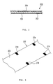
- FIG. 1 schematically shows the internal structure of a thermal printer 201.
- This thermal printer 201 can simultaneously print data on both sides of a double-sided thermal paper 202.
- the printer 201 can be used in, for example, cash registers for use in retail shops.
- the double-sided thermal paper 202 (hereinafter called "thermal paper") has a base paper 203 and two thermosensible layers 204 and 205.
- the layers 204 and 205 are formed on the obverse and reverse sides of the base paper 203, respectively. More precisely, the first thermosensible layer 204 is formed on one side (e.g., obverse side) of the base paper 203, and the second thermosensible layer 205 is formed on other side (e.g., reverse side) of the base paper 203.
- These layers 204 and 205 are made of material that attains a desired color, such as black or red, when it is heated to a temperature equal to or higher than a predetermined value.
- the thermal paper 202 is rolled, forming a roll, with the first thermosensible layer 204 turned inwards.
- the thermal printer 201 has a printer main unit 211 and a cover 212.
- the cover 121 can be opened and closed.
- the printer main unit 211 has a paper receptacle 213, in which the rolled thermal paper 202 is placed.
- the cover 212 can be rotated up and down, around the shaft 215 of a hinge unit 214 provided on the printer main unit 211. When the cover 212 opened, the printer main unit 211 is opened at the top.
- FIG. 1 shows the cover 212 in the closed state.
- a first thermal head 221 is provided in the printer main unit 211.
- the first thermal head 221 is arranged in the printer main unit 211 an can contact one side of the thermal paper 202, more precisely the first thermosensible layer 204.
- the first thermal head 221 is secured to a heat sink 222 that is a heat-radiating member.
- the first thermal head 221 and the heat sink 222 can rotate around a shaft 223.
- a first platen roller 231 is arranged and opposed to the first thermal head 221.
- the first platen roller 231 faces the first thermal head 221, clamping the thermal paper 202 jointly with the first thermal head 221, while the cover 212 remains closed as shown in FIG. 1 .
- the first platen roller 231 is made of elastic material having a coefficient of friction greater than that of metal, such as nitrilebutadiene rubber (NBR).
- the first platen roller 231 is shaped like a circular column and can rotate together with a first platen shaft 232 that extend in horizontal direction.
- a cutter mechanism 233 is located downstream with respect to the first thermal head 221 in the direction of feeding the thermal paper.
- the cutter mechanism 233 is used to cut the thermal paper 202.
- the cutter mechanism 233 is provided in, for example, the cover 212.
- the first thermal head 221 is set in a horizontal position, below the first platen roller 231.
- the distal-end part of the thermal paper 202 rolled and contained in the paper receptacle 213 passes through the nip between the first thermal head 221 and the first platen roller 231 and then through the cutter mechanism 233 and is ejected in the direction of arrow C shown in FIG. 1 .
- a first biasing means 234 is provided at the back of the first thermal head 221.
- An example of the first biasing means 234 is a spring member such as a compression spring or a torsion spring.
- the first biasing means 234 is arranged between the heat sink 222 and a spring seat 235 that is provided in the printer main unit 211.
- the first biasing means 234 pushes the first thermal head 221 toward the first platen roller 231 in the direction of arrow A shown in FIG. 1 .
- a first platen gear 241 is mounted on the first platen shaft 232.
- the first platen gear 241 rotates together with the first platen roller 231.
- the first platen shaft 232 is supported by a bearing (not shown) provided in the cover 212 and can rotate.
- a second thermal head 242 is provided in the cover 212.
- the second thermal head 242 is arranged upstream with respect to the first thermal head 221, in the direction of feeding the thermal paper 202.
- the second thermal head 242 is arranged in the cover 212 to contact the other side of the thermal paper 202, i.e., the second thermosensible layer 205.
- the second thermal head 242 is secured to a heat sink 243 that is a heat-radiating member.
- the second thermal head 242 can rotate around a shaft 244.
- a second platen roller 251 is provided in the printer main unit 211 and is opposed to the second thermal head 242.
- the second platen roller 251 faces the second thermal head 242, clamping the thermal paper 202 jointly with the second thermal head 242, while the cover 212 remains closed as is illustrated in FIG. 1 .
- the second thermal head 242 is arranged above the second platen roller 251 and inclined downward.
- the distal end part of the thermal paper 202 which is rolled and contained in the paper receptacle 213, passes through the nip between the second thermal head 242 and the second platen roller 251 and is fed toward the first thermal head 221.
- the second platen roller 251 is made of elastic material having a coefficient of friction greater than that of metal, such as NBR.
- the second platen roller 251 is shaped like a circular column and is mounted on a second platen shaft 252 that extend in horizontal direction.
- a second platen gear 253 is mounted on the second platen shaft 252.
- the second platen gear 253 rotates together with the second platen roller 251.
- the second platen shaft 252 is supported by a pair of bearings (not shown), i.e., left and right bearings provided in the printer main unit 211. The second platen shaft 252 can therefore rotate.
- a second biasing means 254 is provided at the back of the second thermal head 242.
- An example of the second biasing means 254 is a spring member such as a compression spring or a torsion spring.
- the second biasing means 254 is arranged between the heat sink 243 and a spring seat 255 that is provided in the cover 212.
- the second biasing means 254 pushes the second thermal head 242 toward the second platen roller 251 in the direction of arrow B shown in FIG. 1 .
- the printer main unit 211 incorporates a motor 261.
- An example of the motor 261 is a pulse motor that can rotate in both the forward direction and reverse direction. The angle through which it rotates (i.e., rotation angle) can be accurately controlled in accordance with the number of pulses output from a controller 272, which will be described later.
- An output gear 263 is mounted on the shaft 262 of the motor 261.
- the rotation of the shaft 262 of the motor 261 (hence, the rotation of the output gear 263) is transmitted via a drive-force transmitting mechanism 264 to the first platen roller 231 and the second platen roller 251.
- the drive-force transmitting mechanism 264 includes a reduction gear 265, a drive gear 266, the above-mentioned second platen gear 253, a pair of idler gears 267 and 268, and the above-mentioned first platen gear 241.
- the reduction gear 265 is set in mesh with the output gear 263.
- the drive gear 266 rotates together with the reduction gear 265.
- the second platen gear 253 is set in mesh with the drive gear 266.
- the first platen gear 241 is set in mesh with the idler gear 267.
- One idler gear 267 is arranged in the cover 212, and the other idler gear 268 is arranged in the printer main unit 211.
- the idler gears 267 and 268 mesh with each other as long as the cover 212 remains closed. When the cover 212 is opened, the idler gears 267 and 268 are disengaged from each other.
- One idler gears 267 meshes with the first platen gear 241 at all times.
- the other gear 268 meshes with the second platen gear 253 at all times.
- a first paper sensor 271 is arranged upstream with respect to the second thermal head 242, in the direction of feeding the thermal paper 202, in order to detect the thermal paper 202.
- the first paper sensor 271 is electrically connected to the controller 272.
- the controller 272 is an example of a control unit that uses a microprocessor or the like.
- the sensing unit 271a of the first paper sensor 271 may contact the thermal paper 202 from below. In this case, the first paper sensor 271 detects the thermal paper 202. When the first paper sensor 271 detects the thermal paper 202, it outputs a signal indicating that the thermal paper 202 has been detected. The signal is supplied to the controller 272.
- a second paper sensor 273 is arranged between the first thermal head 221 and the second thermal head 242.
- the second paper sensor 273 is a reflection-type sensor that can optically detect the distal end of the thermal paper 202 and comprises a light-emitting element and a light-receiving element.
- the second paper sensor 273 can detect timing marks 274 (see FIG. 3 ) that are printed on the thermal paper 202.
- the second paper sensor 273 detects the distal end of the thermal paper 202, it generates a signal indicating that the distal end has been detected. This signal is supplied to the controller 272.
- the timing marks 274 are marks that can be optically read.
- An example of a timing mark 274 is a black mark (e.g., black dot) that indicates the position where the thermal paper 202 should be cut.
- the thermal paper 202 is a double-sided thermal paper and has two thermosensible layers 204 and 205 on the obverse and reverse sides, respectively. Therefore, the first thermal head 221 can print the timing marks 274 on the first thermosensible layer 204, or the second thermal head 242 can print the marks 274 on the second thermosensible layer 205. To enable the second paper sensor 273 to detect the timing marks 274, however, the second thermal head 242 prints the timing marks 274. This is because the second thermal head 242 is arranged upstream with respect to the sensor 273 in the direction of feeding the thermal paper 202.
- the thermal paper 202 may be replaced by a single-sided thermal paper having only one thermosensible layer. If this is the case, the timing marks 274 are printed on the reverse side of the thermal paper (i.e., the side on which no thermosensible layers are provided). That is, the second paper sensor 273 of this embodiment can detect the timing marks 274 printed on the double-sided thermal paper 202 and the timing marks printed on a single-sided thermal paper.
- the controller 272 To control the position where to cut the thermal paper 202, by using the timing marks 274, the controller 272 outputs pulses to the motor 261 when the timing marks 274, in number that corresponds to the distance for which the paper 202 has been fed. On the bases of the number of pulses received, the motor 261 is driven by a prescribed angle. That part of the thermal paper 202, which is to be cut, therefore reaches the cutter mechanism 233.
- the cover 212 When the cover 212 is opened to replenish the thermal paper 202, the first platen roller 231 moves away from the first thermal head 221. At the same time, the second thermal head 242 moves away from the second platen roller 251. Further, the one idler gear 267 is disengaged from the other idler gear 268. The top of the printer main unit 211 is therefore opened. As a result, the first thermal head 221 and the second platen roller 251 are fully exposed to the outside.
- the first biasing means 234 keeps pushing the first thermal head 221 toward the first platen roller 231
- the second biasing means 254 keeps pushing the second thermal head 243 toward the second platen roller 251.
- the idler gears 267 and 268 come into mesh with each other.
- the thermal paper 202 is set in the paper receptacle 213, and the distal end of the paper 202 is led to the second thermal head 242. Then, the first paper sensor 271 detects the thermal paper 202, and the controller 272 outputs pulses. These pulses drive the motor 261 by the prescribed angle in the direction of arrow R shown in FIG. 1 . The second platen roller 251 is thereby rotated in the direction of arrow R2. The thermal paper 202 is therefore fed toward the first thermal head 221.
- the rotation of the shaft 262 of the motor 261 is transmitted via the drive-force transmitting mechanism 264 to the first platen roller 231 and the second platen roller 251.
- the first platen roller 231 and the second platen roller 251 therefore rotate in the direction of arrow R1 and the direction of arrow R2, respectively.
- the second paper sensor 273 detects the thermal paper 202.
- the controller 272 When the second paper sensor 273 detects the distal end of the thermal paper 202, the controller 272 outputs pulses. The pulses drive the motor 261 further, by the prescribed angle. Then, the thermal paper 202 is stopped at a preset printing position, with its distal end clamped between the first thermal head 221 and the first platen roller 231.
- the controller 272 When the controller 272 outputs a signal to the motor 261, instructing that data be printed, the motor 261 rotates the first platen roller 231 and the second platen roller 251 in the directions of arrows R1 and R2, respectively. At this time, the first thermal head 221 prints data on the first thermosensible layer 204 of the thermal paper 202. At the same time, the second thermal head 242 can print data on the second thermosensible layer 205 of the thermal paper 202. If necessary, the second thermal head 242 can print, on the desired parts of the second thermosensible layer 205, timing marks 274 that indicate the position where the paper 202 should be cut.
- the thermal paper 202 is fed toward the cutter mechanism 233. While the thermal paper 202 is being fed so, the second paper sensor 273 detects the timing marks 274. Thereafter, the paper 202 is further fed in accordance with the number of pulses output from controller 272, until that part of the thermal paper 202, at which the paper 202 is to be cut, reaches the cutter mechanism 233. Then, the cutter mechanism 233 operates, cutting the thermal paper 202.
- the thermal printer 201 has a paper-reversing function of driving the motor 261 in the reverse direction in order to move the distal end of the thermal paper 202 cut by the cutter mechanism 233, back to a position near the first thermal head 221. Since the paper-reversing function can return the distal end of the paper 202 to a position near the first thermal head 221, the paper 202 can be prevented from having an unprintable region, i.e., blank region. Thus, the thermal paper 202 will not be wasted.
- the thermal paper 202 can be cut, without using timing marks 274. If no timing marks 274 are used, the pulses output from the controller 272 drive the motor 261 by the prescribed angle, thereby feeding the paper 202 until the part of the paper 202, which is to be cut, reaches the cutter mechanism 233. Then, the cutter mechanism 233 operates, cutting the thermal paper 202.
- Timing marks may be already printed on the reverse side of a single-sided thermal paper (i.e., the side on which no thermosensible layers are provided).
- the position at which to cut the paper can be designated if the second paper sensor 273 detects the timing marks printed on the single-sided thermal paper.
- the thermal printer 201 according to this embodiment can use not only double-sided thermal papers, but also single-sided thermal papers.
- the components of the invention such as the first and second thermal heads, first and second platen rollers, cutter mechanism, drive-force transmitting mechanism, first paper sensor and second paper sensor, can of course be modified as needed.
- the marks printed on the thermal paper are not limited to timing marks. Any other optically readable marks may be printed, instead.
Landscapes
- Electronic Switches (AREA)
- Accessory Devices And Overall Control Thereof (AREA)
- Printers Characterized By Their Purpose (AREA)
- Handling Of Sheets (AREA)
- Particle Formation And Scattering Control In Inkjet Printers (AREA)
- Massaging Devices (AREA)
Claims (4)
- Drucker, umfassend
ein Thermopapier (202) mit einer thermosensitiven Schicht (204) auf mindestens einer Seite,
einen ersten Thermokopf (221), der so angeordnet ist, um die eine Seite des Thermopapiers (202) zu kontaktieren und die eine Seite des Thermopapiers (202) zu bedrucken;
eine erste Walze (321), die gegenüber dem ersten Thermokopf (221) über dem Thermopapier (202) angeordnet ist;
einen zweiten Thermokopf (242) zum Kontaktieren der zweiten Seite des Thermopapiers (202), der in Bezug auf den ersten Thermokopf (221) in Richtung der Aufgabe des Thermopapiers (202) stromaufwärts angeordnet ist;
eine zweite Walze (251), die gegenüber dem zweiten Thermokopf (242) und über dem Thermopapier (202) angeordnet ist;
einen ersten Papiersensor (271), der in Bezug auf den zweiten Thermokopf (242) in Richtung der Aufgabe des Thermopapiers (202) stromaufwärts angeordnet und dazu ausgebildet ist, das Thermopapier zu erfassen;
gekennzeichnet durch
einen Schneidmechanismus (233), der in Bezug auf den ersten Thermokopf (221) in Richtung der Aufgabe des Thermopapiers (202) stromabwärts angeordnet und dazu ausgebildet ist, das Thermopapier zu schneiden;
einen Motor (261);
einen Antriebskraft-Übertragungsmechanismus, der dazu ausgebildet ist, eine Rotation des Motors (261) auf die erste Walze (231) und die zweite Walze (251) zu übertragen;
einen zweiten Papiersensor (273), der zwischen dem ersten Thermokopf (221) und dem zweiten Thermokopf (242) angeordnet und dazu ausgebildet ist, das distale Ende des Thermopapiers (202) zu erfassen und auf optische Weise Markierungen zu lesen, die auf das Thermopapier (202) gedruckt sind, wobei die Markierungen Taktungsmarkierungen (274) sind, die eine Position anzeigen, wo das Thermopapier (202) zu schneiden ist, und der Motor (261) eine rückwärts gerichtete Funktion aufweist, um das distale Ende des Thermopapiers (202), welches mittels des Schneidmechanismus (233) geschnitten wurde, wieder zurück zu einer Position in, der Nähe des ersten Thermokopfs (221) zu bewegen. - Drucker nach Anspruch 1, wobei der zweite Papiersensor (273) ein Sensor des Reflexionstyps ist, der in der Lage ist, die Taktungsmarkierungen (274) auf optische Weise zu erfassen.
- Drucker nach Anspruch 2, wobei das Thermopapier (202) ein doppelseitiges Thermopapier ist, das thermosensitive Schichten (204, 205) auf beiden Seiten aufweist und der zweite Papiersensor (273) so ausgebildet ist, die Taktungsmarkierungen (274) zu erfassen, die der zweite Thermokopf (242) auf die andere Seite des Thermopapiers (202) gedruckt hat.
- Drucker nach Anspruch 2, wobei das Thermopapier (202) ein einseitiges Thermopapier ist, das nur auf einer Seite eine thermosensitive Schicht aufweist und der zweite Papiersensor (273) so ausgebildet ist, Taktungsmarkierungen (274) zu erfassen, die bereits auf die andere Seite des einseitigen Thermopapiers gedruckt sind.
Applications Claiming Priority (7)
| Application Number | Priority Date | Filing Date | Title |
|---|---|---|---|
| JP2006178946 | 2006-06-29 | ||
| JP2006178945A JP2008006673A (ja) | 2006-06-29 | 2006-06-29 | サーマルプリンタ |
| JP2006178951A JP2008006678A (ja) | 2006-06-29 | 2006-06-29 | 両面印刷サーマルプリンタ |
| JP2006178956 | 2006-06-29 | ||
| JP2007016592A JP2008030437A (ja) | 2006-06-29 | 2007-01-26 | プリンタ |
| JP2007016593A JP4177872B2 (ja) | 2006-06-29 | 2007-01-26 | 印刷装置 |
| EP07109059A EP1872957B1 (de) | 2006-06-29 | 2007-05-29 | Drucker |
Related Parent Applications (3)
| Application Number | Title | Priority Date | Filing Date |
|---|---|---|---|
| EP07109059.1 Division | 2007-05-29 | ||
| EP07109059A Division EP1872957B1 (de) | 2006-06-29 | 2007-05-29 | Drucker |
| EP07109059 Previously-Filed-Application | 2007-05-29 |
Publications (2)
| Publication Number | Publication Date |
|---|---|
| EP2085229A1 EP2085229A1 (de) | 2009-08-05 |
| EP2085229B1 true EP2085229B1 (de) | 2012-04-04 |
Family
ID=38535416
Family Applications (3)
| Application Number | Title | Priority Date | Filing Date |
|---|---|---|---|
| EP09159315A Active EP2085229B1 (de) | 2006-06-29 | 2007-05-29 | Drucker |
| EP07109059A Active EP1872957B1 (de) | 2006-06-29 | 2007-05-29 | Drucker |
| EP09159318A Active EP2085230B1 (de) | 2006-06-29 | 2007-05-29 | Drucker |
Family Applications After (2)
| Application Number | Title | Priority Date | Filing Date |
|---|---|---|---|
| EP07109059A Active EP1872957B1 (de) | 2006-06-29 | 2007-05-29 | Drucker |
| EP09159318A Active EP2085230B1 (de) | 2006-06-29 | 2007-05-29 | Drucker |
Country Status (4)
| Country | Link |
|---|---|
| EP (3) | EP2085229B1 (de) |
| CN (3) | CN101633274B (de) |
| AT (2) | ATE507082T1 (de) |
| DE (2) | DE602007014250D1 (de) |
Families Citing this family (11)
| Publication number | Priority date | Publication date | Assignee | Title |
|---|---|---|---|---|
| JP2011201017A (ja) * | 2010-03-24 | 2011-10-13 | Seiko Epson Corp | プリンター |
| CN101830125A (zh) * | 2010-06-11 | 2010-09-15 | 山东新北洋信息技术股份有限公司 | 双面打印机及其控制方法 |
| CN102463746B (zh) * | 2010-11-19 | 2014-04-02 | 山东新北洋信息技术股份有限公司 | 打印头组件及使用该组件的打印机 |
| JP5828583B2 (ja) * | 2011-03-29 | 2015-12-09 | 株式会社ミヤコシ | 両面印刷装置 |
| JP6118153B2 (ja) * | 2013-03-26 | 2017-04-19 | サトーホールディングス株式会社 | プリンター |
| JP6287930B2 (ja) * | 2015-03-31 | 2018-03-07 | ブラザー工業株式会社 | 印刷装置 |
| EP3524435B1 (de) * | 2016-10-05 | 2021-09-15 | Sato Holdings Kabushiki Kaisha | Drucker |
| CN107749132B (zh) * | 2017-11-15 | 2023-05-12 | 湖南长城医疗科技有限公司 | 凭条出纸口防插卡机构 |
| CN110194000A (zh) * | 2019-04-26 | 2019-09-03 | 深圳市普实科技有限公司 | 一种挤压式打印机构及其打印机 |
| CN110271298B (zh) * | 2019-07-26 | 2021-05-04 | 广西叶道网络科技有限公司 | 一种节能环保的壁挂式热敏打印机 |
| CN218519413U (zh) * | 2022-11-02 | 2023-02-24 | 武汉精臣智慧标识科技有限公司 | 一种热敏标签打印机 |
Family Cites Families (12)
| Publication number | Priority date | Publication date | Assignee | Title |
|---|---|---|---|---|
| JPS60115467A (ja) * | 1983-11-29 | 1985-06-21 | Canon Inc | プラテンの製造方法 |
| FR2642004B1 (fr) * | 1988-12-30 | 1995-02-03 | Oce Graphics France | Imprimante thermique grande largeur |
| US5452959A (en) * | 1994-08-26 | 1995-09-26 | Ko-Pack Corporation | Apparatus for printing characters onto both surfaces of a sheet material |
| JP3545830B2 (ja) * | 1995-04-27 | 2004-07-21 | 東芝テック株式会社 | ラベルプリンタ |
| US5868069A (en) * | 1996-09-17 | 1999-02-09 | Escher-Grad Technologies Inc. | Method of generating proofs of print signatures |
| US6523927B2 (en) * | 1997-08-06 | 2003-02-25 | Seiko Epson Corporation | Method and apparatus for processing recording media having embedded information |
| JPH11286147A (ja) | 1998-04-02 | 1999-10-19 | Nec Yonezawa Ltd | 両面印刷機構 |
| CN2378193Y (zh) * | 1999-06-21 | 2000-05-17 | 威海北洋电气集团股份有限公司 | 一种便携热敏打印机 |
| JP3727211B2 (ja) * | 2000-01-28 | 2005-12-14 | 株式会社沖データ | プラテンおよび印字装置 |
| US6784906B2 (en) * | 2001-12-18 | 2004-08-31 | Ncr Corporation | Direct thermal printer |
| JP3687912B2 (ja) * | 2002-08-29 | 2005-08-24 | 東芝テック株式会社 | プリンタユニット |
| US7828490B2 (en) * | 2006-05-31 | 2010-11-09 | Toshiba Tec Kabushiki Kaisha | Printing apparatus including a cover holding a thermal head and a platen roller on a hinged frame |
-
2007
- 2007-05-29 DE DE602007014250T patent/DE602007014250D1/de active Active
- 2007-05-29 EP EP09159315A patent/EP2085229B1/de active Active
- 2007-05-29 AT AT09159318T patent/ATE507082T1/de not_active IP Right Cessation
- 2007-05-29 AT AT09159315T patent/ATE552119T1/de active
- 2007-05-29 EP EP07109059A patent/EP1872957B1/de active Active
- 2007-05-29 DE DE602007011158T patent/DE602007011158D1/de active Active
- 2007-05-29 EP EP09159318A patent/EP2085230B1/de active Active
- 2007-06-28 CN CN2009101589258A patent/CN101633274B/zh active Active
- 2007-06-28 CN CN2009101589243A patent/CN101648464B/zh active Active
- 2007-06-28 CN CN2007101275406A patent/CN101096155B/zh active Active
Also Published As
| Publication number | Publication date |
|---|---|
| DE602007011158D1 (de) | 2011-01-27 |
| EP2085229A1 (de) | 2009-08-05 |
| CN101648464B (zh) | 2011-09-21 |
| CN101648464A (zh) | 2010-02-17 |
| CN101633274A (zh) | 2010-01-27 |
| EP1872957A3 (de) | 2008-11-05 |
| ATE507082T1 (de) | 2011-05-15 |
| ATE552119T1 (de) | 2012-04-15 |
| CN101096155B (zh) | 2010-06-02 |
| CN101633274B (zh) | 2012-08-08 |
| EP1872957B1 (de) | 2010-12-15 |
| EP1872957A2 (de) | 2008-01-02 |
| CN101096155A (zh) | 2008-01-02 |
| DE602007014250D1 (de) | 2011-06-09 |
| EP2085230B1 (de) | 2011-04-27 |
| EP2085230A1 (de) | 2009-08-05 |
Similar Documents
| Publication | Publication Date | Title |
|---|---|---|
| EP2085229B1 (de) | Drucker | |
| US20090284576A1 (en) | Printer | |
| JP2002337410A (ja) | 熱転写ラインプリンタ | |
| EP2918418B1 (de) | Bilderzeugungsvorrichtung | |
| JP2870574B2 (ja) | 熱転写印刷装置 | |
| JP5404153B2 (ja) | 印刷装置 | |
| JP3640443B2 (ja) | ビデオプリンタの給紙装置 | |
| JP2006082425A (ja) | カラー感熱プリンタ、およびプリンタ | |
| JP5438706B2 (ja) | 画像形成装置及びヘッド離間制御方法 | |
| JP5962417B2 (ja) | 熱転写プリント装置 | |
| JP2964868B2 (ja) | 熱転写カードプリンタ | |
| US7483668B2 (en) | Method for achieving accurate page margins on a media and duplex imaging apparatus thereof | |
| JP3886462B2 (ja) | プリンタの搬送制御方式およびプリンタの搬送制御方法 | |
| US20070059085A1 (en) | Printer | |
| KR20050005793A (ko) | 용지 반송 기구 | |
| JPS6387268A (ja) | カラ−サ−マルプリンタ | |
| JP3993053B2 (ja) | 熱転写プリンタ | |
| JP2008006673A (ja) | サーマルプリンタ | |
| JP2006175818A (ja) | プリンタ | |
| JP3590697B2 (ja) | カラーサーマルプリンタ | |
| JP4929067B2 (ja) | 印刷装置 | |
| JPH04235064A (ja) | 熱転写カラープリンタ | |
| JPH0721353U (ja) | プリンタの用紙搬送機構 | |
| JP2008213180A (ja) | 搬送装置及び画像形成装置 | |
| JPS63130364A (ja) | サ−マルヘツド |
Legal Events
| Date | Code | Title | Description |
|---|---|---|---|
| PUAI | Public reference made under article 153(3) epc to a published international application that has entered the european phase |
Free format text: ORIGINAL CODE: 0009012 |
|
| 17P | Request for examination filed |
Effective date: 20090504 |
|
| AC | Divisional application: reference to earlier application |
Ref document number: 1872957 Country of ref document: EP Kind code of ref document: P |
|
| AK | Designated contracting states |
Kind code of ref document: A1 Designated state(s): AT BE BG CH CY CZ DE DK EE ES FI FR GB GR HU IE IS IT LI LT LU LV MC MT NL PL PT RO SE SI SK TR |
|
| 17Q | First examination report despatched |
Effective date: 20100126 |
|
| GRAP | Despatch of communication of intention to grant a patent |
Free format text: ORIGINAL CODE: EPIDOSNIGR1 |
|
| GRAS | Grant fee paid |
Free format text: ORIGINAL CODE: EPIDOSNIGR3 |
|
| GRAA | (expected) grant |
Free format text: ORIGINAL CODE: 0009210 |
|
| AC | Divisional application: reference to earlier application |
Ref document number: 1872957 Country of ref document: EP Kind code of ref document: P |
|
| AK | Designated contracting states |
Kind code of ref document: B1 Designated state(s): AT BE BG CH CY CZ DE DK EE ES FI FR GB GR HU IE IS IT LI LT LU LV MC MT NL PL PT RO SE SI SK TR |
|
| REG | Reference to a national code |
Ref country code: GB Ref legal event code: FG4D |
|
| REG | Reference to a national code |
Ref country code: CH Ref legal event code: EP |
|
| REG | Reference to a national code |
Ref country code: AT Ref legal event code: REF Ref document number: 552119 Country of ref document: AT Kind code of ref document: T Effective date: 20120415 |
|
| REG | Reference to a national code |
Ref country code: IE Ref legal event code: FG4D |
|
| REG | Reference to a national code |
Ref country code: DE Ref legal event code: R096 Ref document number: 602007021809 Country of ref document: DE Effective date: 20120606 |
|
| REG | Reference to a national code |
Ref country code: NL Ref legal event code: VDEP Effective date: 20120404 |
|
| REG | Reference to a national code |
Ref country code: AT Ref legal event code: MK05 Ref document number: 552119 Country of ref document: AT Kind code of ref document: T Effective date: 20120404 |
|
| LTIE | Lt: invalidation of european patent or patent extension |
Effective date: 20120404 |
|
| PG25 | Lapsed in a contracting state [announced via postgrant information from national office to epo] |
Ref country code: SI Free format text: LAPSE BECAUSE OF FAILURE TO SUBMIT A TRANSLATION OF THE DESCRIPTION OR TO PAY THE FEE WITHIN THE PRESCRIBED TIME-LIMIT Effective date: 20120404 Ref country code: CY Free format text: LAPSE BECAUSE OF FAILURE TO SUBMIT A TRANSLATION OF THE DESCRIPTION OR TO PAY THE FEE WITHIN THE PRESCRIBED TIME-LIMIT Effective date: 20120404 Ref country code: FI Free format text: LAPSE BECAUSE OF FAILURE TO SUBMIT A TRANSLATION OF THE DESCRIPTION OR TO PAY THE FEE WITHIN THE PRESCRIBED TIME-LIMIT Effective date: 20120404 Ref country code: SE Free format text: LAPSE BECAUSE OF FAILURE TO SUBMIT A TRANSLATION OF THE DESCRIPTION OR TO PAY THE FEE WITHIN THE PRESCRIBED TIME-LIMIT Effective date: 20120404 Ref country code: PL Free format text: LAPSE BECAUSE OF FAILURE TO SUBMIT A TRANSLATION OF THE DESCRIPTION OR TO PAY THE FEE WITHIN THE PRESCRIBED TIME-LIMIT Effective date: 20120404 Ref country code: LT Free format text: LAPSE BECAUSE OF FAILURE TO SUBMIT A TRANSLATION OF THE DESCRIPTION OR TO PAY THE FEE WITHIN THE PRESCRIBED TIME-LIMIT Effective date: 20120404 Ref country code: IS Free format text: LAPSE BECAUSE OF FAILURE TO SUBMIT A TRANSLATION OF THE DESCRIPTION OR TO PAY THE FEE WITHIN THE PRESCRIBED TIME-LIMIT Effective date: 20120804 |
|
| PG25 | Lapsed in a contracting state [announced via postgrant information from national office to epo] |
Ref country code: GR Free format text: LAPSE BECAUSE OF FAILURE TO SUBMIT A TRANSLATION OF THE DESCRIPTION OR TO PAY THE FEE WITHIN THE PRESCRIBED TIME-LIMIT Effective date: 20120705 Ref country code: LV Free format text: LAPSE BECAUSE OF FAILURE TO SUBMIT A TRANSLATION OF THE DESCRIPTION OR TO PAY THE FEE WITHIN THE PRESCRIBED TIME-LIMIT Effective date: 20120404 Ref country code: PT Free format text: LAPSE BECAUSE OF FAILURE TO SUBMIT A TRANSLATION OF THE DESCRIPTION OR TO PAY THE FEE WITHIN THE PRESCRIBED TIME-LIMIT Effective date: 20120806 |
|
| PG25 | Lapsed in a contracting state [announced via postgrant information from national office to epo] |
Ref country code: BE Free format text: LAPSE BECAUSE OF FAILURE TO SUBMIT A TRANSLATION OF THE DESCRIPTION OR TO PAY THE FEE WITHIN THE PRESCRIBED TIME-LIMIT Effective date: 20120404 Ref country code: MC Free format text: LAPSE BECAUSE OF NON-PAYMENT OF DUE FEES Effective date: 20120531 |
|
| REG | Reference to a national code |
Ref country code: CH Ref legal event code: PL |
|
| PG25 | Lapsed in a contracting state [announced via postgrant information from national office to epo] |
Ref country code: RO Free format text: LAPSE BECAUSE OF FAILURE TO SUBMIT A TRANSLATION OF THE DESCRIPTION OR TO PAY THE FEE WITHIN THE PRESCRIBED TIME-LIMIT Effective date: 20120404 Ref country code: LI Free format text: LAPSE BECAUSE OF NON-PAYMENT OF DUE FEES Effective date: 20120531 Ref country code: EE Free format text: LAPSE BECAUSE OF FAILURE TO SUBMIT A TRANSLATION OF THE DESCRIPTION OR TO PAY THE FEE WITHIN THE PRESCRIBED TIME-LIMIT Effective date: 20120404 Ref country code: AT Free format text: LAPSE BECAUSE OF FAILURE TO SUBMIT A TRANSLATION OF THE DESCRIPTION OR TO PAY THE FEE WITHIN THE PRESCRIBED TIME-LIMIT Effective date: 20120404 Ref country code: CZ Free format text: LAPSE BECAUSE OF FAILURE TO SUBMIT A TRANSLATION OF THE DESCRIPTION OR TO PAY THE FEE WITHIN THE PRESCRIBED TIME-LIMIT Effective date: 20120404 Ref country code: NL Free format text: LAPSE BECAUSE OF FAILURE TO SUBMIT A TRANSLATION OF THE DESCRIPTION OR TO PAY THE FEE WITHIN THE PRESCRIBED TIME-LIMIT Effective date: 20120404 Ref country code: CH Free format text: LAPSE BECAUSE OF NON-PAYMENT OF DUE FEES Effective date: 20120531 Ref country code: DK Free format text: LAPSE BECAUSE OF FAILURE TO SUBMIT A TRANSLATION OF THE DESCRIPTION OR TO PAY THE FEE WITHIN THE PRESCRIBED TIME-LIMIT Effective date: 20120404 Ref country code: SK Free format text: LAPSE BECAUSE OF FAILURE TO SUBMIT A TRANSLATION OF THE DESCRIPTION OR TO PAY THE FEE WITHIN THE PRESCRIBED TIME-LIMIT Effective date: 20120404 |
|
| PLBE | No opposition filed within time limit |
Free format text: ORIGINAL CODE: 0009261 |
|
| STAA | Information on the status of an ep patent application or granted ep patent |
Free format text: STATUS: NO OPPOSITION FILED WITHIN TIME LIMIT |
|
| REG | Reference to a national code |
Ref country code: IE Ref legal event code: MM4A |
|
| PG25 | Lapsed in a contracting state [announced via postgrant information from national office to epo] |
Ref country code: IT Free format text: LAPSE BECAUSE OF FAILURE TO SUBMIT A TRANSLATION OF THE DESCRIPTION OR TO PAY THE FEE WITHIN THE PRESCRIBED TIME-LIMIT Effective date: 20120404 |
|
| 26N | No opposition filed |
Effective date: 20130107 |
|
| PG25 | Lapsed in a contracting state [announced via postgrant information from national office to epo] |
Ref country code: IE Free format text: LAPSE BECAUSE OF NON-PAYMENT OF DUE FEES Effective date: 20120529 Ref country code: ES Free format text: LAPSE BECAUSE OF FAILURE TO SUBMIT A TRANSLATION OF THE DESCRIPTION OR TO PAY THE FEE WITHIN THE PRESCRIBED TIME-LIMIT Effective date: 20120715 |
|
| REG | Reference to a national code |
Ref country code: DE Ref legal event code: R097 Ref document number: 602007021809 Country of ref document: DE Effective date: 20130107 |
|
| PG25 | Lapsed in a contracting state [announced via postgrant information from national office to epo] |
Ref country code: BG Free format text: LAPSE BECAUSE OF FAILURE TO SUBMIT A TRANSLATION OF THE DESCRIPTION OR TO PAY THE FEE WITHIN THE PRESCRIBED TIME-LIMIT Effective date: 20120704 Ref country code: MT Free format text: LAPSE BECAUSE OF FAILURE TO SUBMIT A TRANSLATION OF THE DESCRIPTION OR TO PAY THE FEE WITHIN THE PRESCRIBED TIME-LIMIT Effective date: 20120404 |
|
| PG25 | Lapsed in a contracting state [announced via postgrant information from national office to epo] |
Ref country code: TR Free format text: LAPSE BECAUSE OF FAILURE TO SUBMIT A TRANSLATION OF THE DESCRIPTION OR TO PAY THE FEE WITHIN THE PRESCRIBED TIME-LIMIT Effective date: 20120404 |
|
| PG25 | Lapsed in a contracting state [announced via postgrant information from national office to epo] |
Ref country code: LU Free format text: LAPSE BECAUSE OF NON-PAYMENT OF DUE FEES Effective date: 20120529 |
|
| PG25 | Lapsed in a contracting state [announced via postgrant information from national office to epo] |
Ref country code: HU Free format text: LAPSE BECAUSE OF FAILURE TO SUBMIT A TRANSLATION OF THE DESCRIPTION OR TO PAY THE FEE WITHIN THE PRESCRIBED TIME-LIMIT Effective date: 20070529 |
|
| REG | Reference to a national code |
Ref country code: FR Ref legal event code: PLFP Year of fee payment: 10 |
|
| REG | Reference to a national code |
Ref country code: FR Ref legal event code: PLFP Year of fee payment: 11 |
|
| REG | Reference to a national code |
Ref country code: FR Ref legal event code: PLFP Year of fee payment: 12 |
|
| REG | Reference to a national code |
Ref country code: FR Ref legal event code: PLFP Year of fee payment: 17 |
|
| PGFP | Annual fee paid to national office [announced via postgrant information from national office to epo] |
Ref country code: DE Payment date: 20250402 Year of fee payment: 19 |
|
| PGFP | Annual fee paid to national office [announced via postgrant information from national office to epo] |
Ref country code: GB Payment date: 20250401 Year of fee payment: 19 |
|
| PGFP | Annual fee paid to national office [announced via postgrant information from national office to epo] |
Ref country code: FR Payment date: 20250401 Year of fee payment: 19 |