EP2085242A2 - Procédé de fabrication d'un film d'une clarté cristalline et/ou transparent pour l'application d'une image sur le film, et procédé pour rendre le film auto-adhésif - Google Patents
Procédé de fabrication d'un film d'une clarté cristalline et/ou transparent pour l'application d'une image sur le film, et procédé pour rendre le film auto-adhésif Download PDFInfo
- Publication number
- EP2085242A2 EP2085242A2 EP09151528A EP09151528A EP2085242A2 EP 2085242 A2 EP2085242 A2 EP 2085242A2 EP 09151528 A EP09151528 A EP 09151528A EP 09151528 A EP09151528 A EP 09151528A EP 2085242 A2 EP2085242 A2 EP 2085242A2
- Authority
- EP
- European Patent Office
- Prior art keywords
- carrier
- film
- clear
- crystal
- adhesive layer
- Prior art date
- Legal status (The legal status is an assumption and is not a legal conclusion. Google has not performed a legal analysis and makes no representation as to the accuracy of the status listed.)
- Withdrawn
Links
- 238000000034 method Methods 0.000 title claims abstract description 43
- 239000000853 adhesive Substances 0.000 title claims abstract description 29
- 238000004519 manufacturing process Methods 0.000 title claims abstract description 11
- 239000012790 adhesive layer Substances 0.000 claims abstract description 75
- 239000010410 layer Substances 0.000 claims description 57
- 239000000463 material Substances 0.000 claims description 28
- 239000003086 colorant Substances 0.000 claims description 9
- 239000002313 adhesive film Substances 0.000 claims description 6
- 238000005304 joining Methods 0.000 claims description 6
- 229920002994 synthetic fiber Polymers 0.000 claims description 6
- 239000007788 liquid Substances 0.000 claims description 5
- 239000002356 single layer Substances 0.000 claims description 4
- 238000000926 separation method Methods 0.000 claims description 3
- 239000011521 glass Substances 0.000 claims 1
- 239000000976 ink Substances 0.000 description 25
- 230000001070 adhesive effect Effects 0.000 description 18
- 229920001296 polysiloxane Polymers 0.000 description 13
- 239000011888 foil Substances 0.000 description 8
- 239000000969 carrier Substances 0.000 description 6
- 239000002904 solvent Substances 0.000 description 6
- 239000011248 coating agent Substances 0.000 description 5
- 238000000576 coating method Methods 0.000 description 5
- 238000001035 drying Methods 0.000 description 5
- 239000003292 glue Substances 0.000 description 5
- 239000004800 polyvinyl chloride Substances 0.000 description 5
- 239000000758 substrate Substances 0.000 description 5
- 230000000694 effects Effects 0.000 description 4
- 229920000915 polyvinyl chloride Polymers 0.000 description 4
- 239000011247 coating layer Substances 0.000 description 3
- XLYOFNOQVPJJNP-UHFFFAOYSA-N water Substances O XLYOFNOQVPJJNP-UHFFFAOYSA-N 0.000 description 3
- 239000004743 Polypropylene Substances 0.000 description 2
- 230000003993 interaction Effects 0.000 description 2
- 230000001788 irregular Effects 0.000 description 2
- 239000000049 pigment Substances 0.000 description 2
- -1 polypropylene Polymers 0.000 description 2
- 229920001155 polypropylene Polymers 0.000 description 2
- 229920002799 BoPET Polymers 0.000 description 1
- 206010067482 No adverse event Diseases 0.000 description 1
- XUIMIQQOPSSXEZ-UHFFFAOYSA-N Silicon Chemical compound [Si] XUIMIQQOPSSXEZ-UHFFFAOYSA-N 0.000 description 1
- 239000006096 absorbing agent Substances 0.000 description 1
- 230000000712 assembly Effects 0.000 description 1
- 238000000429 assembly Methods 0.000 description 1
- 238000003490 calendering Methods 0.000 description 1
- 238000006243 chemical reaction Methods 0.000 description 1
- 150000001875 compounds Chemical class 0.000 description 1
- 238000005034 decoration Methods 0.000 description 1
- 239000000428 dust Substances 0.000 description 1
- 238000005516 engineering process Methods 0.000 description 1
- 238000005562 fading Methods 0.000 description 1
- 239000000945 filler Substances 0.000 description 1
- 238000010438 heat treatment Methods 0.000 description 1
- 238000012986 modification Methods 0.000 description 1
- 230000004048 modification Effects 0.000 description 1
- 239000002365 multiple layer Substances 0.000 description 1
- 229920006255 plastic film Polymers 0.000 description 1
- 238000003825 pressing Methods 0.000 description 1
- 238000002203 pretreatment Methods 0.000 description 1
- 230000001681 protective effect Effects 0.000 description 1
- 239000011241 protective layer Substances 0.000 description 1
- 230000005855 radiation Effects 0.000 description 1
- 229910052710 silicon Inorganic materials 0.000 description 1
- 239000010703 silicon Substances 0.000 description 1
- 239000013464 silicone adhesive Substances 0.000 description 1
- 239000003381 stabilizer Substances 0.000 description 1
- 238000003860 storage Methods 0.000 description 1
- 239000000126 substance Substances 0.000 description 1
Images


Classifications
-
- B—PERFORMING OPERATIONS; TRANSPORTING
- B41—PRINTING; LINING MACHINES; TYPEWRITERS; STAMPS
- B41M—PRINTING, DUPLICATING, MARKING, OR COPYING PROCESSES; COLOUR PRINTING
- B41M3/00—Printing processes to produce particular kinds of printed work, e.g. patterns
- B41M3/008—Sequential or multiple printing, e.g. on previously printed background; Mirror printing; Recto-verso printing; using a combination of different printing techniques; Printing of patterns visible in reflection and by transparency; by superposing printed artifacts
-
- B—PERFORMING OPERATIONS; TRANSPORTING
- B41—PRINTING; LINING MACHINES; TYPEWRITERS; STAMPS
- B41M—PRINTING, DUPLICATING, MARKING, OR COPYING PROCESSES; COLOUR PRINTING
- B41M5/00—Duplicating or marking methods; Sheet materials for use therein
- B41M5/0041—Digital printing on surfaces other than ordinary paper
- B41M5/0047—Digital printing on surfaces other than ordinary paper by ink-jet printing
-
- B—PERFORMING OPERATIONS; TRANSPORTING
- B41—PRINTING; LINING MACHINES; TYPEWRITERS; STAMPS
- B41M—PRINTING, DUPLICATING, MARKING, OR COPYING PROCESSES; COLOUR PRINTING
- B41M5/00—Duplicating or marking methods; Sheet materials for use therein
- B41M5/0041—Digital printing on surfaces other than ordinary paper
- B41M5/0064—Digital printing on surfaces other than ordinary paper on plastics, horn, rubber, or other organic polymers
-
- B—PERFORMING OPERATIONS; TRANSPORTING
- B41—PRINTING; LINING MACHINES; TYPEWRITERS; STAMPS
- B41M—PRINTING, DUPLICATING, MARKING, OR COPYING PROCESSES; COLOUR PRINTING
- B41M7/00—After-treatment of prints, e.g. heating, irradiating, setting of the ink, protection of the printed stock
-
- C—CHEMISTRY; METALLURGY
- C09—DYES; PAINTS; POLISHES; NATURAL RESINS; ADHESIVES; COMPOSITIONS NOT OTHERWISE PROVIDED FOR; APPLICATIONS OF MATERIALS NOT OTHERWISE PROVIDED FOR
- C09J—ADHESIVES; NON-MECHANICAL ASPECTS OF ADHESIVE PROCESSES IN GENERAL; ADHESIVE PROCESSES NOT PROVIDED FOR ELSEWHERE; USE OF MATERIALS AS ADHESIVES
- C09J7/00—Adhesives in the form of films or foils
- C09J7/20—Adhesives in the form of films or foils characterised by their carriers
- C09J7/22—Plastics; Metallised plastics
-
- C—CHEMISTRY; METALLURGY
- C09—DYES; PAINTS; POLISHES; NATURAL RESINS; ADHESIVES; COMPOSITIONS NOT OTHERWISE PROVIDED FOR; APPLICATIONS OF MATERIALS NOT OTHERWISE PROVIDED FOR
- C09J—ADHESIVES; NON-MECHANICAL ASPECTS OF ADHESIVE PROCESSES IN GENERAL; ADHESIVE PROCESSES NOT PROVIDED FOR ELSEWHERE; USE OF MATERIALS AS ADHESIVES
- C09J7/00—Adhesives in the form of films or foils
- C09J7/30—Adhesives in the form of films or foils characterised by the adhesive composition
-
- G—PHYSICS
- G09—EDUCATION; CRYPTOGRAPHY; DISPLAY; ADVERTISING; SEALS
- G09F—DISPLAYING; ADVERTISING; SIGNS; LABELS OR NAME-PLATES; SEALS
- G09F3/00—Labels, tag tickets, or similar identification or indication means; Seals; Postage or like stamps
- G09F3/08—Fastening or securing by means not forming part of the material of the label itself
- G09F3/10—Fastening or securing by means not forming part of the material of the label itself by an adhesive layer
-
- C—CHEMISTRY; METALLURGY
- C09—DYES; PAINTS; POLISHES; NATURAL RESINS; ADHESIVES; COMPOSITIONS NOT OTHERWISE PROVIDED FOR; APPLICATIONS OF MATERIALS NOT OTHERWISE PROVIDED FOR
- C09J—ADHESIVES; NON-MECHANICAL ASPECTS OF ADHESIVE PROCESSES IN GENERAL; ADHESIVE PROCESSES NOT PROVIDED FOR ELSEWHERE; USE OF MATERIALS AS ADHESIVES
- C09J2203/00—Applications of adhesives in processes or use of adhesives in the form of films or foils
- C09J2203/306—Applications of adhesives in processes or use of adhesives in the form of films or foils for protecting painted surfaces, e.g. of cars
Definitions
- the present invention relates to a method for producing a crystal-clear or transparent film, provided with or which can be provided with at least an image and also be provided with an adhesive layer to make the entire assembly self-adhesive.
- the invention also relates to a crystal-clear or transparent self-adhesive film which is provided or can be provided on one side with at least an image.
- a white carrier such as a sheet of paper
- an adhesive layer while the other side is provided with a printing layer.
- An image is formed on or in this printable layer with an inkjet printer.
- the self-adhesive carrier thus obtained can then be applied to a substrate or surface, i.e. the carrier can adhere thereto.
- Figure 1 shows a schematic cross-section of a carrier which is applied to a substrate
- Figure 2 shows a schematic cross-section of the manufacturing process of an underlying carrier.
- the figures show a carrier 1, a possible printing layer 2 with an image 7, an adhesive layer 3 and a substrate 4, onto which the carrier can be applied.
- a laminate layer 5 is applied with the aid of an adhesive layer 6.
- an assembly comprising two parts may be used, as is shown in Figure 2 .
- the first part comprises a carrier 1, a printing layer 2 and an adhesive layer 3, as well as a first silicone paper layer or film 9;
- the second part comprises a laminate layer 5, the adhesive layer 6 and a second silicone paper layer 8.
- the second silicone paper 8 is removed and the laminate layer 5 is applied to the printing layer 2 by means of the adhesive layer 6.
- the known method has the disadvantage that it is relatively laborious and that a relatively large amount of material is consumed (including the laminate layer 5, the adhesive layer 6 and the second silicone paper layer 8), thus making the costs of production relatively high.
- the carrier is first provided on one side with a special printing layer, into or onto which an image is applied, and an adhesive layer is then applied to the printing layer to which an image is applied.
- the printing layer with the image is therefore positioned between the adhesive layer and the carrier.
- the carrier itself forms the outer surface of the entire assembly, thus serving as a means of protection for the image in or on the printing layer. Since the carrier itself protects the image, the aforementioned protective laminate layer is not required.
- the method comprises providing a crystal-clear or transparent carrier with a special printable layer, for example, a layer designed for water-borne inks. Only after this printable layer (in the aforementioned patent also called a printing layer) is applied can the printing of both the printing carrier and printing layer commence. Two separate layers, namely the crystal-clear or transparent carrier and printing layer, are required in order to apply the images. If one chooses to apply a coating directly to a carrier, one is obliged to select a carrier which provides sufficient stiffness to support this carrier as it passes through the coating line. Moreover, this carrier also needs to be sufficiently resistant to the higher temperatures required to enable the drying of the coating layer.
- the carrier that has such properties, such as a PET film is unsuitable for use on highly curved and/or uneven surfaces (such as on a vehicle).
- EP 1 193 049 A1 discloses a method for producing a multi-layer laminated object that is provided with images.
- the object comprises a first layer onto which an image is applied during the first step of the manufacturing process. Once the images are applied a layer of PVC is applied with the aid of an adhesive layer. In a last stage of the manufacturing process a flexible or rigid supporting element is attached to the PVC layer with the aid of a further layer of adhesive.
- This known method also requires the use of a relatively large amount of material.
- the object of the present invention is achieve an improved method and improved assembly with a crystal-clear or transparent film provided with an image.
- the image can now be directly applied onto the crystal-clear or transparent film instead of onto a specially provided second layer, for example, a printing layer, as is the case in NL 1010888 , the additional process of applying the coating layer is no longer required.
- the entire assembly of the first and second layers comprises a smaller number of layers, and in a specific embodiment only a single crystal-clear or transparent film, this reduces the risk of the film separating when it is applied to an irregular surface.
- such a film especially when it concerns a single (monolayer) film, is easier to remove than the usual multiple-layer assembly.
- the ink used in printing the film or foil may penetrate the film or foil, as was usually the case in certain known methods, and there is also the risk that the ink and adhesive interact in such a manner that this reduces the quality of the adhesive layer.
- the image may also become 'cloudy' in appearance as a result of the effect of the ink on the adhesive... The risk of such a "cloudy' appearance occurring can now be prevented or reduced by pouring ink directly onto the film and by applying the adhesive layer later.
- transparent used herein is intended to denote “at least partially transparent” and the term “crystal-clear” is intended to denote 'essentially fully transparent'.
- the image on the crystal-clear or transparent film is protected due to the fact that the side of the crystal-clear or transparent film onto which the image is applied, is provided with the second assembly with the self-adhesive side on the image.
- the entire assembly of the first and second assembly can then be transported. After transportation, one or more of the removable carriers can be removed again.
- the adhesive layer is transferred from the second carrier to the crystal-clear or transparent film. This makes the crystal-clear or transparent film self-adhesive so that it can be easily applied to an underlying surface.
- the image is now contained between the transparent film of assembly 1 and the adhesive layer of assembly 2.
- the method preferably comprises the creation of an image on the crystal-clear or transparent film by printing directly on the surface thereof.
- the method comprises guiding the film applied to the first carrier through a printing unit, specifically an inkjet printer, in order to apply the ink directly on or in the crystal-clear or transparent film.
- the crystal-clear or transparent foil or film is delivered on a carrier, in particular - but not limited to - a paper carrier, it is technically possible for the film to be fed automatically through such a printing unit so that the speed with which the image is applied is greatly increased.
- the film is fed through the inkjet printers.
- a disadvantage of the known method was that the film itself should have sufficient properties to also serve as a carrier. This restricted the options in relation to the choice of material of the film.
- inks are used which are water-borne.
- the water is used as a means of transporting the pigment. After printing, the water needs to evaporate, which means that this kind of print requires a specific drying time.
- solvents solvents
- Advantages of this type of ink in relation to the water-based inks is that they dry much faster and do not need any special additional coating, and are colourfast and weatherproof. Solvents can also be used that react to form a chemical compound with the film, thus increasing the durability of the image.
- the method comprises first allowing the ink applied to the crystal-clear or transparent film to dry, followed by the joining of the first and second carriers after drying.
- the second assembly which serves to protect the image on the crystal-clear or transparent film during storage and transport of the entire assembly, is preferably formed by backing paper which is siliconised on at least one side and more preferably on two sides.
- the second carrier can be formed substantially from a material which, on the one hand is suitable to hold the adhesive of the adhesive layer but which, on the other hand, binds the adhesive in such a (weak) manner that the adhesive can be transferred from the second carrier to the crystal-clear or transparent film.
- the carrier may be formed only in part from this material, instead of using the aforementioned material to form the entire carrier.
- the carrier may be provided on one or two sides with a coating which has such material properties and whereby the rest of the carrier may be formed from a different material.
- the properties of the coating rather than those of the carrier itself ensure that the adhesive layer does not remain too firmly attached.
- An example of such a coating layer is a layer of silicone. This is why, in a particular preferred embodiment, silicone paper is used, preferably siliconised paper provided on both sides with a layer of silicone. This ensures that the paper with a silicone adhesive - prior to its use in the method according to the invention - can be rolled up without the adhesive layer sticking to the back of the silicone paper.
- any suitable adhesive can be used for the adhesive layer, as long as it can be attached to the crystal-clear clear or transparent film, with the applied image.
- the adhesive layer is only slightly transparent or practically non-transparent and even more preferably, the adhesive layer is essentially white, so that the adhesive layer forms a uniform background for the image, which is particularly advantageous if the film is to be applied to a surface which has a variable appearance.
- the adhesive layer is coloured white because most printers are not capable of printing a white colour.
- the film can be made from an extensible material, so that it is easier to attach to an irregular surface.
- the extensibility is preferably between 50% and 250%, more specifically between 100% and 200%.
- the film is also preferably UV-resistant in order for the applied image to be protected from the effects of the sun.
- the crystal-clear or transparent film is formed from a single layer, so that it is easier to remove than existing film, which is usually multilayered (i.e. a film layer and a laminate layer), after being applied to a surface. Moreover, the risk of the film separating is greatly reduced, especially on surfaces that are difficult to adhere to, which makes the film easier to manipulate.
- the film is preferably made from a synthetic material, preferably a polyvinyl chloride (PVC).
- PVC polyvinyl chloride
- Other synthetic materials are also conceivable, such as polypropylene (poly propylene) (PP), etc.
- the synthetic material is preferably more or less elastic (with an elasticity between 50% and 250% and more preferably between 100 % and 200%).
- the provision of the first carrier with crystal-clear or transparent film comprises the application on the first carrier of liquid plastic (film) material, in particular the pouring of the material on the first carrier and allowing the material to harden on the first carrier.
- liquid plastic (film) material in particular the pouring of the material on the first carrier and allowing the material to harden on the first carrier.
- a crystal-clear or transparent film which is or can be provided on one side with at least one image is (to be) applied directly to the film and whereby an adhesive layer with a removable carrier is also provided on the same side, whereby the film, removable carrier and adhesive layer are formed in such a manner that the adhesive layer can be transferred from the removable carrier to the crystal-clear or transparent film when separated in order to provide a self-adhesive film.
- the film comprises a removable carrier on the side opposite to the image to be applied and the aforementioned second removable carrier on the side on which the image is to be applied. In this way, the film is protected on both sides and can be (further) transported with little risk of damage.
- the crystal-clear or transparent film is preferably formed directly on the first carrier without an adhesive layer, for example by pouring film material onto the carrier and allowing the material to harden.
- a system comprising two parts.
- Part one is a crystal-clear or transparent foil or film.
- This film and/or foil relates to a film that has been poured onto a carrier or a calendered [hot-pressed] foil that is printable.
- the printed image is applied as a negative image because the side opposite to the pouring side is the transparent side.
- the carrier is not yet removed because this is still required for the protection of the image and for the further processing of the entire assembly.
- Part two comprises a siliconised carrier with a silicone layer on both sides onto which a white or transparent layer of adhesive is applied. This carrier is therefore siliconised on both sides.
- the double-sided silicon carrier enables the white or transparent adhesive layer to be rolled up.
- the adhesive layer is preferably white as most print-plotters are not provided with a means to print white.
- the negative image or presentation printed and/or to be printed must be laminated with part two, i.e. with the siliconised carrier provided with a white or transparent adhesive layer.
- This white adhesive layer provides the transparent or crystal-clear film (part 1) with a white tint on the printing or images sides.
- a carrier can be provided with a transparent adhesive layer for printers that are capable of printing the colour white.
- Part two may serve two purposes, namely as a carrier for the printed layer and/or printing layer, and as a protective layer for the printed image. After joining together, the carrier of part one can then be detached. Part two preferably remains in place until the film with the image is applied to an underlying surface, thus achieving a saving on the amount of material, work and time required.
- FIG 3 shows a further preferred embodiment of a system 10 according to the present invention.
- the system 10 comprises a first assembly comprising a first carrier 12, which is usually formed from backing paper, onto which at least a partially crystal-clear and/or transparent film 13 is applied.
- the adhesion between carrier 12 and the transparent film is achieved by the fact that the transparent film (preferably PVC) is poured onto the carrier in liquid form and allowed to dry.
- the adhesive layer is therefore strong enough for the subsequent processing to be carried out.
- the liquid film material e.g. a PVC paste
- volatile substances are released from the material which results in a certain degree of micro-porosity. This micro-porosity ensures improved adhesion of the ink to the crystal-clear or transparent film 13. This generally results in the improved printability of the film.
- the drying of the film material can be achieved by heating the entire carrier assembly to which the liquid film material is applied, for example, in a curing oven.
- any particular known crystal-clear or transparent film may be applied, all of which lie within reach of those skilled in the art.
- the film is made from material with a characteristic thickness of between 60-70 micrometers, although other thicknesses are also conceivable.
- the film 13 is provided with an imprint or an image 16 on the side opposite the side attached to the first carrier 12.
- the image is usually applied to the film 13 as a negative image, as seen from the side onto which the image is applied so that the image is visible as positive when viewed through the film 13, after the film is attached to an underlying surface.
- the conversion and printing of the image in negative is easily achieved with known computer software used for editing and/or processing any of these images.
- the image is formed by guiding the entire assembly of carrier 12 and film 13 through an inkjet printer.
- the invention is not limited to certain types of ink or any number of colours or the application of only a single black ink or a single coloured ink, the invention is particularly well suited for producing colour images, such as photos prints and such.
- the basic colours used are yellow, magenta and cyan, possibly in combination with black ink.
- the application of a larger number of colours is also conceivable.
- the images composed by such inkjet printers consist of a large number of small points or 'dots' rendered in the basic colours, each individual colour being sprayed, generally in quick succession, from printing heads in the printer onto the film 13, for example, with a density of 1320 or 720 'dots per inch' (dpi). All of these dots define thereby not only the shape of the image but also form the colours of the image by using a combination or combinations of the four or more basic colours. In this way, any conceivable colour or combination of colours can be obtained, as well as a high degree of resolution in the image.
- the ink is first allowed to dry. Once the ink is sufficiently dry, an adhesive layer (usually by means of a laminator) is provided on the side on which the image 16 is applied.
- the choice of suitable adhesives and glues will be apparent to those skilled in the art.
- the adhesives or glues may, for example, be white or opaque, their composition being such that they can be transferred from one specific backing material, for example siliconised paper, to another carrier such as a crystal-clear or transparent film. Clear or transparent adhesives or glues may also be used and mixed with suitable quantities of white pigments or fillers.
- the glue or adhesive layer 14 is applied to the film 13 in the following manner.
- a layer of adhesive 14 is applied to a second carrier 15, for example, one made from siliconised paper.
- the second carrier 15 is a carrier which, on the one hand is suitable to hold the adhesive (the said adhesive layer 14) but which, on the other hand, binds the adhesive in such a (weak) manner that the adhesive of the second carrier 15 can be transferred to the film 13 when the second carrier 15 with the applied adhesive layer 14 is pressed against the film 13.
- the second carrier 15 is formed by siliconised paper comprising paper coated on both sides with a layer of silicone.
- FIG 3 shows the state in which the assembly comprising the second carrier 15 provided with the adhesive layer 14 is applied to the film 13, the film 13 which, in turn, is attached to the second carrier 12.
- the system 10 of the first and second assembly comprising the second carrier 15, an adhesive layer 14, film 13 and the first carrier 12 can be stored and transported.
- the film 13 and, in particular, the image 16 applied thereto is protected by the first carrier 12 and second carrier 15.
- the first carrier 12 is removed, in most cases usually just before the film 13 is applied to a surface or substrate 4.
- the separation of the first carrier 12 and film 13 can be carried out by hand, simply by detaching or removing the carrier from the film 13.
- the state in which the first carrier 12 is removed, is shown in figure 4 .
- the second carrier 15 is removed, also by removing it by hand.
- the adhesive layer 14 originally attached thereto which is also pressed against the foil 13 in its transport state, is transferred from the second carrier 15 to the film 13. This means that when the second carrier 15 is removed, the adhesive layer 14 remains in place on the image.
- the state in which both the first and second carrier are removed from the film is shown in Figure 5 .
- the film 13, which is provided on the inside with an image 16, as well as an adhesive layer 14, can be attached to the underlying surface 4 by pressing the film 13 with adhesive layer firmly against the surface, as is shown in Figure 6 .
- the second carrier 15 may also be removed first. After removal of the second carrier, the whole of the film 13, provided with an image 16 and the bonding or adhesive layer 14 is applied to the surface, as well as the first carrier 12 attached to the film. Only when the film has adhered to the underlying surface is the first carrier 12 removed, for example by separating this from the film.
- the disadvantage of this sequence of procedures is that when the film is attached to the underlying surface, the surface to which the film is to be applied is not visible or is at least barely visible.
- the method of the invention and the adhesive film thus obtained may for example, be used for all known applications of inkjet technologies, such as producing self-adhesive transparencies of photographs, drawings, graphic designs and the like, for example for use as a decoration, logo, lettering and/or for advertising purposes.
- the surface to which the films can be attached may vary from vehicles, such as company vehicles, racing cars, boats, walls, floors, windows, banners, panels and the like.
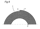
- Figures 7 and 8 show examples of how, in practice, the system of the first and second assembly can be delivered to a user.
- Figure 7 shows a roll (A) comprising the first assembly, for example, a rolled-up strip of the first backing material (12) to which a film (13) is attached.
- Figure 8 shows a roll (B) comprising the second assembly, for example, a rolled-up strip of the second backing material (15), which is provided on both sides with of a layer of silicone (18) and is provided on one side with a (preferably white) adhesive layer (14).
- the user will apply one or more images to the inside of the film (13), after which the first and second assembly can be joined together. This then enables the system of joined assemblies to be transported.
- the film is made self-adhesive in that position and can be attached to an underlying surface.
Landscapes
- Chemical & Material Sciences (AREA)
- Organic Chemistry (AREA)
- Physics & Mathematics (AREA)
- General Physics & Mathematics (AREA)
- Engineering & Computer Science (AREA)
- Theoretical Computer Science (AREA)
- Laminated Bodies (AREA)
- Ink Jet Recording Methods And Recording Media Thereof (AREA)
- Application Of Or Painting With Fluid Materials (AREA)
Applications Claiming Priority (1)
| Application Number | Priority Date | Filing Date | Title |
|---|---|---|---|
| NL2001229A NL2001229C2 (nl) | 2008-01-29 | 2008-01-29 | Werkwijze voor het vervaardigen van een glasheldere en/of transparante zelfklevende folie, bedoeld om te voorzien van een afbeelding, alsmede wekwijze om deze folie zelfklevend te maken. |
Publications (2)
| Publication Number | Publication Date |
|---|---|
| EP2085242A2 true EP2085242A2 (fr) | 2009-08-05 |
| EP2085242A3 EP2085242A3 (fr) | 2010-10-06 |
Family
ID=39759034
Family Applications (1)
| Application Number | Title | Priority Date | Filing Date |
|---|---|---|---|
| EP09151528A Withdrawn EP2085242A3 (fr) | 2008-01-29 | 2009-01-28 | Procédé de fabrication d'un film d'une clarté cristalline et/ou transparent pour l'application d'une image sur le film, et procédé pour rendre le film auto-adhésif |
Country Status (2)
| Country | Link |
|---|---|
| EP (1) | EP2085242A3 (fr) |
| NL (1) | NL2001229C2 (fr) |
Cited By (1)
| Publication number | Priority date | Publication date | Assignee | Title |
|---|---|---|---|---|
| WO2017111913A1 (fr) * | 2015-12-21 | 2017-06-29 | Hewlett-Packard Development Company, L.P. | Kit de support de film |
Citations (2)
| Publication number | Priority date | Publication date | Assignee | Title |
|---|---|---|---|---|
| NL1010888C2 (nl) | 1998-12-23 | 2000-06-26 | Herman Rudolf Bosman Sr | Werkwijze voor het vervaardigen van een transparante film met printlaag, voorzien voor een afbeelding, en middelen voor het gebruik om het zelfklevend te maken, bij deze werkwijze. |
| EP1193049A1 (fr) | 1998-11-11 | 2002-04-03 | De la Cruz Molina, Christina M. | Procede d'obtention d'un corps sur lequel sont imprimees des images et corps ainsi obtenu |
Family Cites Families (10)
| Publication number | Priority date | Publication date | Assignee | Title |
|---|---|---|---|---|
| FR1387518A (fr) * | 1963-02-26 | 1965-05-19 | ||
| US5266377A (en) * | 1989-03-17 | 1993-11-30 | Yoshino Kogyosho Co., Ltd. | Label and method for in-mold molding using a label thereof |
| US5798161A (en) * | 1995-01-20 | 1998-08-25 | Dai Nippon Printing Co., Ltd. | Optical disk, method of forming image on optical disk, image forming apparatus and adhesive layer transfer sheet |
| CN1489522A (zh) * | 2000-12-22 | 2004-04-14 | 艾弗里・丹尼森公司 | 顺从的薄膜和由其制得的制品 |
| JP2003177673A (ja) * | 2001-12-13 | 2003-06-27 | Toppan Label Co Ltd | リサイクル対応ラベル |
| US6788451B2 (en) * | 2002-09-11 | 2004-09-07 | Marcelo E. Mortarotti | Method for obtaining a printed product with visual effects, and printed product |
| DE10340245A1 (de) * | 2003-08-29 | 2005-03-24 | Dierk Spitzer | Verfahren zur Herstellung eines vorkonfektionierten Foliensatzes |
| US7691437B2 (en) * | 2003-10-31 | 2010-04-06 | 3M Innovative Properties Company | Method for preparing a pressure-sensitive adhesive |
| US8252409B2 (en) * | 2004-02-19 | 2012-08-28 | Hewlett-Packard Development Company, L.P. | Durable printed composite materials and associated methods |
| US20070252380A1 (en) * | 2006-02-07 | 2007-11-01 | Ward/Kraft | High gloss film based pressure sensitive prime label assembly having enhanced imaged resolution |
-
2008
- 2008-01-29 NL NL2001229A patent/NL2001229C2/nl not_active IP Right Cessation
-
2009
- 2009-01-28 EP EP09151528A patent/EP2085242A3/fr not_active Withdrawn
Patent Citations (2)
| Publication number | Priority date | Publication date | Assignee | Title |
|---|---|---|---|---|
| EP1193049A1 (fr) | 1998-11-11 | 2002-04-03 | De la Cruz Molina, Christina M. | Procede d'obtention d'un corps sur lequel sont imprimees des images et corps ainsi obtenu |
| NL1010888C2 (nl) | 1998-12-23 | 2000-06-26 | Herman Rudolf Bosman Sr | Werkwijze voor het vervaardigen van een transparante film met printlaag, voorzien voor een afbeelding, en middelen voor het gebruik om het zelfklevend te maken, bij deze werkwijze. |
Cited By (2)
| Publication number | Priority date | Publication date | Assignee | Title |
|---|---|---|---|---|
| WO2017111913A1 (fr) * | 2015-12-21 | 2017-06-29 | Hewlett-Packard Development Company, L.P. | Kit de support de film |
| US10696075B2 (en) | 2015-12-21 | 2020-06-30 | Hewlett-Packard Development Company, L.P. | Film media kit |
Also Published As
| Publication number | Publication date |
|---|---|
| NL2001229C2 (nl) | 2009-07-30 |
| EP2085242A3 (fr) | 2010-10-06 |
Similar Documents
| Publication | Publication Date | Title |
|---|---|---|
| CN101583497B (zh) | 喷墨打印用单向透视膜、打印膜以及它们的制作方法 | |
| US5851614A (en) | Self-adhesive opaque dry transfer decals | |
| CN101616807B (zh) | 对印刷叠加层的改进 | |
| US6979141B2 (en) | Identification cards, protective coatings, films, and methods for forming the same | |
| US12109828B2 (en) | Decorative floor covering production method | |
| US20080152809A1 (en) | Method and apparatus for making signs | |
| US5162141A (en) | Polymeric sheet having an incompatible ink permanently bonded thereto | |
| US6042914A (en) | Transferable medium for inkjet printing | |
| US20130287972A1 (en) | Hybrid heat transfer label | |
| US20040143914A1 (en) | Method and laminate for applying dye sublimated ink decoration to a surface | |
| CN105102220B (zh) | 用于层压在图像支持物上的具有金属消光饰面的可印刷薄膜和制造方法 | |
| CN209683229U (zh) | 一种数码可变热转印膜 | |
| EP0900149A1 (fr) | Decalcomanie | |
| SK2822002A3 (en) | Transfer label | |
| NL2001229C2 (nl) | Werkwijze voor het vervaardigen van een glasheldere en/of transparante zelfklevende folie, bedoeld om te voorzien van een afbeelding, alsmede wekwijze om deze folie zelfklevend te maken. | |
| JP2000351265A (ja) | アルミニウム転写蒸着記録用紙及びそれを用いたタック加工記録用紙 | |
| BE1012601A3 (nl) | Werkwijze voor het vervaardigen van een transparante film met printlaag, voorzien voor een afbeelding, en middelen voor het gebruik om het zelfklevend te maken, bij deze werkwijze. | |
| NL1010888C2 (nl) | Werkwijze voor het vervaardigen van een transparante film met printlaag, voorzien voor een afbeelding, en middelen voor het gebruik om het zelfklevend te maken, bij deze werkwijze. | |
| JP3122765U (ja) | 床用タイル | |
| RU2807955C1 (ru) | Способ получения декоративного напольного покрытия | |
| JP3801599B2 (ja) | 成形品製造方法およびそれに用いる転写シート | |
| EP1431060B1 (fr) | Utilisation d'une couche autocollante | |
| EP2364863A1 (fr) | Ensemble pour l'amélioration de la visibilité pendant l'obscurité et procédé de production dudit ensemble | |
| CN116137918A (zh) | 混合热转印标签组件 | |
| HK40117742A (en) | Method for manufacturing transfer foil by hybrid printing and transfer foil |
Legal Events
| Date | Code | Title | Description |
|---|---|---|---|
| PUAI | Public reference made under article 153(3) epc to a published international application that has entered the european phase |
Free format text: ORIGINAL CODE: 0009012 |
|
| AK | Designated contracting states |
Kind code of ref document: A2 Designated state(s): AT BE BG CH CY CZ DE DK EE ES FI FR GB GR HR HU IE IS IT LI LT LU LV MC MK MT NL NO PL PT RO SE SI SK TR |
|
| AX | Request for extension of the european patent |
Extension state: AL BA RS |
|
| PUAL | Search report despatched |
Free format text: ORIGINAL CODE: 0009013 |
|
| AK | Designated contracting states |
Kind code of ref document: A3 Designated state(s): AT BE BG CH CY CZ DE DK EE ES FI FR GB GR HR HU IE IS IT LI LT LU LV MC MK MT NL NO PL PT RO SE SI SK TR |
|
| AX | Request for extension of the european patent |
Extension state: AL BA RS |
|
| RIC1 | Information provided on ipc code assigned before grant |
Ipc: C09J 7/02 20060101ALI20100830BHEP Ipc: G09F 3/10 20060101ALI20100830BHEP Ipc: B41M 7/00 20060101ALI20100830BHEP Ipc: B41M 5/00 20060101ALI20100830BHEP Ipc: B41M 3/00 20060101AFI20090611BHEP |
|
| AKY | No designation fees paid | ||
| REG | Reference to a national code |
Ref country code: DE Ref legal event code: R108 Effective date: 20110526 |
|
| STAA | Information on the status of an ep patent application or granted ep patent |
Free format text: STATUS: THE APPLICATION IS DEEMED TO BE WITHDRAWN |
|
| 18D | Application deemed to be withdrawn |
Effective date: 20110407 |