EP2085505A2 - Peigne fixe destiné à une peigneuse - Google Patents
Peigne fixe destiné à une peigneuse Download PDFInfo
- Publication number
- EP2085505A2 EP2085505A2 EP08018741A EP08018741A EP2085505A2 EP 2085505 A2 EP2085505 A2 EP 2085505A2 EP 08018741 A EP08018741 A EP 08018741A EP 08018741 A EP08018741 A EP 08018741A EP 2085505 A2 EP2085505 A2 EP 2085505A2
- Authority
- EP
- European Patent Office
- Prior art keywords
- comb
- support plate
- stiffening element
- holding portion
- fixkammträgers
- Prior art date
- Legal status (The legal status is an assumption and is not a legal conclusion. Google has not performed a legal analysis and makes no representation as to the accuracy of the status listed.)
- Granted
Links
Images
Classifications
-
- D—TEXTILES; PAPER
- D01—NATURAL OR MAN-MADE THREADS OR FIBRES; SPINNING
- D01G—PRELIMINARY TREATMENT OF FIBRES, e.g. FOR SPINNING
- D01G19/00—Combing machines
- D01G19/06—Details
- D01G19/10—Construction, mounting, or operating features of combing elements
-
- D—TEXTILES; PAPER
- D01—NATURAL OR MAN-MADE THREADS OR FIBRES; SPINNING
- D01H—SPINNING OR TWISTING
- D01H5/00—Drafting machines or arrangements ; Threading of roving into drafting machine
- D01H5/02—Gill boxes or other drafting machines employing fallers or like pinned bars
- D01H5/12—Details
- D01H5/14—Pinned bars
Definitions
- the invention relates to a fixed comb of a combing machine with a Fixkammarme which has a holding portion which is connected to a support plate on which a pin strip, or a Fixkammgarnitur is attached.
- the comb of a combing machine is subjected to alternating dynamic loads during the combing process, which in part make themselves noticeable in an elastic deformation of the fixing comb, in particular in its longitudinal direction. This in turn affects the attachment points of the Fixkammes in the combing machine. This means that due to the elastic deflection of the fixing comb occurring transversely to its longitudinal direction, relative movements occur between the fixedly mounted holding elements (eg retaining clips) and the holding section of the fixing comb. As a result, the holding section is subject to wear in this area.
- the number of combing heads eight fixed combs are used on a combing machine.
- the minimum distance of the fixed comb to the tear-off rollers is to be selected larger by the amount of deflection in order to avoid a collision of the fixed comb during its combing position with the tear-off rollers.
- different combing conditions are obtained over the width of the nonwoven fabric to be stripped, since the deflection decreases in the direction of the outer ends of the fixed comb. from that results in that due to the deflection of the distance of the top comb to the tear-off rollers in the middle region is the lowest, while it increases in the direction of the outer ends. This can lead to different combing results over the length of the Fixkammes.
- the invention thus has the object to avoid the disadvantages mentioned and to propose an embodiment of a fixed comb with increased bending strength, whereby the relative movements between the holding portion of the Fixkammes and its fasteners are minimized. At the same time, care must be taken to ensure that the mass of the top comb is changed only slightly and that the narrow geometrical mounting mass of the top comb between the nipper unit and the puller rollers is taken into account.
- This object is achieved by proposing that at least one additional stiffening element is mounted on the carrier plate, which increases the bending stiffness of the fixed comb carrier in its longitudinal direction.
- the term "longitudinal direction" refers to the length of the fixed comb, which extends in the installation position in the combing machine transversely to the direction of flow of the fiber material.
- the proposed embodiment the mass of the fixed comb is increased slightly.
- the stiffening element can be mounted in the area in which it is not a hindrance despite the tight installation conditions.
- the stiffening element is therefore - seen in the installation position of the fixed comb - mounted on the side of the support plate, which faces the subsequent Abreisswalzen. This corresponds - seen in the flow direction of the fiber material - the front side of the support plate.
- the stiffening element - viewed in the longitudinal direction of the Fixkammippos - extending from the center of the Fixkammmiks in the direction of its two ends and has a distance from the ends of the Fixkammmiks. This makes it possible that in the respective remaining free area between the ends of the stiffening element and the respective end of the Fixkammembls holding elements for fixing the Fixkammes, as previously known, can be used.
- the stiffening element is connected to the holding section and the carrier plate. This results in a particularly stable and compact design, which also in addition a significant increase in the bending stiffness, is achieved transversely to the longitudinal direction of the Fixkammmiks. Moreover, this makes it possible to form the stiffening element with the holding portion and the support plate together as a hollow profile. This results in an execution of the Fixkammmiks in lightweight construction while increasing the flexural strength. As already described, an increase in the bending strength of the Fixkamm umans is achieved transversely to its longitudinal extent, which also has an advantageous effect on the constant maintenance of the position of the tips of the Fixkammgarnitur during the tearing or combing process. In order to adapt to the geometrical conditions in the area of the tear-off rollers, it is proposed that the hollow profile-seen in cross-section-has a cross-sectional area which decreases in the direction of the tips of the pin strip.
- the fixed comb carrier formed from the holding section, the carrier plate and the stiffening element is made in one piece.
- the proposal to produce the Fixkammou made of plastic results in a weight reduction and allows the increase in Kammspiellibrary with increased flexural strength. Due to the corresponding design of the stiffening element as a hollow profile, the production of the Fixkammparticularlys from an extruded profile also offers.
- the extruded profile may consist of a non-metallic material for weight reduction, z. B. of an aluminum alloy. It is further proposed an embodiment, wherein the specific gravity of the stiffening element is less than the specific weight of the holding portion and the support plate. This makes it possible to increase the bending stiffness of the Fixkammippos, the weight of the Fixkammwheres is only slightly increased. In particular, for the subsequent attachment of such stiffening elements already in use Fixkammmikn it is advantageous if they can be connected by means of adhesives with the support plate or with the support plate and the holding portion of the Fixkammetcs.
- the object of the invention is also achieved by an embodiment, wherein it is proposed that the support plate is provided with respect to its cross-sectional area over at least a portion of its longitudinal direction with a flexural rigidity of the support plate in its longitudinal direction increasing profiling. This means that the stiffening to increase the bending strength is integrated directly into the carrier plate. Further advantages of the invention are described in more detail in subsequent embodiments and shown.
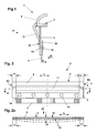
- Fig. 1 shows a cross section of an inventively designed Fixkammongs 2 a Fixkammes 1 with a combing machine, not shown.
- the Fixkammlust 2 is formed from a holding portion 4, to which a support plate 5 is attached.
- the holding section 4 has the cross-sectional shape of an open profile with an arcuate outer surface.
- the holding section 4 and the carrier plate 5 may be made of one piece (eg of plastic or of an extruded aluminum alloy).
- a stiffening element 11 is attached, which, as from FIG.
- the stiffening element 11 is connected to the holding section 2 at one end and to the carrier plate 5 at the other end. Together with the holding portion 4 and the support plate 5, the stiffening element 11 forms a hollow profile with a triangular cross-section.
- a Fixkammgarnitur 7 is attached via a plurality of screws 14 and a clamping plate 15. According to the number of screws 14 threaded holes 16 are mounted in the support plate 15. About the screws 14 and the clamping plate 15, the clothing 7 is clamped on the support plate 5.
- the clothing 7 of the fixed comb 1 can be made of strung pinstripes, of juxtaposed stamped or embossed sheets or in any other form. However, this is irrelevant to the presentation of the invention.
- FIG. 2a schematically shows how the deflection b of the support plate 5 of the Fixkammismes 2 by the resulting force F takes place in the flow direction D.
- the fiber tuft combed out by means of a circular comb is subsequently pulled in the flow direction D over the tear-off rollers through the clothing 7 of the fixing comb 1 during the tearing process.
- deflection b of the carrier plate 5 occurs, in particular in the middle region of the fixed comb 2. This is an elastic deflection which oscillates back after the force F has been eliminated. Ie. at a Kammspielteil of z. B. 500 KS / min, this process is 500 times per minute.
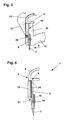
- FIG. 3 View Y
- the retaining clip 21 is formed at its free end so that it a latching position when reaching over the arcuate outer contour of the holding section 4 occupies.
- the function of this retaining clip is also from the embodiments of DE-102 52 098 A1 refer to.
- the dashed line 21 'in FIG. 3 shows the retaining clip 21 in its unlocked position, wherein the Fixkammisme 2 can be taken out of a slot 19 of a vertical receptacle 18 of the Fixkammhalters 17 upwards.
- two such Fixkammhalter 17 are attached to a nipper unit, not shown.
- the holding section 4 in the region of its fastenings 21 will be closed by the described relative movements.
- the deflection b is considerably reduced and thus reduced the risk of wear in the area of stops. By reducing the deflection to a minimum, it is also ensured that the geometrical combing conditions remain substantially constant over the entire length of the fixing comb 1.
- FIG. 4 a further embodiment is shown, wherein the Fixkammarme 2 also from a holding portion 4 and a support plate 5 attached thereto according to the embodiment according to FIG. 1 consists.
- the attachment of a Fixkammgarnitur 7 corresponds to the embodiment according to FIG. 1
- a stiffening element 12 is attached in the present example, which here, for example, has a rectangular cross-section. However, other cross-sectional shapes are conceivable.
- the stiffening element 12 is connected to the holding portion 4 and the support plate 5.
- the stiffening element 12 may be formed from a non-metallic material (eg plastic) so that the mass of the fixed comb to be moved is increased only insignificantly by the attachment of an additional stiffening element.
- a non-metallic material eg plastic
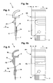
- Fig. 5 shows a further embodiment of the invention, wherein the support plate 5 itself with a profile P1 which extends in the longitudinal direction L of the Fixkammmiks 2, is provided.
- Fig. 5a shows a view Z of Fig. 5 , It can be seen that the profile P1 extends to a distance a to the edge R1 of the Fixkammparticularlys 2. On the opposite side, which is not shown, likewise the profile P1 ends at a distance a from the edge R2. As already in the embodiment of Fig. 2 described, this free space with the distance a for the mounting and attachment of the Fixkammenvirons 2 in Fixkammhaltern 17 ( Fig. 3 ) needed.
- the profile P1 can be produced by deep drawing, stamping or with other known production methods.
- the support plate 5 can be made with the profile P1 in one operation.
- the carrier plate 5 is connected to the holding section 4 via welding seams shown schematically. There are also other types of connection possible.
- the holding plate 4 and the support plate 5 may be made in one piece.
- Fig. 6 with the associated side view K shows a further embodiment, wherein a triangular profile P2 is integrated directly into the support plate 5a.
- the holding part 4a is fixedly connected to the support plate 5a. That means in the present example the Fig. 6 the support plate 5a with the profile P2 and the holding part 4a are made in one piece.
- the stiffening profile ends to increase the bending strength in each case at a distance a to the respective edge R1 and R2. If the Fixkammlust 2 of Fig. 6 is made of an extruded profile, it is possible to obtain the free space at a distance a, by appropriate processing to remove the profile P2 in this space a.
Landscapes
- Engineering & Computer Science (AREA)
- Textile Engineering (AREA)
- Mechanical Engineering (AREA)
- Preliminary Treatment Of Fibers (AREA)
Applications Claiming Priority (1)
| Application Number | Priority Date | Filing Date | Title |
|---|---|---|---|
| CH1252008 | 2008-01-29 |
Publications (3)
| Publication Number | Publication Date |
|---|---|
| EP2085505A2 true EP2085505A2 (fr) | 2009-08-05 |
| EP2085505A3 EP2085505A3 (fr) | 2011-05-18 |
| EP2085505B1 EP2085505B1 (fr) | 2012-05-16 |
Family
ID=40361517
Family Applications (1)
| Application Number | Title | Priority Date | Filing Date |
|---|---|---|---|
| EP20080018741 Active EP2085505B1 (fr) | 2008-01-29 | 2008-10-27 | Peigne fixe destiné à une peigneuse |
Country Status (2)
| Country | Link |
|---|---|
| EP (1) | EP2085505B1 (fr) |
| CN (1) | CN101498066B (fr) |
Cited By (7)
| Publication number | Priority date | Publication date | Assignee | Title |
|---|---|---|---|---|
| CN103436998A (zh) * | 2013-07-23 | 2013-12-11 | 经纬纺织机械股份有限公司 | 精梳机顶梳弹簧压板装置 |
| EP2924152A2 (fr) | 2014-03-24 | 2015-09-30 | Kabushiki Kaisha Toyota Jidoshokki | Dispositif de peigne supérieur d'une peigneuse |
| EP2924153A2 (fr) | 2014-03-24 | 2015-09-30 | Kabushiki Kaisha Toyota Jidoshokki | Dispositif de peigne supérieur d'une peigneuse |
| WO2015154841A1 (fr) * | 2014-04-11 | 2015-10-15 | TRüTZSCHLER GMBH & CO. KG | Peigne fixe pour peigneuse |
| WO2015154840A1 (fr) * | 2014-04-11 | 2015-10-15 | TRüTZSCHLER GMBH & CO. KG | Peigne fixe de peigneuse |
| JP2015533951A (ja) * | 2012-09-28 | 2015-11-26 | マシーネンファブリク リーター アクチェンゲゼルシャフトMaschinenfabrik Rieter AG | トップコーム取付け部材 |
| EP4060102A1 (fr) * | 2021-03-19 | 2022-09-21 | Maschinenfabrik Rieter AG | Support pour un peigne de fixation d'une machine à peigner |
Families Citing this family (1)
| Publication number | Priority date | Publication date | Assignee | Title |
|---|---|---|---|---|
| CN105442108B (zh) * | 2015-12-24 | 2020-06-02 | 江苏凯宫机械股份有限公司 | 智能精梳机用顶梳板 |
Citations (2)
| Publication number | Priority date | Publication date | Assignee | Title |
|---|---|---|---|---|
| EP0354456A2 (fr) | 1988-08-12 | 1990-02-14 | Maschinenfabrik Rieter Ag | Machine de peignage |
| DE10252098A1 (de) | 2002-11-08 | 2004-05-27 | Staedtler + Uhl Kg | Fixkamm und Fixkammhalter für eine textile Kämm-Maschine |
Family Cites Families (10)
| Publication number | Priority date | Publication date | Assignee | Title |
|---|---|---|---|---|
| GB1179477A (en) * | 1967-02-15 | 1970-01-28 | Plastex Ltd | Improvements in or relating to Faller Bars for Textile Combing Machines, and other Comb-Like Members |
| US3651542A (en) * | 1970-03-16 | 1972-03-28 | Plastex Ltd | Faller bars |
| CN2066447U (zh) * | 1990-05-19 | 1990-11-28 | 宁波市纺织机械部件厂 | 精梳机装配式顶梳针排 |
| DE4205006C2 (de) * | 1992-02-19 | 1995-05-04 | Staedtler & Uhl | Garnitur aus Sägezahnstanzteilen für Textil-Kämm-Maschinen |
| DE59300482D1 (de) * | 1992-07-22 | 1995-09-21 | Rieter Ag Maschf | Fixkammeinheit für eine Kämmaschine. |
| CH686627A5 (de) * | 1993-03-29 | 1996-05-15 | Rieter Ag Maschf | Zangenaggregat fur eine Kommaschine. |
| CH693957A5 (de) * | 1999-07-24 | 2004-05-14 | Rieter Ag Maschf | Reinigungsvorrichtung eines Fixkammes einer Kaemmaschine. |
| CN1461830A (zh) * | 2002-05-31 | 2003-12-17 | 吕恒正 | 双排梳针的顶梳 |
| CN2672093Y (zh) * | 2003-12-17 | 2005-01-19 | 南通金轮针布有限公司 | 精梳机用顶梳 |
| DE102008019399A1 (de) * | 2008-04-14 | 2009-10-15 | Graf + Cie Ag | Befestigungseinrichtung für Zahnelemente an einem Bauteil einer Textilmaschine |
-
2008
- 2008-10-27 EP EP20080018741 patent/EP2085505B1/fr active Active
- 2008-12-18 CN CN2008101890414A patent/CN101498066B/zh active Active
Patent Citations (2)
| Publication number | Priority date | Publication date | Assignee | Title |
|---|---|---|---|---|
| EP0354456A2 (fr) | 1988-08-12 | 1990-02-14 | Maschinenfabrik Rieter Ag | Machine de peignage |
| DE10252098A1 (de) | 2002-11-08 | 2004-05-27 | Staedtler + Uhl Kg | Fixkamm und Fixkammhalter für eine textile Kämm-Maschine |
Cited By (12)
| Publication number | Priority date | Publication date | Assignee | Title |
|---|---|---|---|---|
| JP2015533951A (ja) * | 2012-09-28 | 2015-11-26 | マシーネンファブリク リーター アクチェンゲゼルシャフトMaschinenfabrik Rieter AG | トップコーム取付け部材 |
| US9765452B2 (en) | 2012-09-28 | 2017-09-19 | Maschinenfabrik Rieter Ag | Top comb fastening for a textile combing machine |
| CN103436998A (zh) * | 2013-07-23 | 2013-12-11 | 经纬纺织机械股份有限公司 | 精梳机顶梳弹簧压板装置 |
| CN103436998B (zh) * | 2013-07-23 | 2016-05-18 | 经纬纺织机械股份有限公司 | 精梳机顶梳弹簧压板装置 |
| EP2924152A2 (fr) | 2014-03-24 | 2015-09-30 | Kabushiki Kaisha Toyota Jidoshokki | Dispositif de peigne supérieur d'une peigneuse |
| EP2924153A2 (fr) | 2014-03-24 | 2015-09-30 | Kabushiki Kaisha Toyota Jidoshokki | Dispositif de peigne supérieur d'une peigneuse |
| JP2015183313A (ja) * | 2014-03-24 | 2015-10-22 | 株式会社豊田自動織機 | コーマのトップコーム装置 |
| WO2015154841A1 (fr) * | 2014-04-11 | 2015-10-15 | TRüTZSCHLER GMBH & CO. KG | Peigne fixe pour peigneuse |
| WO2015154840A1 (fr) * | 2014-04-11 | 2015-10-15 | TRüTZSCHLER GMBH & CO. KG | Peigne fixe de peigneuse |
| CN106133218A (zh) * | 2014-04-11 | 2016-11-16 | 特吕茨施勒有限及两合公司 | 用于精梳机的顶梳 |
| EP4060102A1 (fr) * | 2021-03-19 | 2022-09-21 | Maschinenfabrik Rieter AG | Support pour un peigne de fixation d'une machine à peigner |
| CH718461A1 (de) * | 2021-03-19 | 2022-09-30 | Rieter Ag Maschf | Halter für einen Fixkamm einer Kämmmaschine. |
Also Published As
| Publication number | Publication date |
|---|---|
| EP2085505B1 (fr) | 2012-05-16 |
| CN101498066A (zh) | 2009-08-05 |
| CN101498066B (zh) | 2012-07-25 |
| EP2085505A3 (fr) | 2011-05-18 |
Similar Documents
| Publication | Publication Date | Title |
|---|---|---|
| EP2085505B1 (fr) | Peigne fixe destiné à une peigneuse | |
| DE10131141B4 (de) | Wischblattvorrichtung | |
| EP1362134B1 (fr) | Pince pour bandes de garniture | |
| WO2016165992A1 (fr) | Dispositif de fixation amovible d'un pare-chocs à un flanc ou à une aile d'un véhicule à moteur | |
| EP2123809A2 (fr) | chapeau pour carde | |
| EP2900854B1 (fr) | Fixation de peigne fixe | |
| EP0969129A2 (fr) | Segment de peignage pour un peigne circulaire d'une machine textile de peignage | |
| EP2397586A2 (fr) | Dispositif de verrouillage pour une broche de filature ou de retordage | |
| EP3633084A1 (fr) | Peigne circulaire pour une peigneuse | |
| DE10033169B4 (de) | Fixkamm einer Kämmaschine | |
| EP1743966B1 (fr) | Lisse de tissage pour métier à tisser à grande vitesse | |
| DE69802586T2 (de) | System zur Befestigung der Zugkabel auf den Zughebeln von negativen Schaftmaschinen | |
| DE19547462C2 (de) | Streckwerk für Spinnereimaschinen | |
| DE4422955A1 (de) | Nadel für einen Nadelstreifen bzw. -stab für Textil-Kämm-Maschinen und Nadelstreifen mit derartigen Nadeln | |
| EP2134891B1 (fr) | Cylindre de templet, en particulier pour metier a tisser | |
| DE69913301T2 (de) | Schussfadengreiferpaar für Webmaschinen | |
| WO2004057076A1 (fr) | Lisse plate | |
| EP3129533A1 (fr) | Peigne fixe de peigneuse | |
| DE10203853C5 (de) | Deckelgarnitur für einen Kardendeckel | |
| DE202020100913U1 (de) | Fixkammhalter für eine Kämmmaschine | |
| EP2507422B1 (fr) | Chapeau mobile | |
| DE10323359A1 (de) | Mehrteiliger Garniturstreifen-Clip | |
| AT285096B (de) | Schubladenführung | |
| EP3129532A1 (fr) | Peigne fixe pour peigneuse | |
| DE102012006557A1 (de) | Deckelstab für eine Karde, der einen Tragkörper mit einem Garnituraufnahmeteil und eine Rückenteil aufweist |
Legal Events
| Date | Code | Title | Description |
|---|---|---|---|
| PUAI | Public reference made under article 153(3) epc to a published international application that has entered the european phase |
Free format text: ORIGINAL CODE: 0009012 |
|
| AK | Designated contracting states |
Kind code of ref document: A2 Designated state(s): AT BE BG CH CY CZ DE DK EE ES FI FR GB GR HR HU IE IS IT LI LT LU LV MC MT NL NO PL PT RO SE SI SK TR |
|
| AX | Request for extension of the european patent |
Extension state: AL BA MK RS |
|
| PUAL | Search report despatched |
Free format text: ORIGINAL CODE: 0009013 |
|
| AK | Designated contracting states |
Kind code of ref document: A3 Designated state(s): AT BE BG CH CY CZ DE DK EE ES FI FR GB GR HR HU IE IS IT LI LT LU LV MC MT NL NO PL PT RO SE SI SK TR |
|
| AX | Request for extension of the european patent |
Extension state: AL BA MK RS |
|
| 17P | Request for examination filed |
Effective date: 20111109 |
|
| GRAP | Despatch of communication of intention to grant a patent |
Free format text: ORIGINAL CODE: EPIDOSNIGR1 |
|
| AKX | Designation fees paid |
Designated state(s): CH DE IT LI TR |
|
| GRAS | Grant fee paid |
Free format text: ORIGINAL CODE: EPIDOSNIGR3 |
|
| GRAA | (expected) grant |
Free format text: ORIGINAL CODE: 0009210 |
|
| AK | Designated contracting states |
Kind code of ref document: B1 Designated state(s): CH DE IT LI TR |
|
| REG | Reference to a national code |
Ref country code: CH Ref legal event code: EP |
|
| REG | Reference to a national code |
Ref country code: DE Ref legal event code: R096 Ref document number: 502008007190 Country of ref document: DE Effective date: 20120712 |
|
| PLBI | Opposition filed |
Free format text: ORIGINAL CODE: 0009260 |
|
| 26 | Opposition filed |
Opponent name: STAEDTLER + UHL KG Effective date: 20130208 |
|
| PLAX | Notice of opposition and request to file observation + time limit sent |
Free format text: ORIGINAL CODE: EPIDOSNOBS2 |
|
| REG | Reference to a national code |
Ref country code: DE Ref legal event code: R026 Ref document number: 502008007190 Country of ref document: DE Effective date: 20130208 |
|
| PLBB | Reply of patent proprietor to notice(s) of opposition received |
Free format text: ORIGINAL CODE: EPIDOSNOBS3 |
|
| PLCK | Communication despatched that opposition was rejected |
Free format text: ORIGINAL CODE: EPIDOSNREJ1 |
|
| APBM | Appeal reference recorded |
Free format text: ORIGINAL CODE: EPIDOSNREFNO |
|
| APBP | Date of receipt of notice of appeal recorded |
Free format text: ORIGINAL CODE: EPIDOSNNOA2O |
|
| APAH | Appeal reference modified |
Free format text: ORIGINAL CODE: EPIDOSCREFNO |
|
| APBQ | Date of receipt of statement of grounds of appeal recorded |
Free format text: ORIGINAL CODE: EPIDOSNNOA3O |
|
| PGFP | Annual fee paid to national office [announced via postgrant information from national office to epo] |
Ref country code: CH Payment date: 20151021 Year of fee payment: 8 |
|
| REG | Reference to a national code |
Ref country code: DE Ref legal event code: R100 Ref document number: 502008007190 Country of ref document: DE |
|
| APBU | Appeal procedure closed |
Free format text: ORIGINAL CODE: EPIDOSNNOA9O |
|
| PLBN | Opposition rejected |
Free format text: ORIGINAL CODE: 0009273 |
|
| STAA | Information on the status of an ep patent application or granted ep patent |
Free format text: STATUS: OPPOSITION REJECTED |
|
| 27O | Opposition rejected |
Effective date: 20170314 |
|
| REG | Reference to a national code |
Ref country code: CH Ref legal event code: PL |
|
| PG25 | Lapsed in a contracting state [announced via postgrant information from national office to epo] |
Ref country code: CH Free format text: LAPSE BECAUSE OF NON-PAYMENT OF DUE FEES Effective date: 20161031 Ref country code: LI Free format text: LAPSE BECAUSE OF NON-PAYMENT OF DUE FEES Effective date: 20161031 |
|
| PGFP | Annual fee paid to national office [announced via postgrant information from national office to epo] |
Ref country code: DE Payment date: 20191021 Year of fee payment: 12 |
|
| REG | Reference to a national code |
Ref country code: DE Ref legal event code: R119 Ref document number: 502008007190 Country of ref document: DE |
|
| PG25 | Lapsed in a contracting state [announced via postgrant information from national office to epo] |
Ref country code: DE Free format text: LAPSE BECAUSE OF NON-PAYMENT OF DUE FEES Effective date: 20210501 |
|
| P01 | Opt-out of the competence of the unified patent court (upc) registered |
Effective date: 20230519 |
|
| PGFP | Annual fee paid to national office [announced via postgrant information from national office to epo] |
Ref country code: IT Payment date: 20251031 Year of fee payment: 18 |
|
| PGFP | Annual fee paid to national office [announced via postgrant information from national office to epo] |
Ref country code: TR Payment date: 20251122 Year of fee payment: 18 |