EP2085548A1 - Ein Scharnier für Türen oder Fenster - Google Patents
Ein Scharnier für Türen oder Fenster Download PDFInfo
- Publication number
- EP2085548A1 EP2085548A1 EP08425058A EP08425058A EP2085548A1 EP 2085548 A1 EP2085548 A1 EP 2085548A1 EP 08425058 A EP08425058 A EP 08425058A EP 08425058 A EP08425058 A EP 08425058A EP 2085548 A1 EP2085548 A1 EP 2085548A1
- Authority
- EP
- European Patent Office
- Prior art keywords
- hinge
- pin
- hinge element
- hole
- extension
- Prior art date
- Legal status (The legal status is an assumption and is not a legal conclusion. Google has not performed a legal analysis and makes no representation as to the accuracy of the status listed.)
- Granted
Links
- 230000002787 reinforcement Effects 0.000 claims abstract description 15
- 230000008878 coupling Effects 0.000 claims description 6
- 238000010168 coupling process Methods 0.000 claims description 6
- 238000005859 coupling reaction Methods 0.000 claims description 6
- 230000000284 resting effect Effects 0.000 claims 1
- 239000004411 aluminium Substances 0.000 description 3
- 229910052782 aluminium Inorganic materials 0.000 description 3
- XAGFODPZIPBFFR-UHFFFAOYSA-N aluminium Chemical compound [Al] XAGFODPZIPBFFR-UHFFFAOYSA-N 0.000 description 3
- 238000005452 bending Methods 0.000 description 2
- 239000007769 metal material Substances 0.000 description 2
- CYJRNFFLTBEQSQ-UHFFFAOYSA-N 8-(3-methyl-1-benzothiophen-5-yl)-N-(4-methylsulfonylpyridin-3-yl)quinoxalin-6-amine Chemical compound CS(=O)(=O)C1=C(C=NC=C1)NC=1C=C2N=CC=NC2=C(C=1)C=1C=CC2=C(C(=CS2)C)C=1 CYJRNFFLTBEQSQ-UHFFFAOYSA-N 0.000 description 1
- 238000006243 chemical reaction Methods 0.000 description 1
- 238000003780 insertion Methods 0.000 description 1
- 230000037431 insertion Effects 0.000 description 1
- 238000004519 manufacturing process Methods 0.000 description 1
- 238000000034 method Methods 0.000 description 1
- 238000010008 shearing Methods 0.000 description 1
Images





Classifications
-
- E—FIXED CONSTRUCTIONS
- E05—LOCKS; KEYS; WINDOW OR DOOR FITTINGS; SAFES
- E05D—HINGES OR SUSPENSION DEVICES FOR DOORS, WINDOWS OR WINGS
- E05D5/00—Construction of single parts, e.g. the parts for attachment
- E05D5/10—Pins, sockets or sleeves; Removable pins
-
- E—FIXED CONSTRUCTIONS
- E05—LOCKS; KEYS; WINDOW OR DOOR FITTINGS; SAFES
- E05D—HINGES OR SUSPENSION DEVICES FOR DOORS, WINDOWS OR WINGS
- E05D15/00—Suspension arrangements for wings
- E05D15/48—Suspension arrangements for wings allowing alternative movements
- E05D15/52—Suspension arrangements for wings allowing alternative movements for opening about a vertical as well as a horizontal axis
- E05D15/5205—Suspension arrangements for wings allowing alternative movements for opening about a vertical as well as a horizontal axis with horizontally-extending checks
-
- E—FIXED CONSTRUCTIONS
- E05—LOCKS; KEYS; WINDOW OR DOOR FITTINGS; SAFES
- E05D—HINGES OR SUSPENSION DEVICES FOR DOORS, WINDOWS OR WINGS
- E05D11/00—Additional features or accessories of hinges
-
- E—FIXED CONSTRUCTIONS
- E05—LOCKS; KEYS; WINDOW OR DOOR FITTINGS; SAFES
- E05D—HINGES OR SUSPENSION DEVICES FOR DOORS, WINDOWS OR WINGS
- E05D3/00—Hinges with pins
- E05D3/02—Hinges with pins with one pin
- E05D2003/025—Hinges with pins with one pin having three knuckles
-
- E—FIXED CONSTRUCTIONS
- E05—LOCKS; KEYS; WINDOW OR DOOR FITTINGS; SAFES
- E05D—HINGES OR SUSPENSION DEVICES FOR DOORS, WINDOWS OR WINGS
- E05D5/00—Construction of single parts, e.g. the parts for attachment
- E05D5/10—Pins, sockets or sleeves; Removable pins
- E05D2005/102—Pins
-
- E—FIXED CONSTRUCTIONS
- E05—LOCKS; KEYS; WINDOW OR DOOR FITTINGS; SAFES
- E05D—HINGES OR SUSPENSION DEVICES FOR DOORS, WINDOWS OR WINGS
- E05D5/00—Construction of single parts, e.g. the parts for attachment
- E05D5/10—Pins, sockets or sleeves; Removable pins
- E05D5/12—Securing pins in sockets, movably or not
- E05D5/128—Securing pins in sockets, movably or not the pin having a recess or through-hole engaged by a securing member
-
- E—FIXED CONSTRUCTIONS
- E05—LOCKS; KEYS; WINDOW OR DOOR FITTINGS; SAFES
- E05D—HINGES OR SUSPENSION DEVICES FOR DOORS, WINDOWS OR WINGS
- E05D7/00—Hinges or pivots of special construction
-
- E—FIXED CONSTRUCTIONS
- E05—LOCKS; KEYS; WINDOW OR DOOR FITTINGS; SAFES
- E05Y—INDEXING SCHEME ASSOCIATED WITH SUBCLASSES E05D AND E05F, RELATING TO CONSTRUCTION ELEMENTS, ELECTRIC CONTROL, POWER SUPPLY, POWER SIGNAL OR TRANSMISSION, USER INTERFACES, MOUNTING OR COUPLING, DETAILS, ACCESSORIES, AUXILIARY OPERATIONS NOT OTHERWISE PROVIDED FOR, APPLICATION THEREOF
- E05Y2900/00—Application of doors, windows, wings or fittings thereof
- E05Y2900/10—Application of doors, windows, wings or fittings thereof for buildings or parts thereof
- E05Y2900/13—Type of wing
- E05Y2900/132—Doors
-
- E—FIXED CONSTRUCTIONS
- E05—LOCKS; KEYS; WINDOW OR DOOR FITTINGS; SAFES
- E05Y—INDEXING SCHEME ASSOCIATED WITH SUBCLASSES E05D AND E05F, RELATING TO CONSTRUCTION ELEMENTS, ELECTRIC CONTROL, POWER SUPPLY, POWER SIGNAL OR TRANSMISSION, USER INTERFACES, MOUNTING OR COUPLING, DETAILS, ACCESSORIES, AUXILIARY OPERATIONS NOT OTHERWISE PROVIDED FOR, APPLICATION THEREOF
- E05Y2900/00—Application of doors, windows, wings or fittings thereof
- E05Y2900/10—Application of doors, windows, wings or fittings thereof for buildings or parts thereof
- E05Y2900/13—Type of wing
- E05Y2900/148—Windows
Definitions
- the present invention relates to a hinge for doors or windows, in particular for doors or windows with aluminium frames.
- Hinges for doors or windows normally comprise a first, fixed, hinge element and a second, mobile, hinge element, articulated to one another by means of a pin.
- the hinges formed only by a first hinge element and the second hinge element are referred to as two-leaf hinges.
- the pin has a section that projects in cantilever fashion from the fixed hinge element and is thus subjected to bending stress.
- Hinges of this type have a relatively low loading limit, for example in the region of 100 kg.
- hinges with three leaves are normally used, comprising a bottom fixed hinge element, a central mobile hinge element, and a top fixed hinge element.
- Hinges of this type have a higher loading limit than two-leaf hinges, for example in the region of 150 kg.
- the difference in cost between hinges with three leaves and hinges with two leaves is quite considerable.
- the object of the present invention is to provide a hinge of the two-leaf type provided with a reinforcement kit that enables raising of the loading limit of the two-leaf hinge up to an intermediate level between that of normal two-leaf hinges and three-leaf hinges, for example in the region of 130 kg.
- the above object is achieved by a hinge having the characteristics forming the subject of Claim 1.
- the hinge according to the present invention is configured as a normal two-leaf hinge and has a reinforcement kit that transforms the hinge into a three-leaf hinge.
- the cost of the hinge with reinforcement kit is lower than that of a three-leaf hinge of a conventional type.
- a particularly important advantage of the hinge according to the present invention is that the reinforcement kit can be applied at any moment, also with the door or window already set in place.
- FIG. 10 designated by 10 is a part of a fixed frame of a door or window, including a vertical upright 12 and a horizontal cross member 14.
- the uprights and cross members forming the frame 10 are made up of sectional elements of aluminium of a conventional type, provided with longitudinal slots 16, 18 facing the inside of the opening of the door or window.
- a hinge according to the present invention is designated as a whole by 20.
- the hinge 20 comprises a first hinge element 22 and a second hinge element 24, articulated to one another by means of a hinge-pin 26 defining an axis of articulation 28.
- the hinge 20 according to the present invention moreover comprises a reinforcement kit including a third hinge element 30 and an extension element 32, which can be applied to one end of the pin 26.
- the first hinge element 22 is formed by a monolithic body of metal material having a fixing portion 34 and an articulation portion 36.
- the fixing portion 34 is configured for being fixed to the longitudinal groove 16 of the upright 12 by means of a pair of screws 38.
- the way in which the first hinge element 22 is fixed to the upright 12 is conventional in the sector of accessories for doors and windows made of aluminium and does not call for an in-depth description.
- the articulation portion 36 of the first hinge element 22 has a bottom front end 40 and a top front end 42.
- the articulation portion 36 has a through articulation seat 44, which extends between the front ends 40, 42.
- the articulation seat 44 has three longitudinal grooves 46 that project outwards with respect to a circular profile.
- the articulation portion 36 moreover comprises a groove with undercut cross section 48 having a longitudinal axis parallel to the longitudinal axis of the articulation seat 44.
- the groove with undercut cross section 48 is open on a face 50 of the articulation portion 36, which, in use, rests on a plane face of the upright 12.
- the second hinge element 24 comprises a fixing portion 52 and an articulation portion 54.
- the fixing portion 52 is configured for fixing to an L-shaped arm 56.
- the arm 56 serves to connect the second hinge element 24 to the openable leaf (not illustrated) of the door or window.
- the second hinge element 24 is fixed to a scissor-like arm in the case of a door or window with wing-like and swivel-like opening. In the case of a door or window that can only be opened in a wing-like way, the second hinge element 24 is fixed by means of the arm 56 to the frame of the openable leaf.
- the articulation portion 54 of the second hinge element 24 has a bottom front end 58, a top front end 60, and a through articulation seat 62 that extends between the front ends 58, 60.
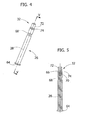
- the hinge-pin 26 has a cylindrical body with circular cross section having at a first end a widened head 64. At the opposite end, the pin 26 has a blind hole 66 sharing the axis 28.
- the pin 26 is provided on its external surface with an annular groove 68.
- the pin 26 has a constant external diameter, with the exception of the stretches in which the groove 68 and the head 64 are formed.
- the extension element 32 is configured as an element detached from the pin 26 and comprises a first cylindrical portion 70 and a second cylindrical portion 72, which are coaxial with respect to one another and are separated by a radial collar 74.
- the first cylindrical portion 70 has a smaller diameter than the second cylindrical portion 72, and the collar 74 projects in a radial direction beyond the external surface of the second cylindrical portion 72.
- the first cylindrical portion 70 is sized so as to establish a shape fit with the blind hole 66 formed at the end of the pin 26.
- the collar 74 preferably has an external diameter substantially equal to the external diameter of the pin 26.
- the third hinge element 30 is configured as element separate from the first hinge element 22 and the second hinge element 24 and comprises a monolithic body of metal material comprising a head 76, a spacing portion 78, and a coupling portion 80.
- the coupling portion 80 is shaped to be inserted by shape fit into the groove with undercut cross section 48 of the first hinge element 22.
- the spacing portion 78 has a height in the direction of the axis of articulation 28 slightly greater than the height of the articulation portion 54 of the second hinge element 24.
- the head 76 has a hole 82 intended to receive the second cylindrical portion 72 of the extension element 32.
- the head 76 of the third hinge element 30 is moreover provided with a fixing hole designed to receive a screw 84.
- the hinge 20 moreover comprises a washer 86 that is applied on the top front end 42 of the first hinge element 22.
- the washer 86 comprises an annular portion 88 and three integral arms 90, 92, 94, which extend in an axial direction from the annular portion 88.
- the washer 86 is described in a more detailed way in a simultaneous patent application filed in the name of the present applicant.
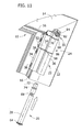
- the first hinge element 22 is fixed to the upright 12 by means of screws 38 according to modalities in themselves conventional. Then, the washer 86 is inserted into the seat 44, on the side of the top front end 42. The arms 90, 92, 94 of the washer 86 are inserted in the grooves 46 of the seat 44. Figure 7 shows the washer 86 inserted in the seat 44. Then, as illustrated in Figure 8 , the third hinge element 30 is fitted to the first hinge element 22, as illustrated in Figures 8 and 9 . The coupling portion 80 of the third hinge element 30 is inserted in the groove with undercut cross section 48 of the first hinge element 22.
- the third hinge element 30 is located in the correct position when the spacing portion 78 comes to bear upon the top front end of the first hinge element 22 ( Figure 9 ). In this condition, the third hinge element is fixed to the upright 12 by means of the screw 84, as illustrated in Figure 9 .
- the second hinge element 24 is inserted in the direction indicated by the arrow in Figure 10 in the space comprised between the head 76 of the third hinge element 30 and the top front end 42 of the second hinge element 22.
- the second hinge element 24 is positioned with the articulation seat 62 aligned to the articulation seat 36 and to the hole 82 of the third hinge element 30, as illustrated in Figure 11 .
- the extension element 32 is applied to the end of the pin 26, and the pin assumes the configuration illustrated in Figure 10 .
- the pin 26, with the corresponding extension element 22, is then inserted into the articulation seats, aligned with respect to one another, of the first and second hinge elements, in the direction indicated by the arrow in Figure 11 .
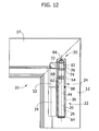
- the cross section of Figure 12 shows the hinge after complete insertion of the pin.
- the second cylindrical portion 72 of the extension element 32 engages the hole 82 of the third hinge element.
- the annular portion 88 of the washer 86 is comprised between the top front end of the first hinge element 22 and the bottom front end of the second hinge element 24.
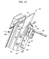
- the assembly is completed, as illustrated in Figures 13 and 14 , by screwing a grubscrew 96 in a transverse threaded hole 98 of the second hinge element 20.
- the threaded hole 98 is situated in a position corresponding to the annular groove 68 of the pin 26. Consequently, the internal end of the grubscrew 96 engages the annular groove 68 of the pin 26 as illustrated in Figure 14 .
- the procedure of assembly described previously refers to the complete hinge 20 of the reinforcement kit 30, 32.
- the hinge 20 can also be mounted without the reinforcement kit 30, 32.
- the hinge 20 becomes a conventional two-leaf hinge.
- the top end of the pin 26 without the extension element, is substantially flush with the top front end 60 of the second hinge element 24.
- the use of the reinforcement kit 30, 32 enables conversion of the two-leaf hinge into a three-leaf hinge, with consequent increase of the maximum load that the hinge can withstand.
- the pin 26 is subjected to shearing stress instead of bending stress, and its strength increases.
- the two-leaf hinge without the reinforcement kit can have a maximum load-bearing capacity of 100 kg
- the hinge with the reinforcement kit can have a maximum load-bearing capacity in the region of 130 kg.
- the reinforcement kit 30, 32 consequently enables increase in the load of the hinge in a simple and inexpensive way.
- the reinforcement kit 30, 32 can be mounted at any moment, also with the door or window already in place. In fact, it is sufficient to slide out the pin 26 of the two-leaf hinge and proceed with the sequence of assembly described previously.
Landscapes
- Engineering & Computer Science (AREA)
- Mechanical Engineering (AREA)
- Hinges (AREA)
Priority Applications (14)
| Application Number | Priority Date | Filing Date | Title |
|---|---|---|---|
| DE602008003091T DE602008003091D1 (de) | 2008-01-31 | 2008-01-31 | Ein Scharnier für Türen oder Fenster |
| EP08425058A EP2085548B1 (de) | 2008-01-31 | 2008-01-31 | Ein Scharnier für Türen oder Fenster |
| PL08425058T PL2085548T3 (pl) | 2008-01-31 | 2008-01-31 | Zawias dla drzwi lub okien |
| ES08425058T ES2353041T3 (es) | 2008-01-31 | 2008-01-31 | Bisagra para puertas o ventanas. |
| PT08425058T PT2085548E (pt) | 2008-01-31 | 2008-01-31 | Uma dobradiça para portas ou janelas |
| AT08425058T ATE485433T1 (de) | 2008-01-31 | 2008-01-31 | Ein scharnier für türen oder fenster |
| IL196356A IL196356A0 (en) | 2008-01-31 | 2009-01-05 | A hinge for doors or windows |
| TW098101285A TW200938715A (en) | 2008-01-31 | 2009-01-14 | A hinge for doors or windows |
| CA002650361A CA2650361A1 (en) | 2008-01-31 | 2009-01-22 | A hinge for doors or windows |
| BRPI0900146-8A BRPI0900146A2 (pt) | 2008-01-31 | 2009-01-28 | dobradiças para portas e janelas |
| US12/361,848 US7996960B2 (en) | 2008-01-31 | 2009-01-29 | Hinge for doors or windows |
| ARP090100296A AR070849A1 (es) | 2008-01-31 | 2009-01-29 | Bisagra para puertas o ventanas |
| RU2009103165/12A RU2009103165A (ru) | 2008-01-31 | 2009-01-30 | Петля для дверей или окон |
| CNA2009100037109A CN101498189A (zh) | 2008-01-31 | 2009-02-01 | 用于门或窗的铰链 |
Applications Claiming Priority (1)
| Application Number | Priority Date | Filing Date | Title |
|---|---|---|---|
| EP08425058A EP2085548B1 (de) | 2008-01-31 | 2008-01-31 | Ein Scharnier für Türen oder Fenster |
Publications (2)
| Publication Number | Publication Date |
|---|---|
| EP2085548A1 true EP2085548A1 (de) | 2009-08-05 |
| EP2085548B1 EP2085548B1 (de) | 2010-10-20 |
Family
ID=39768951
Family Applications (1)
| Application Number | Title | Priority Date | Filing Date |
|---|---|---|---|
| EP08425058A Active EP2085548B1 (de) | 2008-01-31 | 2008-01-31 | Ein Scharnier für Türen oder Fenster |
Country Status (14)
| Country | Link |
|---|---|
| US (1) | US7996960B2 (de) |
| EP (1) | EP2085548B1 (de) |
| CN (1) | CN101498189A (de) |
| AR (1) | AR070849A1 (de) |
| AT (1) | ATE485433T1 (de) |
| BR (1) | BRPI0900146A2 (de) |
| CA (1) | CA2650361A1 (de) |
| DE (1) | DE602008003091D1 (de) |
| ES (1) | ES2353041T3 (de) |
| IL (1) | IL196356A0 (de) |
| PL (1) | PL2085548T3 (de) |
| PT (1) | PT2085548E (de) |
| RU (1) | RU2009103165A (de) |
| TW (1) | TW200938715A (de) |
Cited By (1)
| Publication number | Priority date | Publication date | Assignee | Title |
|---|---|---|---|---|
| WO2013026649A1 (de) * | 2011-08-19 | 2013-02-28 | Roto Frank Ag | Lagerband |
Families Citing this family (5)
| Publication number | Priority date | Publication date | Assignee | Title |
|---|---|---|---|---|
| US9234375B1 (en) * | 2014-10-06 | 2016-01-12 | Chin-Hsing Horng | Hinge structure with male shaft position adjustability |
| US20160130850A1 (en) * | 2014-11-12 | 2016-05-12 | Duncan Bolt Co. | Tamper resitant hinge pin retention |
| IT201800006082A1 (it) * | 2018-06-06 | 2019-12-06 | Gruppo cerniere per ante | |
| CN109403770B (zh) * | 2018-11-30 | 2023-09-22 | 宁波市维特建筑五金有限公司 | 一种铝木复合门窗用隐形铰链 |
| CN216960402U (zh) * | 2021-11-03 | 2022-07-12 | 华为技术有限公司 | 阻尼销及机柜 |
Citations (4)
| Publication number | Priority date | Publication date | Assignee | Title |
|---|---|---|---|---|
| FR2214316A5 (de) * | 1972-12-20 | 1974-08-09 | Frank Gmbh Wilh | |
| DE4302599C1 (de) * | 1993-01-30 | 1994-02-24 | Bilstein August Gmbh Co Kg | Vorrichtung zum Verbinden eines Ausstellenkers mit einem Fenster- oder Türrahmen |
| EP0733762A1 (de) * | 1995-03-22 | 1996-09-25 | GIESSE S.p.A. | Scharnier für metallische Tür- und Fensterrahmen mit zwei Öffnungsmöglichkeiten |
| EP1085155A2 (de) * | 1997-04-23 | 2001-03-21 | Ferco International Ferrures et Serrures de Bâtiment | Beschlag mit Tragarm oder Ausstellarm zur Lagerung eines Drehflügels oder Dreh-Kippflügels |
Family Cites Families (10)
| Publication number | Priority date | Publication date | Assignee | Title |
|---|---|---|---|---|
| US3263269A (en) * | 1964-09-02 | 1966-08-02 | Welbourne D Mcgahee | Safety hinges |
| SE453846B (sv) * | 1983-09-19 | 1988-03-07 | Scharwaechter Gmbh Co Kg | Dorrgangjern for motorfordon |
| DE3532423A1 (de) * | 1985-09-11 | 1987-03-12 | Scharwaechter Gmbh Co Kg | Anlenkung fuer aushaengbare kraftwagentueren |
| FR2614923B1 (fr) * | 1987-05-05 | 1993-12-31 | Ferco Internal Usine Ferrures Ba | Ferrures d'articulation d'un ouvrant oscillo-battant d'une porte, fenetre ou analogue |
| EP0314616A1 (de) * | 1987-10-28 | 1989-05-03 | Gutknecht S.A. | Scharnierband zum Aufhängen von Flügeln |
| IT1234629B (it) * | 1989-03-10 | 1992-05-26 | Fapim Snc | Cerniera regolabile con funzione antiscasso adatta per porte e finestre in genere |
| FR2652608A1 (fr) * | 1989-10-02 | 1991-04-05 | Fercq Internal Usine Ferrures | Palier de compas pour ouvrant oscillo-battant de portes, fenetres ou analogues. |
| US5150500A (en) * | 1991-07-11 | 1992-09-29 | Southco, Inc. | Adjustable lift-off hinge |
| DE4216689A1 (de) * | 1992-05-20 | 1993-11-25 | Hautau Gmbh W | Verdeckt eingebautes Scharniergelenk |
| US5819372A (en) * | 1996-12-23 | 1998-10-13 | Microsoft Corporation | Butt hinge with integrally formed butt straps |
-
2008
- 2008-01-31 PT PT08425058T patent/PT2085548E/pt unknown
- 2008-01-31 DE DE602008003091T patent/DE602008003091D1/de active Active
- 2008-01-31 EP EP08425058A patent/EP2085548B1/de active Active
- 2008-01-31 ES ES08425058T patent/ES2353041T3/es active Active
- 2008-01-31 PL PL08425058T patent/PL2085548T3/pl unknown
- 2008-01-31 AT AT08425058T patent/ATE485433T1/de not_active IP Right Cessation
-
2009
- 2009-01-05 IL IL196356A patent/IL196356A0/en unknown
- 2009-01-14 TW TW098101285A patent/TW200938715A/zh unknown
- 2009-01-22 CA CA002650361A patent/CA2650361A1/en not_active Abandoned
- 2009-01-28 BR BRPI0900146-8A patent/BRPI0900146A2/pt not_active Application Discontinuation
- 2009-01-29 AR ARP090100296A patent/AR070849A1/es unknown
- 2009-01-29 US US12/361,848 patent/US7996960B2/en not_active Expired - Fee Related
- 2009-01-30 RU RU2009103165/12A patent/RU2009103165A/ru not_active Application Discontinuation
- 2009-02-01 CN CNA2009100037109A patent/CN101498189A/zh active Pending
Patent Citations (4)
| Publication number | Priority date | Publication date | Assignee | Title |
|---|---|---|---|---|
| FR2214316A5 (de) * | 1972-12-20 | 1974-08-09 | Frank Gmbh Wilh | |
| DE4302599C1 (de) * | 1993-01-30 | 1994-02-24 | Bilstein August Gmbh Co Kg | Vorrichtung zum Verbinden eines Ausstellenkers mit einem Fenster- oder Türrahmen |
| EP0733762A1 (de) * | 1995-03-22 | 1996-09-25 | GIESSE S.p.A. | Scharnier für metallische Tür- und Fensterrahmen mit zwei Öffnungsmöglichkeiten |
| EP1085155A2 (de) * | 1997-04-23 | 2001-03-21 | Ferco International Ferrures et Serrures de Bâtiment | Beschlag mit Tragarm oder Ausstellarm zur Lagerung eines Drehflügels oder Dreh-Kippflügels |
Cited By (1)
| Publication number | Priority date | Publication date | Assignee | Title |
|---|---|---|---|---|
| WO2013026649A1 (de) * | 2011-08-19 | 2013-02-28 | Roto Frank Ag | Lagerband |
Also Published As
| Publication number | Publication date |
|---|---|
| ATE485433T1 (de) | 2010-11-15 |
| CN101498189A (zh) | 2009-08-05 |
| US20090193623A1 (en) | 2009-08-06 |
| IL196356A0 (en) | 2009-11-18 |
| RU2009103165A (ru) | 2010-08-10 |
| PL2085548T3 (pl) | 2011-03-31 |
| ES2353041T3 (es) | 2011-02-24 |
| AR070849A1 (es) | 2010-05-12 |
| US7996960B2 (en) | 2011-08-16 |
| DE602008003091D1 (de) | 2010-12-02 |
| CA2650361A1 (en) | 2009-07-31 |
| EP2085548B1 (de) | 2010-10-20 |
| TW200938715A (en) | 2009-09-16 |
| BRPI0900146A2 (pt) | 2009-09-22 |
| PT2085548E (pt) | 2010-12-21 |
Similar Documents
| Publication | Publication Date | Title |
|---|---|---|
| US7996960B2 (en) | Hinge for doors or windows | |
| US20140047673A1 (en) | Adjustable hinge | |
| EP2060713A1 (de) | Einbruchsicheres System für Fenster- und Türrahmen | |
| PL213636B1 (pl) | Zespól wsporników rolety i zacisk wspornika rolety | |
| EP2682551A2 (de) | Verstellbares Scharnier für Fenster und Türen | |
| HU224231B1 (hu) | Szerelvénycsoport csuklópánttal, valamint ajtó, ablak és hasonló | |
| EP2085549A1 (de) | Ein Scharnier für Türen oder Fenster | |
| EP1612356B1 (de) | Scharniervorrichtung für Fenster und Türe | |
| US20040107643A1 (en) | Plug for counterbalancing mechanism, door assembly including the same and method of installing associated thereto | |
| CN213391659U (zh) | 一种平开窗安全限位器 | |
| KR20020044359A (ko) | 백도어의 힌지구조 | |
| US20090119874A1 (en) | Snap-On Window Balance Terminal Clip | |
| EP3628805B1 (de) | Türscharnier | |
| CN219138728U (zh) | 一种适用于内开内倒的拉杆 | |
| CN217233163U (zh) | 一种带转轴的防盗合页 | |
| CN220769204U (zh) | 一种手动上翻门铰链组件 | |
| KR102918772B1 (ko) | 도어용 힌지어셈블리 | |
| CN223190260U (zh) | 一种门窗用铰链 | |
| CN213654559U (zh) | 便于调节自带锁定功能的隐藏式斜拉杆总成 | |
| EP4715151A1 (de) | Fensterbeschläge und verfahren zur drehbaren verbindung eines drehbaren arms mit einem bestückteil | |
| EP2105565B1 (de) | Antrieb für einen flügel eines fensters | |
| CN220434509U (zh) | 一种上悬铰链 | |
| HU227028B1 (en) | Hinge for doors and windows, particularly for swing doors | |
| CN214532443U (zh) | 一种新型铰链 | |
| EP3252254A1 (de) | Scharnier |
Legal Events
| Date | Code | Title | Description |
|---|---|---|---|
| PUAI | Public reference made under article 153(3) epc to a published international application that has entered the european phase |
Free format text: ORIGINAL CODE: 0009012 |
|
| 17P | Request for examination filed |
Effective date: 20081219 |
|
| AK | Designated contracting states |
Kind code of ref document: A1 Designated state(s): AT BE BG CH CY CZ DE DK EE ES FI FR GB GR HR HU IE IS IT LI LT LU LV MC MT NL NO PL PT RO SE SI SK TR |
|
| AX | Request for extension of the european patent |
Extension state: AL BA MK RS |
|
| AKX | Designation fees paid |
Designated state(s): AT BE BG CH CY CZ DE DK EE ES FI FR GB GR HR HU IE IS IT LI LT LU LV MC MT NL NO PL PT RO SE SI SK TR |
|
| GRAP | Despatch of communication of intention to grant a patent |
Free format text: ORIGINAL CODE: EPIDOSNIGR1 |
|
| GRAS | Grant fee paid |
Free format text: ORIGINAL CODE: EPIDOSNIGR3 |
|
| GRAA | (expected) grant |
Free format text: ORIGINAL CODE: 0009210 |
|
| AK | Designated contracting states |
Kind code of ref document: B1 Designated state(s): AT BE BG CH CY CZ DE DK EE ES FI FR GB GR HR HU IE IS IT LI LT LU LV MC MT NL NO PL PT RO SE SI SK TR |
|
| REG | Reference to a national code |
Ref country code: GB Ref legal event code: FG4D |
|
| REG | Reference to a national code |
Ref country code: CH Ref legal event code: EP |
|
| REG | Reference to a national code |
Ref country code: IE Ref legal event code: FG4D |
|
| REF | Corresponds to: |
Ref document number: 602008003091 Country of ref document: DE Date of ref document: 20101202 Kind code of ref document: P |
|
| REG | Reference to a national code |
Ref country code: PT Ref legal event code: SC4A Free format text: AVAILABILITY OF NATIONAL TRANSLATION Effective date: 20101214 Ref country code: GR Ref legal event code: EP Ref document number: 20100402594 Country of ref document: GR |
|
| REG | Reference to a national code |
Ref country code: ES Ref legal event code: FG2A Effective date: 20110214 |
|
| REG | Reference to a national code |
Ref country code: NL Ref legal event code: VDEP Effective date: 20101020 |
|
| LTIE | Lt: invalidation of european patent or patent extension |
Effective date: 20101020 |
|
| REG | Reference to a national code |
Ref country code: PL Ref legal event code: T3 |
|
| PG25 | Lapsed in a contracting state [announced via postgrant information from national office to epo] |
Ref country code: NO Free format text: LAPSE BECAUSE OF FAILURE TO SUBMIT A TRANSLATION OF THE DESCRIPTION OR TO PAY THE FEE WITHIN THE PRESCRIBED TIME-LIMIT Effective date: 20110120 Ref country code: LT Free format text: LAPSE BECAUSE OF FAILURE TO SUBMIT A TRANSLATION OF THE DESCRIPTION OR TO PAY THE FEE WITHIN THE PRESCRIBED TIME-LIMIT Effective date: 20101020 |
|
| PG25 | Lapsed in a contracting state [announced via postgrant information from national office to epo] |
Ref country code: FI Free format text: LAPSE BECAUSE OF FAILURE TO SUBMIT A TRANSLATION OF THE DESCRIPTION OR TO PAY THE FEE WITHIN THE PRESCRIBED TIME-LIMIT Effective date: 20101020 Ref country code: BG Free format text: LAPSE BECAUSE OF FAILURE TO SUBMIT A TRANSLATION OF THE DESCRIPTION OR TO PAY THE FEE WITHIN THE PRESCRIBED TIME-LIMIT Effective date: 20110120 Ref country code: NL Free format text: LAPSE BECAUSE OF FAILURE TO SUBMIT A TRANSLATION OF THE DESCRIPTION OR TO PAY THE FEE WITHIN THE PRESCRIBED TIME-LIMIT Effective date: 20101020 Ref country code: SI Free format text: LAPSE BECAUSE OF FAILURE TO SUBMIT A TRANSLATION OF THE DESCRIPTION OR TO PAY THE FEE WITHIN THE PRESCRIBED TIME-LIMIT Effective date: 20101020 Ref country code: AT Free format text: LAPSE BECAUSE OF FAILURE TO SUBMIT A TRANSLATION OF THE DESCRIPTION OR TO PAY THE FEE WITHIN THE PRESCRIBED TIME-LIMIT Effective date: 20101020 Ref country code: IS Free format text: LAPSE BECAUSE OF FAILURE TO SUBMIT A TRANSLATION OF THE DESCRIPTION OR TO PAY THE FEE WITHIN THE PRESCRIBED TIME-LIMIT Effective date: 20110220 Ref country code: LV Free format text: LAPSE BECAUSE OF FAILURE TO SUBMIT A TRANSLATION OF THE DESCRIPTION OR TO PAY THE FEE WITHIN THE PRESCRIBED TIME-LIMIT Effective date: 20101020 Ref country code: HR Free format text: LAPSE BECAUSE OF FAILURE TO SUBMIT A TRANSLATION OF THE DESCRIPTION OR TO PAY THE FEE WITHIN THE PRESCRIBED TIME-LIMIT Effective date: 20101020 Ref country code: SE Free format text: LAPSE BECAUSE OF FAILURE TO SUBMIT A TRANSLATION OF THE DESCRIPTION OR TO PAY THE FEE WITHIN THE PRESCRIBED TIME-LIMIT Effective date: 20101020 |
|
| PG25 | Lapsed in a contracting state [announced via postgrant information from national office to epo] |
Ref country code: CZ Free format text: LAPSE BECAUSE OF FAILURE TO SUBMIT A TRANSLATION OF THE DESCRIPTION OR TO PAY THE FEE WITHIN THE PRESCRIBED TIME-LIMIT Effective date: 20101020 Ref country code: EE Free format text: LAPSE BECAUSE OF FAILURE TO SUBMIT A TRANSLATION OF THE DESCRIPTION OR TO PAY THE FEE WITHIN THE PRESCRIBED TIME-LIMIT Effective date: 20101020 |
|
| PLBE | No opposition filed within time limit |
Free format text: ORIGINAL CODE: 0009261 |
|
| STAA | Information on the status of an ep patent application or granted ep patent |
Free format text: STATUS: NO OPPOSITION FILED WITHIN TIME LIMIT |
|
| PG25 | Lapsed in a contracting state [announced via postgrant information from national office to epo] |
Ref country code: RO Free format text: LAPSE BECAUSE OF FAILURE TO SUBMIT A TRANSLATION OF THE DESCRIPTION OR TO PAY THE FEE WITHIN THE PRESCRIBED TIME-LIMIT Effective date: 20101020 Ref country code: MC Free format text: LAPSE BECAUSE OF NON-PAYMENT OF DUE FEES Effective date: 20110131 Ref country code: SK Free format text: LAPSE BECAUSE OF FAILURE TO SUBMIT A TRANSLATION OF THE DESCRIPTION OR TO PAY THE FEE WITHIN THE PRESCRIBED TIME-LIMIT Effective date: 20101020 Ref country code: DK Free format text: LAPSE BECAUSE OF FAILURE TO SUBMIT A TRANSLATION OF THE DESCRIPTION OR TO PAY THE FEE WITHIN THE PRESCRIBED TIME-LIMIT Effective date: 20101020 |
|
| 26N | No opposition filed |
Effective date: 20110721 |
|
| REG | Reference to a national code |
Ref country code: IE Ref legal event code: MM4A |
|
| REG | Reference to a national code |
Ref country code: DE Ref legal event code: R097 Ref document number: 602008003091 Country of ref document: DE Effective date: 20110721 |
|
| PG25 | Lapsed in a contracting state [announced via postgrant information from national office to epo] |
Ref country code: MT Free format text: LAPSE BECAUSE OF FAILURE TO SUBMIT A TRANSLATION OF THE DESCRIPTION OR TO PAY THE FEE WITHIN THE PRESCRIBED TIME-LIMIT Effective date: 20101020 |
|
| PG25 | Lapsed in a contracting state [announced via postgrant information from national office to epo] |
Ref country code: IE Free format text: LAPSE BECAUSE OF NON-PAYMENT OF DUE FEES Effective date: 20110131 |
|
| PGFP | Annual fee paid to national office [announced via postgrant information from national office to epo] |
Ref country code: TR Payment date: 20120109 Year of fee payment: 5 |
|
| REG | Reference to a national code |
Ref country code: CH Ref legal event code: PL |
|
| PG25 | Lapsed in a contracting state [announced via postgrant information from national office to epo] |
Ref country code: LI Free format text: LAPSE BECAUSE OF NON-PAYMENT OF DUE FEES Effective date: 20120131 Ref country code: CH Free format text: LAPSE BECAUSE OF NON-PAYMENT OF DUE FEES Effective date: 20120131 |
|
| PGFP | Annual fee paid to national office [announced via postgrant information from national office to epo] |
Ref country code: PL Payment date: 20121128 Year of fee payment: 6 Ref country code: GR Payment date: 20121214 Year of fee payment: 6 |
|
| PGFP | Annual fee paid to national office [announced via postgrant information from national office to epo] |
Ref country code: GB Payment date: 20130130 Year of fee payment: 6 Ref country code: ES Payment date: 20130207 Year of fee payment: 6 |
|
| PG25 | Lapsed in a contracting state [announced via postgrant information from national office to epo] |
Ref country code: LU Free format text: LAPSE BECAUSE OF NON-PAYMENT OF DUE FEES Effective date: 20110131 Ref country code: CY Free format text: LAPSE BECAUSE OF FAILURE TO SUBMIT A TRANSLATION OF THE DESCRIPTION OR TO PAY THE FEE WITHIN THE PRESCRIBED TIME-LIMIT Effective date: 20101020 |
|
| PGFP | Annual fee paid to national office [announced via postgrant information from national office to epo] |
Ref country code: BE Payment date: 20130114 Year of fee payment: 6 |
|
| PGFP | Annual fee paid to national office [announced via postgrant information from national office to epo] |
Ref country code: PT Payment date: 20130131 Year of fee payment: 6 |
|
| PG25 | Lapsed in a contracting state [announced via postgrant information from national office to epo] |
Ref country code: HU Free format text: LAPSE BECAUSE OF FAILURE TO SUBMIT A TRANSLATION OF THE DESCRIPTION OR TO PAY THE FEE WITHIN THE PRESCRIBED TIME-LIMIT Effective date: 20101020 |
|
| BERE | Be: lapsed |
Owner name: SAVIO S.P.A. Effective date: 20140131 |
|
| REG | Reference to a national code |
Ref country code: PT Ref legal event code: MM4A Free format text: LAPSE DUE TO NON-PAYMENT OF FEES Effective date: 20140731 |
|
| GBPC | Gb: european patent ceased through non-payment of renewal fee |
Effective date: 20140131 |
|
| REG | Reference to a national code |
Ref country code: GR Ref legal event code: ML Ref document number: 20100402594 Country of ref document: GR Effective date: 20140801 |
|
| PG25 | Lapsed in a contracting state [announced via postgrant information from national office to epo] |
Ref country code: GR Free format text: LAPSE BECAUSE OF NON-PAYMENT OF DUE FEES Effective date: 20140801 |
|
| PG25 | Lapsed in a contracting state [announced via postgrant information from national office to epo] |
Ref country code: GB Free format text: LAPSE BECAUSE OF NON-PAYMENT OF DUE FEES Effective date: 20140131 |
|
| PG25 | Lapsed in a contracting state [announced via postgrant information from national office to epo] |
Ref country code: PT Free format text: LAPSE BECAUSE OF NON-PAYMENT OF DUE FEES Effective date: 20140731 |
|
| PG25 | Lapsed in a contracting state [announced via postgrant information from national office to epo] |
Ref country code: BE Free format text: LAPSE BECAUSE OF NON-PAYMENT OF DUE FEES Effective date: 20140131 |
|
| REG | Reference to a national code |
Ref country code: PL Ref legal event code: LAPE |
|
| PG25 | Lapsed in a contracting state [announced via postgrant information from national office to epo] |
Ref country code: PL Free format text: LAPSE BECAUSE OF NON-PAYMENT OF DUE FEES Effective date: 20140131 |
|
| REG | Reference to a national code |
Ref country code: ES Ref legal event code: FD2A Effective date: 20151002 |
|
| PG25 | Lapsed in a contracting state [announced via postgrant information from national office to epo] |
Ref country code: ES Free format text: LAPSE BECAUSE OF NON-PAYMENT OF DUE FEES Effective date: 20140201 |
|
| REG | Reference to a national code |
Ref country code: FR Ref legal event code: PLFP Year of fee payment: 9 |
|
| REG | Reference to a national code |
Ref country code: FR Ref legal event code: PLFP Year of fee payment: 10 |
|
| PGFP | Annual fee paid to national office [announced via postgrant information from national office to epo] |
Ref country code: FR Payment date: 20170126 Year of fee payment: 10 |
|
| PGFP | Annual fee paid to national office [announced via postgrant information from national office to epo] |
Ref country code: DE Payment date: 20170331 Year of fee payment: 10 |
|
| PG25 | Lapsed in a contracting state [announced via postgrant information from national office to epo] |
Ref country code: TR Free format text: LAPSE BECAUSE OF NON-PAYMENT OF DUE FEES Effective date: 20140131 |
|
| REG | Reference to a national code |
Ref country code: DE Ref legal event code: R119 Ref document number: 602008003091 Country of ref document: DE |
|
| PG25 | Lapsed in a contracting state [announced via postgrant information from national office to epo] |
Ref country code: DE Free format text: LAPSE BECAUSE OF NON-PAYMENT OF DUE FEES Effective date: 20180801 Ref country code: FR Free format text: LAPSE BECAUSE OF NON-PAYMENT OF DUE FEES Effective date: 20180131 |
|
| REG | Reference to a national code |
Ref country code: FR Ref legal event code: ST Effective date: 20180928 |
|
| PGFP | Annual fee paid to national office [announced via postgrant information from national office to epo] |
Ref country code: IT Payment date: 20250113 Year of fee payment: 18 |