EP2085618A2 - Außeneinheit einer Klimaanlage und Lüfter dafür - Google Patents
Außeneinheit einer Klimaanlage und Lüfter dafür Download PDFInfo
- Publication number
- EP2085618A2 EP2085618A2 EP09151163A EP09151163A EP2085618A2 EP 2085618 A2 EP2085618 A2 EP 2085618A2 EP 09151163 A EP09151163 A EP 09151163A EP 09151163 A EP09151163 A EP 09151163A EP 2085618 A2 EP2085618 A2 EP 2085618A2
- Authority
- EP
- European Patent Office
- Prior art keywords
- hub shaft
- shaft
- air
- driving
- fan
- Prior art date
- Legal status (The legal status is an assumption and is not a legal conclusion. Google has not performed a legal analysis and makes no representation as to the accuracy of the status listed.)
- Granted
Links
Images


Classifications
-
- F—MECHANICAL ENGINEERING; LIGHTING; HEATING; WEAPONS; BLASTING
- F04—POSITIVE - DISPLACEMENT MACHINES FOR LIQUIDS; PUMPS FOR LIQUIDS OR ELASTIC FLUIDS
- F04D—NON-POSITIVE-DISPLACEMENT PUMPS
- F04D29/00—Details, component parts, or accessories
- F04D29/26—Rotors specially for elastic fluids
- F04D29/263—Rotors specially for elastic fluids mounting fan or blower rotors on shafts
-
- F—MECHANICAL ENGINEERING; LIGHTING; HEATING; WEAPONS; BLASTING
- F04—POSITIVE - DISPLACEMENT MACHINES FOR LIQUIDS; PUMPS FOR LIQUIDS OR ELASTIC FLUIDS
- F04D—NON-POSITIVE-DISPLACEMENT PUMPS
- F04D29/00—Details, component parts, or accessories
- F04D29/26—Rotors specially for elastic fluids
- F04D29/32—Rotors specially for elastic fluids for axial flow pumps
- F04D29/325—Rotors specially for elastic fluids for axial flow pumps for axial flow fans
- F04D29/329—Details of the hub
-
- F—MECHANICAL ENGINEERING; LIGHTING; HEATING; WEAPONS; BLASTING
- F04—POSITIVE - DISPLACEMENT MACHINES FOR LIQUIDS; PUMPS FOR LIQUIDS OR ELASTIC FLUIDS
- F04D—NON-POSITIVE-DISPLACEMENT PUMPS
- F04D29/00—Details, component parts, or accessories
- F04D29/60—Mounting; Assembling; Disassembling
- F04D29/64—Mounting; Assembling; Disassembling of axial pumps
- F04D29/644—Mounting; Assembling; Disassembling of axial pumps especially adapted for elastic fluid pumps
- F04D29/646—Mounting or removal of fans
-
- F—MECHANICAL ENGINEERING; LIGHTING; HEATING; WEAPONS; BLASTING
- F04—POSITIVE - DISPLACEMENT MACHINES FOR LIQUIDS; PUMPS FOR LIQUIDS OR ELASTIC FLUIDS
- F04D—NON-POSITIVE-DISPLACEMENT PUMPS
- F04D29/00—Details, component parts, or accessories
- F04D29/66—Combating cavitation, whirls, noise, vibration or the like; Balancing
- F04D29/661—Combating cavitation, whirls, noise, vibration or the like; Balancing especially adapted for elastic fluid pumps
- F04D29/663—Sound attenuation
-
- F—MECHANICAL ENGINEERING; LIGHTING; HEATING; WEAPONS; BLASTING
- F04—POSITIVE - DISPLACEMENT MACHINES FOR LIQUIDS; PUMPS FOR LIQUIDS OR ELASTIC FLUIDS
- F04D—NON-POSITIVE-DISPLACEMENT PUMPS
- F04D29/00—Details, component parts, or accessories
- F04D29/66—Combating cavitation, whirls, noise, vibration or the like; Balancing
- F04D29/661—Combating cavitation, whirls, noise, vibration or the like; Balancing especially adapted for elastic fluid pumps
- F04D29/668—Combating cavitation, whirls, noise, vibration or the like; Balancing especially adapted for elastic fluid pumps damping or preventing mechanical vibrations
-
- F—MECHANICAL ENGINEERING; LIGHTING; HEATING; WEAPONS; BLASTING
- F24—HEATING; RANGES; VENTILATING
- F24F—AIR-CONDITIONING; AIR-HUMIDIFICATION; VENTILATION; USE OF AIR CURRENTS FOR SCREENING
- F24F1/00—Room units for air-conditioning, e.g. separate or self-contained units or units receiving primary air from a central station
- F24F1/06—Separate outdoor units, e.g. outdoor unit to be linked to a separate room comprising a compressor and a heat exchanger
- F24F1/38—Fan details of outdoor units, e.g. bell-mouth shaped inlets or fan mountings
-
- F—MECHANICAL ENGINEERING; LIGHTING; HEATING; WEAPONS; BLASTING
- F24—HEATING; RANGES; VENTILATING
- F24F—AIR-CONDITIONING; AIR-HUMIDIFICATION; VENTILATION; USE OF AIR CURRENTS FOR SCREENING
- F24F1/00—Room units for air-conditioning, e.g. separate or self-contained units or units receiving primary air from a central station
- F24F1/06—Separate outdoor units, e.g. outdoor unit to be linked to a separate room comprising a compressor and a heat exchanger
- F24F1/40—Vibration or noise prevention at outdoor units
-
- F—MECHANICAL ENGINEERING; LIGHTING; HEATING; WEAPONS; BLASTING
- F24—HEATING; RANGES; VENTILATING
- F24F—AIR-CONDITIONING; AIR-HUMIDIFICATION; VENTILATION; USE OF AIR CURRENTS FOR SCREENING
- F24F1/00—Room units for air-conditioning, e.g. separate or self-contained units or units receiving primary air from a central station
- F24F1/06—Separate outdoor units, e.g. outdoor unit to be linked to a separate room comprising a compressor and a heat exchanger
- F24F1/46—Component arrangements in separate outdoor units
- F24F1/48—Component arrangements in separate outdoor units characterised by air airflow, e.g. inlet or outlet airflow
- F24F1/50—Component arrangements in separate outdoor units characterised by air airflow, e.g. inlet or outlet airflow with outlet air in upward direction
-
- F—MECHANICAL ENGINEERING; LIGHTING; HEATING; WEAPONS; BLASTING
- F24—HEATING; RANGES; VENTILATING
- F24F—AIR-CONDITIONING; AIR-HUMIDIFICATION; VENTILATION; USE OF AIR CURRENTS FOR SCREENING
- F24F7/00—Ventilation
- F24F7/007—Ventilation with forced flow
-
- F—MECHANICAL ENGINEERING; LIGHTING; HEATING; WEAPONS; BLASTING
- F05—INDEXING SCHEMES RELATING TO ENGINES OR PUMPS IN VARIOUS SUBCLASSES OF CLASSES F01-F04
- F05D—INDEXING SCHEME FOR ASPECTS RELATING TO NON-POSITIVE-DISPLACEMENT MACHINES OR ENGINES, GAS-TURBINES OR JET-PROPULSION PLANTS
- F05D2210/00—Working fluids
- F05D2210/10—Kind or type
- F05D2210/12—Kind or type gaseous, i.e. compressible
-
- F—MECHANICAL ENGINEERING; LIGHTING; HEATING; WEAPONS; BLASTING
- F05—INDEXING SCHEMES RELATING TO ENGINES OR PUMPS IN VARIOUS SUBCLASSES OF CLASSES F01-F04
- F05D—INDEXING SCHEME FOR ASPECTS RELATING TO NON-POSITIVE-DISPLACEMENT MACHINES OR ENGINES, GAS-TURBINES OR JET-PROPULSION PLANTS
- F05D2240/00—Components
- F05D2240/20—Rotors
-
- F—MECHANICAL ENGINEERING; LIGHTING; HEATING; WEAPONS; BLASTING
- F05—INDEXING SCHEMES RELATING TO ENGINES OR PUMPS IN VARIOUS SUBCLASSES OF CLASSES F01-F04
- F05D—INDEXING SCHEME FOR ASPECTS RELATING TO NON-POSITIVE-DISPLACEMENT MACHINES OR ENGINES, GAS-TURBINES OR JET-PROPULSION PLANTS
- F05D2260/00—Function
- F05D2260/96—Preventing, counteracting or reducing vibration or noise
Definitions
- the present invention relates to an outdoor unit of an air-conditioner.
- Air-conditioners are devices for adjusting a state of air such that air in a certain space is maintained for people to live in an agreeable condition.
- the air-conditioner performs a function of managing to maintain temperature and moisture of the certain space at a certain level by absorbing or releasing heat in the space. In the process, the air-conditioner should externally release heat absorbed from the space or absorb heat from the exterior, so it requires an outdoor unit to perform such function.
- the outdoor unit exchanges heat with the outside, and in order to effectively perform heat exchanging, air in the interior of the outdoor unit should be properly exchanged with external air to maintain a temperature difference of a certain level between a heat exchanger within the outdoor unit and air within the outdoor unit.
- a device for circulating air by externally discharging air within the outdoor unit forcibly is required, and a fan performs such function.
- the fan forms a pressure difference for air circulation upon receiving rotatory power from a driving source. Because the efficiency of discharging air, noise, vibration, and the like, differ depending on the shape or structure of the fan, the shape of the fan should be determined from the point of view of fluid mechanics.
- the fan is coupled with a driving shaft of the driving source, so an operation efficiency for the coupling should be also considered in designing the shape of the fan.
- the most effective configuration of the fan should be determined in consideration of the factors such as energy efficiency, vibration, noise, operation efficiency, or the like, for which research is ongoing, but many problems are yet to be solved.
- an object of the present invention is to provide an outdoor fan for an air-conditioner capable of increasing an operation efficiency, improving an energy efficiency by reducing a side circulation flow, and reducing vibration, noise, or the like.
- an outdoor fan for an air-conditioner including: a hub shaft with a side hole; and rotary blades that convert rotatory power received from the hub shaft into a pressure difference
- the hub shaft includes a main plate unit perpendicular to the hub shaft and, positioned at a front side compared with a virtual plane including the side hole, and covering at least a portion of the hub shaft.
- the side hole may be a space for an operation of coupling a driving shaft of a driving source and the hub shaft such that the driving shaft is inserted from a rear side of the hub shaft and the hub shaft receives the rotatory power from the driving shaft.
- the hub shaft may include an opening formed at a rear side of the main plate unit of the hub shaft.
- the hub shaft may include a projection with a central hole formed at the center of the opening to allow the driving shaft of the driving source to be inserted thereinto.
- a first coupling hole may be formed at the side of the projection, a second coupling hole may be formed at a position corresponding to the first coupling hole at the side of the driving shaft, and the fan may further include a driving shaft coupling member that couples the driving shaft and the hub shaft via the first and second coupling holes.
- an outdoor unit for an air-conditioner including: a cabinet; a driving source disposed within the cabinet and generating rotatory power; a hub shaft disposed in front of the driving source to receive rotatory power from the driving source; and a fan forming a pressure difference received from the hub shaft; wherein the distance between the driving source and the fan is 20% of or shorter than the diameter of the hub shaft.
- the hub shaft may include a side hole serving as a space for coupling the driving shaft and the hub shaft, and the fan may further include: a main plate unit perpendicular to the hub shaft, positioned at a front side compared with a virtual plane including the side hole, and covering at least a portion of the hub shaft.
- the present invention has many advantages as follows.
- the operation efficiency of coupling the driving shaft of the driving source and the fan can be increased.
- the side circulation flow generated at the side of the fan can be reduced to reduce unnecessary energy consumption.
- a rotation speed of the fan for maintaining the performance of a required level can be lowered to reduce noise and vibration.
- unnecessary energy consumption can be reduced by optimizing the distance between the fan and the driving source, and vibration that may be generated due to the increase in the distance between the fan and the driving source can be reduced.
- An outdoor fan 40 for an air-conditioner will be described with reference to FIG. 1 , and a problem that may arise when a main plate unit 22 is positioned at a rear side will be also described.
- FIG. 1 is a perspective view of the fan 40 that may be used for an outdoor unit for an air-conditioner and a driving source 10 that transfers rotatory power (or turning force) to the fan 40.
- the fan 40 includes a hub shaft 20 and rotary blades 30.
- a driving shaft 12 of the driving source 10 that generates rotatory power is inserted from a rear side of the hub shaft 20.
- the hub shaft 20 includes a side hole 20h for allowing coupling of the driving shaft 12 and the hub shaft 20 so that the hub shaft 20 can be rotated in conjunction with the driving shaft 12 upon receiving the rotatory power generated by the driving shaft 12, a main plate unit 22 closing the rear side of the hub shaft 20, and a projection 24 projected to the front side from the main plate unit 22 and having a central hole 24S allowing the driving shaft 12 to be inserted therein.
- An opening 20S is formed at the front side of the main plate unit 22.
- the rotary blades 30 are fixed to the hub shaft 20, and when the hub shaft 20 is rotated centering around a virtual axis (O) extending in a lengthwise direction of the hub shaft 20 upon receiving the rotatory power from the driving source 10, the rotary blades 30 are also rotated in conjunction with the hub shaft 20 to form a pressure difference between the front and rear sides in the direction of the virtual axis (O), thus performing a function of discharging air to the front side.
- a first coupling hole 24h is formed at the side of the projection 24, and a second coupling hole 12h is formed at the side of the driving shaft 12 such that it corresponds to the first coupling hole 24h.
- the outdoor fan 40 for an air-conditioner may include a driving shaft coupling member (not shown) to couple the hub shaft 20 and the driving shaft 12 through the first and second coupling holes 24h and 12h.
- the driving shaft coupling member refers to a general coupling member that couples mechanical members, such as a bolt, a pin, or the like.
- the side hole 20h is form at the side of the hub shaft 20 in order to secure a space for the operation of coupling the hub shaft 20 and the driving shaft 12 by using the tool.
- the formation of the side hole 20h improves the efficiency of the coupling operation of the fan 40 and the driving source 10.
- the side circulation flow (S) is a flow circulating within the outdoor unit, which never contributes to heat exchange between the outdoor unit and an external space, so energy consumed for generation of such side circulation flow is a sort of energy loss.
- energy loss is unnecessarily increased to degrade energy efficiency.
- the rotation speed of the fan 40 should be increased to maintain a required amount of air discharge, resulting in the increase in vibration and noise when the fan 40 is operated.
- FIG. 2 shows an outdoor unit 100 for an air-conditioner.
- the outdoor unit 100 includes a cabinet 160 forming an external appearance of the outdoor unit 100, a compressor 162 disposed within the cabinet 160 and compressing a refrigerant, a heat exchanger 164 connected with the compressor 162 and heat- exchanging between the compressed refrigerant and outdoor air, a fan 140 externally discharging indoor air which has absorbed heat from the heat exchanger 164, and the driving source 110 (See FIG. 3 ) transferring rotatory power to the fan 140 to rotate the fan 140.
- the outdoor fan 140 for an air-conditioner with the reduced side circulation flow (S) as described above will now be explained with reference to FIG. 3 .
- the fan 140 includes a hub shaft 120 and rotary blades 130.
- a driving shaft 112 of the driving source 110 that generates rotatory power is inserted from a rear side of the hub shaft 120.
- the hub shaft 120 includes a side hole 120h for allowing coupling of the driving shaft 112 and the hub shaft 120 so that the hub shaft 120 can be rotated in conjunction with the driving shaft 12 upon receiving the rotatory power generated by the driving shaft 112, a main plate unit 122 including the side hole 120h, positioned in front of a virtual plane perpendicular to the hub shaft 120, and covering at least a portion of the hub shaft 120, preferably, the entire region of the hub shaft 120 (although it covers a portion, the effect of reducing the side circulation flow as mentioned above can be obtained to a degree, so the main plate unit 122 does not necessarily cover the entire region of the hub shaft 120), in order to prevent air flow through the center of the hub shaft 120, and a projection 124 projected toward the rear side from the main plate unit 122 and having a central hole 124S allowing the driving shaft 112 to be inserted
- the rotary blades 130 are fixed to the hub shaft 120, and when the hub shaft 120 is rotated centering around a virtual axis (O) extending in a lengthwise direction of the hub shaft 120 upon receiving the rotatory power from the driving source 110, the rotary blades 130 are also rotated in conjunction with the hub shaft 120 to form a pressure difference between the front and rear sides in the direction of the virtual axis (O), thus performing the function of discharging air to the front side.
- a first coupling hole 124h is formed at the side of the projection 124, and a second coupling hole 112h is formed at the side of the driving shaft 112 such that it corresponds to the first coupling hole 124h.
- the outdoor fan 140 for an air-conditioner may include a driving shaft coupling member (not shown) to couple the hub shaft 120 and the driving shaft 112 through the first and second coupling holes 124h and 112h.
- the driving shaft coupling member refers to a general coupling member that couples mechanical members, such as a bolt, a pin, or the like.
- the main plate unit 122 can prevent flowing of the side circulation flow, and in this case, a vortex may be generated at the space formed by the main plate unit 122 and the hub shaft 120, so, preferably, the main plate unit 122 is positioned to be inclined to the front side.
- simply positioning the main plate unit 122 at the front side of the plane can obtain the intended effect of the present invention, so the scope of the present invention is not limited to the main plate unit 122 which is positioned to be inclined to the front side as shown in FIG. 3 .
- a relatively low pressure is formed at the rear side of the rotary blades 130, and accordingly, air is introduced via the rotary blades 130 and discharged to the front side. Meanwhile, such low pressure is formed by the rotary blades 130, so a relatively high pressure compared with the rear side of the rotary blades 130 is formed near the virtual axis (O) behind the hub shaft 120 which receives a relatively smaller influence of the rotary blades 130. Accordingly, air flows toward the virtual axis (O) between the hub shaft 120 and the driving source 110. In this case, the presence of the opening 120S formed at the rear side of the main plate unit 122 causes generation of vortex or a circulation flow due to the air which has flowed in the opening 120S.
- Such vortex is a flow that is never involved in externally discharging air in the outdoor unit 100, so energy consumed for generation of such flow makes an energy loss. As the amount of the flow increases, more noise is generated.
- the driving source 110 is fixed while the hub shaft 120 is to be rotated, so the driving source 110 and the hub shaft 120 cannot be integrally formed physically, and it is difficult to design the hub shaft 120 and the driving source 110 without any gap therebetween.
- the distance (1) exists between the driving source 110 and the hub shaft 120, and preferably, the shorter, the better, and it (the distance) should be permitted within a certain size range.
- the distance (1) between the driving source 110 and the hub shaft 120 increases, the sectional area of the space between the driving source 110 and the hub shaft 120 would increase, resulting in that a more amount of air is introduced therebetween. Then, more vortex is generated to increase the amount of energy consumption and noise.
- the distance (1) needs to be secured by more than a proper level in consideration of the efficiency of the operation of coupling the fan 140 and the driving force 110 and the economic efficiency. Therefore, the distance (1) needs to be selected to a proper level to prevent unnecessary energy consumption and the increase of noise while considering the operation efficiency.
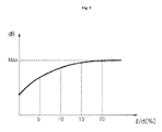
- the experimentation results as shown in FIG. 5 reveal that if the distance (1) increases, the amount of generated noise is increased, but if it is longer by a certain distance, specifically, larger than 20% of the diameter (d) of the hub shaft 120, noise caused by the generated circulation flow is not increased any more, whereas the length of the driving shaft 112 to be coupled with the hub shaft 120 is increased.
- the increase in the length of the driving shaft 112 increases vibration, improving the operation efficiency, but eccentricity of the driving shaft is also increased regardless of vortex, increasing noise due to the length of the driving shaft. Consequently, on balance, the distance (1) is preferably set within the range of 20% of the diameter (d) of the hub shaft.
Landscapes
- Engineering & Computer Science (AREA)
- Mechanical Engineering (AREA)
- General Engineering & Computer Science (AREA)
- Chemical & Material Sciences (AREA)
- Combustion & Propulsion (AREA)
- Structures Of Non-Positive Displacement Pumps (AREA)
- Other Air-Conditioning Systems (AREA)
Applications Claiming Priority (1)
| Application Number | Priority Date | Filing Date | Title |
|---|---|---|---|
| KR1020080009714A KR101546905B1 (ko) | 2008-01-30 | 2008-01-30 | 공기조화기용 실외기 |
Publications (3)
| Publication Number | Publication Date |
|---|---|
| EP2085618A2 true EP2085618A2 (de) | 2009-08-05 |
| EP2085618A3 EP2085618A3 (de) | 2011-10-12 |
| EP2085618B1 EP2085618B1 (de) | 2016-09-21 |
Family
ID=40638118
Family Applications (1)
| Application Number | Title | Priority Date | Filing Date |
|---|---|---|---|
| EP09151163.4A Not-in-force EP2085618B1 (de) | 2008-01-30 | 2009-01-23 | Außeneinheit einer Klimaanlage |
Country Status (5)
| Country | Link |
|---|---|
| US (1) | US8191381B2 (de) |
| EP (1) | EP2085618B1 (de) |
| KR (1) | KR101546905B1 (de) |
| CN (1) | CN101498313B (de) |
| ES (1) | ES2606343T3 (de) |
Cited By (1)
| Publication number | Priority date | Publication date | Assignee | Title |
|---|---|---|---|---|
| AT17059U1 (de) * | 2020-02-11 | 2021-04-15 | Thomas Euler Rolle | Axiallüfter |
Families Citing this family (6)
| Publication number | Priority date | Publication date | Assignee | Title |
|---|---|---|---|---|
| CN201531954U (zh) * | 2009-09-30 | 2010-07-21 | 中山大洋电机股份有限公司 | 一种热交换系统 |
| KR20110085646A (ko) * | 2010-01-21 | 2011-07-27 | 엘지전자 주식회사 | 송풍장치 및 이를 구비하는 실외기 |
| JP5240377B2 (ja) * | 2011-05-20 | 2013-07-17 | ダイキン工業株式会社 | 空気調和装置の室外機 |
| DE102012201883A1 (de) | 2012-02-09 | 2013-08-14 | BSH Bosch und Siemens Hausgeräte GmbH | Kältegerät mit einem Lüfter |
| MX346109B (es) | 2012-11-30 | 2017-03-07 | Plasticos Y Alambres S A De C V * | Guarda para aparatos de aire acondicionado. |
| JP2026047517A (ja) * | 2024-09-04 | 2026-03-16 | ニデック株式会社 | インペラ及びそれを備える送風装置 |
Family Cites Families (23)
| Publication number | Priority date | Publication date | Assignee | Title |
|---|---|---|---|---|
| JPS5844298A (ja) * | 1981-09-09 | 1983-03-15 | Matsushita Electric Ind Co Ltd | 送風装置 |
| JPS5844297A (ja) * | 1981-09-09 | 1983-03-15 | Matsushita Electric Ind Co Ltd | 送風装置 |
| US4943209A (en) * | 1988-07-11 | 1990-07-24 | Heil-Quaker Corporation | Hub for a plastic blower impeller |
| US4971520A (en) * | 1989-08-11 | 1990-11-20 | Airflow Research And Manufacturing Corporation | High efficiency fan |
| US5097678A (en) * | 1990-11-19 | 1992-03-24 | Aubuchon Steven L | Ventilating protective cover for top-discharge air conditioners |
| DE4143383C2 (de) * | 1991-07-03 | 1995-03-30 | Licentia Gmbh | Axialgebläse, insbesondere zur Kühlung eines dem Kühler eines Fahrzeugs vorgeordneten Kondensators einer Klimaanlage |
| US5895206A (en) * | 1997-05-30 | 1999-04-20 | Carrier Corporation | Fan and heat exchanger assembly |
| KR200258962Y1 (ko) | 1999-02-06 | 2002-01-04 | 유인만 | 송풍 팬 조립장치 |
| KR200233977Y1 (ko) | 2001-02-26 | 2001-09-26 | 이화케미칼 주식회사 | 에어콘용 팬 보스 |
| US6872048B2 (en) * | 2001-11-26 | 2005-03-29 | Lennox Industries, Inc. | Fan with reduced noise generation |
| WO2003085262A1 (en) * | 2002-03-30 | 2003-10-16 | University Of Central Florida | High efficiency air conditioner condenser fan |
| US7249931B2 (en) * | 2002-03-30 | 2007-07-31 | University Of Central Florida Research Foundation, Inc. | High efficiency air conditioner condenser fan with performance enhancements |
| US7191613B2 (en) * | 2002-05-08 | 2007-03-20 | Lg Electronics Inc. | Turbo fan and air conditioner having the same applied thereto |
| KR100614352B1 (ko) * | 2002-11-05 | 2006-08-21 | 다이킨 고교 가부시키가이샤 | 냉동 장치의 실외 유닛, 및 실외 유닛의 전장품 상자 |
| JP2004301451A (ja) * | 2003-03-31 | 2004-10-28 | Toshiba Kyaria Kk | 空気調和装置の室外機 |
| US7930897B2 (en) * | 2003-10-23 | 2011-04-26 | Lg Electronics Inc. | Window type air conditioner |
| KR101018925B1 (ko) * | 2004-03-19 | 2011-03-02 | 한라공조주식회사 | 축류팬 |
| KR20050099352A (ko) * | 2004-04-09 | 2005-10-13 | 엘지전자 주식회사 | 전면 흡토출 방식의 공기조화기용 실외기 |
| US7086825B2 (en) * | 2004-09-24 | 2006-08-08 | Carrier Corporation | Fan |
| CN1779272A (zh) * | 2004-11-18 | 2006-05-31 | 乐金电子(天津)电器有限公司 | 送风扇 |
| KR101155809B1 (ko) * | 2005-03-26 | 2012-06-12 | 한라공조주식회사 | 팬 및 쉬라우드 조립체 |
| US8038406B2 (en) * | 2006-08-25 | 2011-10-18 | Sanyo Electric Co., Ltd. | Axial fan and blade design method for the same |
| KR20080062891A (ko) * | 2006-12-29 | 2008-07-03 | 엘지전자 주식회사 | 공기조화기의 팬 |
-
2008
- 2008-01-30 KR KR1020080009714A patent/KR101546905B1/ko not_active Expired - Fee Related
-
2009
- 2009-01-23 ES ES09151163.4T patent/ES2606343T3/es active Active
- 2009-01-23 CN CN2009100025953A patent/CN101498313B/zh not_active Expired - Fee Related
- 2009-01-23 EP EP09151163.4A patent/EP2085618B1/de not_active Not-in-force
- 2009-01-28 US US12/361,088 patent/US8191381B2/en not_active Expired - Fee Related
Cited By (3)
| Publication number | Priority date | Publication date | Assignee | Title |
|---|---|---|---|---|
| AT17059U1 (de) * | 2020-02-11 | 2021-04-15 | Thomas Euler Rolle | Axiallüfter |
| WO2021159161A1 (de) | 2020-02-11 | 2021-08-19 | Euler Rolle Thomas | Axiallüfter mit öffnungen in der nabe |
| US12012970B2 (en) | 2020-02-11 | 2024-06-18 | Thomas Euler-Rolle | Axial fan with openings in the hub |
Also Published As
| Publication number | Publication date |
|---|---|
| EP2085618A3 (de) | 2011-10-12 |
| EP2085618B1 (de) | 2016-09-21 |
| CN101498313A (zh) | 2009-08-05 |
| KR20090083738A (ko) | 2009-08-04 |
| KR101546905B1 (ko) | 2015-08-24 |
| US20090188274A1 (en) | 2009-07-30 |
| ES2606343T3 (es) | 2017-03-23 |
| US8191381B2 (en) | 2012-06-05 |
| CN101498313B (zh) | 2013-06-19 |
Similar Documents
| Publication | Publication Date | Title |
|---|---|---|
| EP2085618A2 (de) | Außeneinheit einer Klimaanlage und Lüfter dafür | |
| US20090113915A1 (en) | Air conditioner | |
| CN222256822U (zh) | 一种顶出风式空调室外机 | |
| CN219693459U (zh) | 窗式空调器 | |
| CN219624176U (zh) | 空调室外机 | |
| EP3385627A1 (de) | Ausseneinheit | |
| CN222417727U (zh) | 挂式空调 | |
| KR101387716B1 (ko) | 공기조화기용 실외기 | |
| JP2003240278A (ja) | 移動自在な小型の空気調和機 | |
| KR101476294B1 (ko) | 공기조화기용 실외기 팬 | |
| CN214249884U (zh) | 空调器 | |
| CN223985271U (zh) | 空调器 | |
| CN223564330U (zh) | 空调室内机及空调器 | |
| CN220648590U (zh) | 一种高连接强度的热泵外机 | |
| CN219550672U (zh) | 空调器 | |
| CN220397693U (zh) | 一种液冷散热的空调外机 | |
| CN216976927U (zh) | 空调内机及空调 | |
| CN218763910U (zh) | 空调器 | |
| CN223782960U (zh) | 移动空调 | |
| CN220892415U (zh) | 一种空调室外机及空调器 | |
| CN218379634U (zh) | 一种空调器 | |
| KR102521853B1 (ko) | 공기조화기 | |
| CN100513917C (zh) | 空气调节器 | |
| KR20130067936A (ko) | 공기조화기 | |
| KR100597954B1 (ko) | 에어컨 실내기의 토출구 이중 차단구조 |
Legal Events
| Date | Code | Title | Description |
|---|---|---|---|
| PUAI | Public reference made under article 153(3) epc to a published international application that has entered the european phase |
Free format text: ORIGINAL CODE: 0009012 |
|
| AK | Designated contracting states |
Kind code of ref document: A2 Designated state(s): AT BE BG CH CY CZ DE DK EE ES FI FR GB GR HR HU IE IS IT LI LT LU LV MC MK MT NL NO PL PT RO SE SI SK TR |
|
| AX | Request for extension of the european patent |
Extension state: AL BA RS |
|
| REG | Reference to a national code |
Ref country code: DE Ref legal event code: R079 Free format text: PREVIOUS MAIN CLASS: F04D0025080000 Ipc: F04D0029260000 |
|
| RIC1 | Information provided on ipc code assigned before grant |
Ipc: F04D 29/32 20060101ALI20110517BHEP Ipc: F24F 1/00 20110101ALI20110517BHEP Ipc: F04D 29/64 20060101ALI20110517BHEP Ipc: F04D 29/26 20060101AFI20110517BHEP |
|
| PUAL | Search report despatched |
Free format text: ORIGINAL CODE: 0009013 |
|
| AK | Designated contracting states |
Kind code of ref document: A3 Designated state(s): AT BE BG CH CY CZ DE DK EE ES FI FR GB GR HR HU IE IS IT LI LT LU LV MC MK MT NL NO PL PT RO SE SI SK TR |
|
| AX | Request for extension of the european patent |
Extension state: AL BA RS |
|
| RIC1 | Information provided on ipc code assigned before grant |
Ipc: F04D 29/32 20060101ALI20110907BHEP Ipc: F04D 29/26 20060101AFI20110907BHEP Ipc: F04D 29/64 20060101ALI20110907BHEP Ipc: F24F 1/00 20110101ALI20110907BHEP |
|
| 17P | Request for examination filed |
Effective date: 20120330 |
|
| AKX | Designation fees paid |
Designated state(s): ES FR GB IT |
|
| REG | Reference to a national code |
Ref country code: DE Ref legal event code: R108 |
|
| REG | Reference to a national code |
Ref country code: DE Ref legal event code: R108 Effective date: 20120620 |
|
| 17Q | First examination report despatched |
Effective date: 20140806 |
|
| GRAP | Despatch of communication of intention to grant a patent |
Free format text: ORIGINAL CODE: EPIDOSNIGR1 |
|
| INTG | Intention to grant announced |
Effective date: 20160119 |
|
| RAP1 | Party data changed (applicant data changed or rights of an application transferred) |
Owner name: LG ELECTRONICS INC. |
|
| GRAR | Information related to intention to grant a patent recorded |
Free format text: ORIGINAL CODE: EPIDOSNIGR71 |
|
| GRAS | Grant fee paid |
Free format text: ORIGINAL CODE: EPIDOSNIGR3 |
|
| GRAA | (expected) grant |
Free format text: ORIGINAL CODE: 0009210 |
|
| INTC | Intention to grant announced (deleted) | ||
| INTG | Intention to grant announced |
Effective date: 20160810 |
|
| AK | Designated contracting states |
Kind code of ref document: B1 Designated state(s): ES FR GB IT |
|
| REG | Reference to a national code |
Ref country code: GB Ref legal event code: FG4D |
|
| REG | Reference to a national code |
Ref country code: FR Ref legal event code: PLFP Year of fee payment: 9 |
|
| PLBE | No opposition filed within time limit |
Free format text: ORIGINAL CODE: 0009261 |
|
| STAA | Information on the status of an ep patent application or granted ep patent |
Free format text: STATUS: NO OPPOSITION FILED WITHIN TIME LIMIT |
|
| 26N | No opposition filed |
Effective date: 20170622 |
|
| GBPC | Gb: european patent ceased through non-payment of renewal fee |
Effective date: 20170123 |
|
| PG25 | Lapsed in a contracting state [announced via postgrant information from national office to epo] |
Ref country code: GB Free format text: LAPSE BECAUSE OF NON-PAYMENT OF DUE FEES Effective date: 20170123 |
|
| REG | Reference to a national code |
Ref country code: FR Ref legal event code: PLFP Year of fee payment: 10 |
|
| PGFP | Annual fee paid to national office [announced via postgrant information from national office to epo] |
Ref country code: ES Payment date: 20190212 Year of fee payment: 11 Ref country code: IT Payment date: 20190114 Year of fee payment: 11 |
|
| PGFP | Annual fee paid to national office [announced via postgrant information from national office to epo] |
Ref country code: FR Payment date: 20191209 Year of fee payment: 12 |
|
| PG25 | Lapsed in a contracting state [announced via postgrant information from national office to epo] |
Ref country code: IT Free format text: LAPSE BECAUSE OF NON-PAYMENT OF DUE FEES Effective date: 20200123 |
|
| REG | Reference to a national code |
Ref country code: ES Ref legal event code: FD2A Effective date: 20210604 |
|
| PG25 | Lapsed in a contracting state [announced via postgrant information from national office to epo] |
Ref country code: ES Free format text: LAPSE BECAUSE OF NON-PAYMENT OF DUE FEES Effective date: 20200124 |
|
| PG25 | Lapsed in a contracting state [announced via postgrant information from national office to epo] |
Ref country code: FR Free format text: LAPSE BECAUSE OF NON-PAYMENT OF DUE FEES Effective date: 20210131 |