EP2085653B1 - Dispositif à transmission variable en continu doté d'un train de poulies de transmission de décalage faible - Google Patents
Dispositif à transmission variable en continu doté d'un train de poulies de transmission de décalage faible Download PDFInfo
- Publication number
- EP2085653B1 EP2085653B1 EP09250264.0A EP09250264A EP2085653B1 EP 2085653 B1 EP2085653 B1 EP 2085653B1 EP 09250264 A EP09250264 A EP 09250264A EP 2085653 B1 EP2085653 B1 EP 2085653B1
- Authority
- EP
- European Patent Office
- Prior art keywords
- pulley
- transmission device
- transmission
- low shift
- train
- Prior art date
- Legal status (The legal status is an assumption and is not a legal conclusion. Google has not performed a legal analysis and makes no representation as to the accuracy of the status listed.)
- Not-in-force
Links
Images

Classifications
-
- F—MECHANICAL ENGINEERING; LIGHTING; HEATING; WEAPONS; BLASTING
- F16—ENGINEERING ELEMENTS AND UNITS; GENERAL MEASURES FOR PRODUCING AND MAINTAINING EFFECTIVE FUNCTIONING OF MACHINES OR INSTALLATIONS; THERMAL INSULATION IN GENERAL
- F16H—GEARING
- F16H37/00—Combinations of mechanical gearings, not provided for in groups F16H1/00 - F16H35/00
- F16H37/02—Combinations of mechanical gearings, not provided for in groups F16H1/00 - F16H35/00 comprising essentially only toothed or friction gearings
-
- F—MECHANICAL ENGINEERING; LIGHTING; HEATING; WEAPONS; BLASTING
- F16—ENGINEERING ELEMENTS AND UNITS; GENERAL MEASURES FOR PRODUCING AND MAINTAINING EFFECTIVE FUNCTIONING OF MACHINES OR INSTALLATIONS; THERMAL INSULATION IN GENERAL
- F16H—GEARING
- F16H9/00—Gearings for conveying rotary motion with variable gear ratio, or for reversing rotary motion, by endless flexible members
- F16H9/02—Gearings for conveying rotary motion with variable gear ratio, or for reversing rotary motion, by endless flexible members without members having orbital motion
- F16H9/04—Gearings for conveying rotary motion with variable gear ratio, or for reversing rotary motion, by endless flexible members without members having orbital motion using belts, V-belts, or ropes
- F16H9/12—Gearings for conveying rotary motion with variable gear ratio, or for reversing rotary motion, by endless flexible members without members having orbital motion using belts, V-belts, or ropes engaging a pulley built-up out of relatively axially-adjustable parts in which the belt engages the opposite flanges of the pulley directly without interposed belt-supporting members
- F16H9/16—Gearings for conveying rotary motion with variable gear ratio, or for reversing rotary motion, by endless flexible members without members having orbital motion using belts, V-belts, or ropes engaging a pulley built-up out of relatively axially-adjustable parts in which the belt engages the opposite flanges of the pulley directly without interposed belt-supporting members using two pulleys, both built-up out of adjustable conical parts
- F16H2009/166—Arrangements of two or more belt gearings mounted in series, e.g. for increasing ratio coverage
Definitions
- variable spacing transmission V-belt grooves of driving and driven pulleys is modulated, whereby the operative belt transmission radial distance of driving pulley or driven pulley is changed to further change the transmission speed ratio between the driving pulley and the driven pulley;
- the above said spacing modulation for variable spacing transmission V-belt grooves of driving or driven pulleys of the continuous variable transmission device is required to be driven by one or more than one kinds of axial driving forces including:
- the above said 1 ⁇ 5 methods are passive operations of continuous variable transmission function.
- Types of conventional continuous variable transmission devices of different input and output shafts structures are numerous including: rubber belt type, metal belt type, chain type, or electronic (ECVT) type, friction disk type or known continuous variable transmission device of different shafts type, etc.
- ECVT electronic
- US 3926020 discloses an automatic transmission for vehicles in which the speed ratio of the transmission is automatically adjusted in response to a control signal which is generated as a function of the speed of the drive system of the vehicle.
- the continuous variable transmission device with low shift transmission pulley train is passively operated by an axial driving force generated by operating torque by axially pre-pressed springs on the driven pulleys, thereby to modulate and operate the speed ratio of the continuous variable transmission thereof.
- continuous variable transmission devices of different shafts type is advantageous in convenient operation for its automatic speed ratio adjustment function according to the rotational speed change of the driving pulley input shaft and the size of loading torque at loading side
- said continuous variable transmission device of different shafts type has the imperfections:
- the invented continuous variable transmission device with low shift transmission pulley train is innovatingly disclosed by the features of claim 1.
- the continuous variable transmission device with low shift transmission pulley train is passively operated by an axial driving force generated by operating torque to execute axial drive to the driven pulley and further provided with axially pre-pressed springs to constitute the continuous variable transmission function; and further referring to input preset operating modes, detected speeds and torques, etc. thereby to modulate and operate the speed ratio of the continuous variable transmission thereof.
- the continuous variable transmission device of different shafts type is advantageous in convenient operation for its automatic speed ratio adjustment function according to the rotational speed change of the driving pulley input shaft and the size of the loading torque at loading side, said continuous variable transmission device of different shafts type has the imperfections:
- the invented continuous variable transmission device with low shift transmission pulley train is innovatingly disclosed by the features of claim 1.
- the continuous variable transmission device with low shift transmission pulley train is constituted by the following:
- the low shift transmission pulley train 102 is constituted by the following:
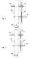
- the continuous variable transmission device with low shift transmission pulley train constituted by above said main structures includes that an input shaft 101 of the continuous variable transmission device of different shafts type 100 is additionally installed with a driving pulley of low shift transmission pulley train 102, and an unidirectional transmission device 111 is further installed between the two.
- Transmission direction of said unidirectional transmission device 111 shall allow said continuous variable transmission device of low shift transmission pulley train 102 to provide that: during higher load operation, if a decelerating type continuous variable transmission device is adopted by the continuous variable transmission device of differnet shafts type 100 to operate in a maximum deceleration speed ratio or a near maximum deceleration speed ratio status, or if an accelerating type continuous variable transmission device is adopted to operate in a minimum acceleration speed ratio or a near minimum deceleration speed ratio status, thereby to make the rotational speed of the driving pulley of low shift transmission pulley train 102 lower than that of the input shaft 101 in the same revolving direction, then the revolving kinetic energy of the input shaft 101 is transmitted through the unidirectional tansmission device 111 and the low shift transmission pulley train 102 to drive the output shaft 103 and further to drive the load.
- the power originally transmitted directly through said continuous variable transmission device of different shafts type 100 is changed to be transmitted through said low shift transmission pulley train 102 to further drive the output shaft 103.
- the power is directly transmitted through said continuous variable transmission device of different shafts type 100 to drive the output shaft 103;
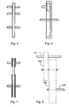
- an unidirectional transmission device 111 is selected to be installed between the driven pulley of low shift transmission pulley train 102 and the output shaft 103, then during higher load operation, if a decelerating type continuous variable transmission device is adopted by the continuous variable transmission device of differnet shafts type 100 to operate in a maximum deceleration speed ratio or a near maximum deceleration speed ratio status, or if an accelerating type continuous variable transmission device is adopted to operate in a minimum acceleration speed ratio or a near minimum deceleration speed ratio status, thereby to make rotational speed of the driven pulley of low shift transmission pulley train 102 higher than that of the output shaft 103 in the same revolving direction, then the revolving kinetic energy is transmitted through the low shift transmission pulley train 102 and the unidirectional tansmission device 111 to drive the output shaft 103 and further to drive the load.
- the power originally transmitted directly through said continuous variable transmission device of different shafts type 100 is changed to be transmitted through said low shift transmission pulley train 102 to further drive the output shaft 103.
- the power is directly transmitted through said continuous variable transmission device of different shafts type 100 to drive the output shaft 103.
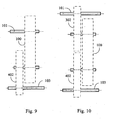
- a middle transmission pulley for accelerating speed ratio or decelerating speed ratio can be installed to satisfy the needs for accelerating speed ratio or decelerating speed ratio in order to ensure a better transmission efficiency, wherein said middle transmission pulley includes:
- the low shift transmission pulley train of said continuous variable transmission device with low shift transmission pulley train can be selected according to application requirements to include the following:
- input methods for supplying revolving kinetic energy to the input shaft 101 can be selected based on application requirements to include the following:
- the revolving kinetic energy output from the output shaft 103 of said continuous variable transmission of low shift transmission pulley train can be selected according to application requirements to include the following:
- the practical applied structures of said continuous variable transmission device of different shafts type 100 and said low shift transmission pulley train 102 can be selectively made to independently separated mechanical devices and combined afterwards for transmission or made to an integral structure or made to a structure of a common integrated mechanical device and a common integrated casing.
- said continuous variable transmission device with low shift transmission pulley train is characterized in that during high load operation, the kinetic energy is transmitted through said low shift transmission pulley train 102 to drive the output shaft 103 and to further drive the load, thereby to extend the service life of said continuous transmission device and to promote its loading efficiency.
- a continuous variable transmission device with low shift transmission pulley train is innovatingly disclosed by that a low shift transmission pulley train with fixed speed ratio and attached unidirectional transmission device in the same revolving direction are installed between the input shaft and output shaft of a continuous variable transmission device, wherein if a decelerating type continuous variable transmission device is used to operated at maximum decelerating speed ratio or near maximum decelerating speed ratio status, or an accelerating type continuous variable transmission device is used to operate at minimum accelerating speed ratio or near minimum accelerating speed ratio status, then during high load operation, when the driving pulley rotational speed of low shift transmission pulley train is lower than that of the input shaft in the same revolving direction, the revolving kinetic energy of the input shaft is transmitted through the unidirectional transmission device and the low shift transmission pulley train to drive the output shaft and further to drive the load; at said status, the power originally transmitted through the continuous variable transmission device of different shafts type is changed to be transmitted through the low shift transmission pulley train.
- a continuous variable transmission device of different input and output shafts structure comprises at least one kind of rubber belt type, metal belt type, chain type, or electronic (ECVT) type, friction disk type continuous variable transmission devices, wherein transmission speed ratio thereof can be either passively automatically modulated by following torque or following rotational speed; or actively modulated by applying a linear driving force either generated by an externally powered linear driving device or by a revolving driving device via mechanical transmission for conversion to change spacing between the transmission V-belt grooves of both or either of driving and driven pulleys.
- ECVT electronic
- an input shaft (101) is arranged to receive a revolving kinetic energy input, whereby said revolving kinetic energy is transmitted to the driving pulley of the continuous variable transmission device of different shafts type (100) and to the input end of the unidirectional transmission device (111).
- an output shaft (103) is arranged to provide revolving kinetic energy output for driving the load, whereby the revolving kinetic energy from driven pulley of the continuous variable transmission device of different shafts type (100) or from the driven pulley of low shift transmission pulley train (102) is transmitted by it to the load.
- a unidirectional transmission device (111) is constituted by an unidirectional transmission device in radial direction type or an unidirectional transmission device in axial direction type, including the constitution by an unidirectional bearing with unidirectional transmission function, an unidirectional clutch or an unidirectional transmission mechanism or device, wherein said unidirectional transmission device (111) can be optionally installed as needed between the input shaft (101) and the driving pulley of low shift transmission pulley train (102), or installed as needed between the driven pulley of the low shift transmission pulley train (102) and the output shaft (103).
- the transmission direction of the unidirectional transmission device (111) is that when rotational speed of the input shaft (101) is higher than that of the driving pulley of the low shift transmission pulley train (102) in the same revolving direction, the revolving kinetic energy is transmitted to the driving pulley of the low shift transmission pulley train (102); on the contrary, if it is not so, the revolving kinetic energy from the input shaft (101) is not transmitted to the driving pulley of low shift transmission pulley train (102).
- the low shift transmission pulley train (102) comprises a driving pulley which is driven by the input shaft (101) and a driven pulley for driving the output shaft (103), wherein said driving pulley and driven pulley are transmitted in the same revolving direction, the transmission speed ratio thereof appears a low shift transmission in decelerating transmission relative to the continuous variable transmission device of different shafts type (100), and the speed ratio relationship between the low shift transmission pulley train (102) and the continuous variable transmission device of different shafts type (100) is:
- the low shift transmission pulley train (102) is constituted by the following:
- the input methods for supplying revolving kinetic energy to the input shaft (101) may be selected based on application requirements to include one or more than one following inputting methods:
- the revolving kinetic energy output from the output shaft (103) may be selected according to application requirements to include one or more than one outputting methods as following:
- the practical applied structures of said continuous variable transmission device of different shafts type (100) and said low shift transmission pulley train (102) can be selectively made to independently separated mechanical devices and combined afterwards for transmission or made to an integral structure or made to a structure of a common integrated mechanical device and a common integrated casing.
Landscapes
- Engineering & Computer Science (AREA)
- General Engineering & Computer Science (AREA)
- Mechanical Engineering (AREA)
- Transmission Devices (AREA)
- Transmissions By Endless Flexible Members (AREA)
- Arrangement And Driving Of Transmission Devices (AREA)
Claims (12)
- Dispositif de transmission, ayant un arbre d'entrée (101) et un arbre de sortie (103), le dispositif comprenant :un dispositif de transmission à variation continue (100) ;un train de poulies de transmission à rapport de vitesse fixe de décalage faible (102) ayant une poulie d'entraînement et une poulie entraînée ; etun dispositif de transmission unidirectionnelle (111), agencé pour tourner dans le même sens que l'une des poulies du train de poulies (102) ;le train de poulies de transmission à rapport de vitesse fixe de décalage faible (102) et le dispositif de transmission unidirectionnelle (111) étant installés entre l'arbre d'entrée (101) et l'arbre de sortie (103) ; etle dispositif de transmission à variation continue étant installé entre l'arbre d'entrée (101) et l'arbre de sortie (103) de façon à transmettre de la puissance directement de l'arbre d'entrée (101) à l'arbre de sortie (103) et comportant des ressorts axialement pré-contraints au niveau d'une poulie entraînée pour constituer la fonction de transmission à variation continue ;le rapport de vitesse de transmission du dispositif de transmission à variation continue (100) étant automatiquement modulé de façon passive par un couple de suivi de telle sorte que, lors de l'entraînement de l'arbre de sortie au moyen du dispositif de transmission à variation continue (100) et lorsque la charge devient un fonctionnement à charge élevée, et lorsque la vitesse de rotation de la poulie d'entraînement du train de poulies de transmission à rapport de vitesse fixe de décalage faible (102) est inférieure à celle de l'arbre d'entrée (101), l'énergie cinétique de rotation de l'arbre d'entrée (101) est transmise au moyen du dispositif de transmission unidirectionnelle (111) et du train de poulies de transmission à rapport de vitesse fixe de décalage faible (102) pour entraîner l'arbre de sortie (103) ainsi que pour entraîner une charge.
- Dispositif de transmission selon la revendication 1, comprenant en outre au moins un disque de friction, le disque de friction étant un ou plusieurs des types suivants : du type courroie en caoutchouc, du type courroie métallique, du type chaîne et du type électronique (ECVT).
- Dispositif de transmission selon l'une quelconque des revendications précédentes, dans lequel l'arbre d'entrée est agencé pour recevoir une entrée d'énergie cinétique, ladite énergie cinétique étant transmise à une poulie d'entraînement du dispositif de transmission à variation continue (100) et à une extrémité d'entrée du dispositif de transmission unidirectionnelle (111).
- Dispositif de transmission selon l'une quelconque des revendications précédentes, dans lequel l'arbre de sortie est agencé pour fournir une sortie d'énergie cinétique pour entraîner la charge, l'énergie cinétique provenant d'une poulie entraînée du dispositif de transmission à variation continue (100), ou d'une poulie entraînée du train de poulies de transmission de décalage faible (102), étant transmise par l'arbre de sortie à la charge.
- Dispositif de transmission selon l'une quelconque des revendications précédentes, dans lequel le dispositif de transmission unidirectionnelle (111) est du type à direction radiale ou du type à direction axiale et comprend un palier unidirectionnel ayant une fonction de transmission unidirectionnelle, un embrayage unidirectionnel ou un mécanisme de transmission unidirectionnelle, ledit dispositif de transmission unidirectionnelle (111) étant installé entre l'arbre d'entrée (101) et la poulie d'entraînement du train de poulies de transmission de décalage faible (102), ou entre la poulie entraînée du train de poulies de transmission de décalage faible (102) et l'arbre de sortie (103).
- Dispositif de transmission selon l'une quelconque des revendications précédentes, dans lequel, lorsque la vitesse de rotation de l'arbre d'entrée (101) est supérieure à celle de la poulie d'entraînement du train de poulies de transmission de décalage faible (102) dans le même sens de rotation, l'énergie cinétique de rotation est transmise à la poulie d'entraînement du train de poulies de transmission de décalage faible (102) et, lorsque la vitesse de rotation n'est pas supérieure à celle de la poulie d'entraînement du train de poulies de transmission de décalage faible, l'énergie cinétique de rotation provenant de l'arbre d'entrée (101) n'est pas transmise à la poulie d'entraînement du train de poulies de transmission de décalage faible (102).
- Dispositif de transmission selon l'une quelconque des revendications précédentes, dans lequel le train de poulies de transmission de décalage faible (102) comprend une poulie d'entraînement qui est entraînée par l'arbre d'entrée (101) et une poulie entraînée pour entraîner l'arbre de sortie (103), ladite poulie d'entraînement et ladite poulie entraînée étant transmises dans le même sens de rotation ; et le rapport de vitesse de transmission de celui-ci faisant apparaître une transmission de décalage faible dans une transmission de décélération par rapport au dispositif de transmission à variation continue du type à arbres différents (100), et la relation de rapport de vitesse entre le train de poulies de transmission de décalage faible (102) et le dispositif de transmission à variation continue du type à arbres différents (100) étant :1) Rapport de vitesse de la poulie d'entraînement pour entraîner la poulie entraînée du train de poulies de transmission de décalage faible (102) ≤ rapport de vitesse du dispositif de transmission à variation continue du type à arbres différents (100) en sortie de vitesse faible ;2) Rapport de vitesse du dispositif de transmission à variation continue du type à arbres différents (100) en sortie de vitesse faible < Rapport de vitesse de la poulie d'entraînement pour entraîner la poulie entraînée du train de poulies de transmission de décalage faible (102) < rapport de vitesse du dispositif de transmission à variation continue du type à arbres différents (100) en sortie de vitesse élevée.
- Dispositif de transmission selon l'une quelconque des revendications précédentes, dans lequel le train de poulies de transmission de décalage faible (102) comprend un ou plusieurs de ce qui suit :- une poulie à chaîne d'entraînement, une poulie à chaîne entraînée et une chaîne de transmission montée ;- une poulie d'entraînement, une poulie entraînée centrale et une poulie entraînée, lesdites poulie d'entraînement, poulie entraînée centrale et poulie entraînée comprenant des structures par engrenages ou poulies à friction ;- un train d'engrenages à engrènement intérieur ou un train de poulies à friction intérieure comprenant une poulie de transmission de diamètre extérieur plus petit et une poulie de transmission par l'intérieur de diamètre extérieur plus grand ; et- une poulie à courroie d'entraînement, une poulie à courroie entraînée et une courroie de transmission montée, telle qu'une courroie en toile, une courroie en acier ou une courroie articulée.
- Dispositif de transmission avec train de poulies de transmission de décalage faible selon l'une quelconque des revendications précédentes, comprenant un arbre d'entrée (101) du dispositif de transmission à variation continue du type à arbres différents (100) qui est de plus installé avec une poulie d'entraînement du train de poulies de transmission de décalage faible (102), et un dispositif de transmission unidirectionnelle (111) est en outre installé entre les deux ; le sens de transmission dudit dispositif de transmission unidirectionnelle (111) doit permettre audit dispositif de transmission à variation continue du train de poulies de transmission de décalage faible (102) de garantir que : pendant un fonctionnement à charge plus élevée, si un dispositif de transmission à variation continue du type à décélération est adopté par le dispositif de transmission à variation continue du type à arbres différents (100) pour fonctionner avec un rapport de vitesse de décélération maximal ou un état de rapport de vitesse de décélération presque maximal, ou si un dispositif de transmission à variation continue du type à accélération est adopté pour fonctionner avec un rapport de vitesse d'accélération minimal ou un état de rapport de vitesse de décélération presque minimal, pour ainsi amener la vitesse de rotation de la poulie d'entraînement du train de poulies de transmission de décalage faible (102) à être inférieure à celle de l'arbre d'entrée (101) dans le même sens de rotation, puis l'énergie cinétique de rotation de l'arbre d'entrée (101) est transmise au moyen du dispositif de transmission unidirectionnelle (111) et du train de poulies de transmission de décalage faible (102) pour entraîner l'arbre de sortie (103) ainsi que pour entraîner la charge ; dans ledit état, la puissance transmise à l'origine directement au moyen dudit dispositif de transmission à variation continue du type à arbres différents (100) est changée pour être transmise au moyen dudit train de poulies de transmission de décalage faible (102) pour entraîner en outre l'arbre de sortie (103) ; pendant un fonctionnement à charge plus faible, la puissance est directement transmise au moyen dudit dispositif de transmission à variation continue du type à arbres différents (100) pour entraîner l'arbre de sortie (103).
- Dispositif de transmission avec train de poulies de transmission de décalage faible selon l'une quelconque des revendications précédentes, dans lequel, si un dispositif de transmission unidirectionnelle (111) est choisi pour être installé entre la poulie entraînée du train de poulies de transmission de décalage faible (102) et l'arbre de sortie (103), alors pendant un fonctionnement à charge plus élevée, si un dispositif de transmission à variation continue du type à décélération est adopté par le dispositif de transmission à variation continue du type à arbres différents (100) pour fonctionner avec un rapport de vitesse de décélération maximal ou un état de rapport de vitesse de décélération presque maximal, ou si un dispositif de transmission à variation continue du type à accélération est adopté pour fonctionner avec un rapport de vitesse d'accélération minimal ou un état de rapport de vitesse de décélération presque minimal, pour ainsi amener la vitesse de rotation de la poulie entraînée du train de poulies de transmission de décalage faible (102) à être supérieure à celle de l'arbre de sortie (103) dans le même sens de rotation, ensuite l'énergie cinétique de rotation est transmise au moyen du train de poulies de transmission de décalage faible (102) et du dispositif de transmission unidirectionnelle (111) pour entraîner l'arbre de sortie (103) ainsi que pour entraîner la charge ; dans ledit état, la puissance transmise à l'origine directement au moyen dudit dispositif de transmission à variation continue du type à arbres différents (100) est changée pour être transmise au moyen dudit train de poulies de transmission de décalage faible (102) pour entraîner en outre l'arbre de sortie (103) ; pendant un fonctionnement à charge plus faible, la puissance est directement transmise au moyen dudit dispositif de transmission à variation continue du type à arbres différents (100) pour entraîner l'arbre de sortie (103).
- Dispositif de transmission avec train de poulies de transmission de décalage faible selon l'une quelconque des revendications précédentes, dans lequel, dans un souci d'efficacité, lorsque les diamètres de la poulie d'entraînement et de la poulie entraînée dans le dispositif de transmission à variation continue du type à arbres différents (100) dudit dispositif de transmission à variation continue avec train de poulies de transmission de décalage faible sont plus similaires l'un à l'autre pour garantir une meilleure efficacité, une poulie de transmission centrale pour rapport de vitesse d'accélération ou rapport de vitesse de décélération peut être installée pour satisfaire les besoins pour un rapport de vitesse d'accélération ou un rapport de vitesse de décélération afin de garantir une meilleure efficacité de transmission, ladite poulie de transmission centrale comprenant :1) Un train de poulies de changement de vitesse (302) est en outre installé entre l'arbre d'entrée (101) et la poulie d'entraînement du dispositif de transmission à variation continue du type à arbres différents (100) pour changer le rapport de vitesse total de l'arbre d'entrée (101) et de l'arbre de sortie (103), et correspond au sens de rotation requis ;2) Un train de poulies de changement de vitesse (402) est en outre installé entre l'arbre de sortie (103) et la poulie entraînée du dispositif de transmission à variation continue du type à arbres différents (100) pour changer le rapport de vitesse total de l'arbre d'entrée (101) et de l'arbre de sortie (103), et correspond au sens de rotation requis ;3) Les trains de poulies de changement de vitesse (302, 402) sont installés simultanément entre l'arbre d'entrée (101) et la poulie d'entraînement du dispositif de transmission à variation continue du type à arbres différents (100) et entre l'arbre de sortie (103) et la poulie entraînée du dispositif de transmission à variation continue du type à arbres différents (100) pour changer le rapport de vitesse total de l'arbre d'entrée (101), par l'intermédiaire du dispositif de transmission à variation continue du type à arbres différents (100), à l'arbre de sortie (103), et correspondent au sens de rotation requis.
- Dispositif de transmission avec train de poulies de transmission de décalage faible selon l'une quelconque des revendications précédentes, dans lequel le train de poulies de transmission de décalage faible peut être choisi selon les exigences d'application pour comprendre un ou plusieurs des méthodes de constitution suivantes :1) Constitution par un train de poulies de transmission de décalage faible, à étage unique, de rapport de vitesse fixe ;2) Constitution par un train de poulies de transmission variable de décalage faible, du type à étages multiples, de sélection manuelle ou de transmission automatique.
Applications Claiming Priority (1)
| Application Number | Priority Date | Filing Date | Title |
|---|---|---|---|
| US682908P | 2008-02-01 | 2008-02-01 |
Publications (3)
| Publication Number | Publication Date |
|---|---|
| EP2085653A2 EP2085653A2 (fr) | 2009-08-05 |
| EP2085653A3 EP2085653A3 (fr) | 2010-10-06 |
| EP2085653B1 true EP2085653B1 (fr) | 2015-03-11 |
Family
ID=40521636
Family Applications (1)
| Application Number | Title | Priority Date | Filing Date |
|---|---|---|---|
| EP09250264.0A Not-in-force EP2085653B1 (fr) | 2008-02-01 | 2009-01-30 | Dispositif à transmission variable en continu doté d'un train de poulies de transmission de décalage faible |
Country Status (6)
| Country | Link |
|---|---|
| US (1) | US8226506B2 (fr) |
| EP (1) | EP2085653B1 (fr) |
| JP (1) | JP5971885B2 (fr) |
| CN (2) | CN101498357B (fr) |
| ES (1) | ES2536879T3 (fr) |
| TW (1) | TWI463084B (fr) |
Families Citing this family (9)
| Publication number | Priority date | Publication date | Assignee | Title |
|---|---|---|---|---|
| US7643928B2 (en) * | 2004-01-05 | 2010-01-05 | Bombardier Transportation Gmbh | System and method for controlling the speed of a gas turbine engine |
| TWI463084B (zh) * | 2008-02-01 | 2014-12-01 | Tai Her Yang | 具低檔傳動輪組之無段變速傳動裝置 |
| US9169909B2 (en) * | 2009-11-24 | 2015-10-27 | Tai-Her Yang | Stepless variable transmission device with parallel low gear wheel group |
| CN102506141A (zh) * | 2010-01-02 | 2012-06-20 | 沈维聪 | 低速逆转同步器 |
| US8104560B1 (en) * | 2010-11-12 | 2012-01-31 | Ting-Jung Tseng | Driving device utilizing inertia |
| CN106800069A (zh) * | 2015-11-25 | 2017-06-06 | 徐夫子 | 电力辅助自行车的无段变速装置 |
| CN106644108A (zh) * | 2017-01-24 | 2017-05-10 | 莱茵技术监督服务(广东)有限公司 | 用于搅拌机温升测试的可调式负载装置 |
| CN109149861B (zh) * | 2018-08-30 | 2025-02-25 | 宁波博生机电科技有限公司 | 一种船用主轴驱动恒速发电装置 |
| CN111483772B (zh) * | 2020-04-17 | 2021-07-09 | 聊城开发区隆阳机械制造有限责任公司 | 一种工厂流水线专用自动限速设备 |
Citations (2)
| Publication number | Priority date | Publication date | Assignee | Title |
|---|---|---|---|---|
| CH470607A (de) * | 1965-08-10 | 1969-03-31 | Ambros Richard | Die Drehmomentübertragung selbstregelnder Umschlingungstrieb |
| GB2004604A (en) * | 1977-09-16 | 1979-04-04 | Int Harvester Co | Variable diameter torque sensing drive for harvesting combine |
Family Cites Families (10)
| Publication number | Priority date | Publication date | Assignee | Title |
|---|---|---|---|---|
| US3926020A (en) * | 1974-01-09 | 1975-12-16 | Philip Dantowitz | Vehicle automatic transmission bicycle with alternate fixed ratio or variable ratio speed sensitive power paths |
| FR2420062A1 (fr) * | 1978-03-16 | 1979-10-12 | Renault | Transmission a variateur |
| IT1159899B (it) * | 1978-07-13 | 1987-03-04 | Fiat Spa | Gruppo di trasmissione per veicoli a motore |
| JPS60249758A (ja) * | 1984-05-25 | 1985-12-10 | Nissan Motor Co Ltd | 無段変速機 |
| JPH0680340B2 (ja) * | 1984-10-15 | 1994-10-12 | スズキ株式会社 | Vベルト式自動変速機 |
| DE3872035T2 (de) * | 1987-04-24 | 1992-12-03 | Honda Motor Co Ltd | Stufenlos verstellbares riemengetriebe fuer kraftfahrzeuge. |
| JPS63195150U (fr) * | 1987-06-05 | 1988-12-15 | ||
| JP2743379B2 (ja) * | 1988-05-06 | 1998-04-22 | 日産自動車株式会社 | 変速機の油圧制御装置 |
| US7803075B2 (en) * | 2006-10-27 | 2010-09-28 | Kwang Yang Motor Co., Ltd. | Vehicle transmission |
| TWI463084B (zh) * | 2008-02-01 | 2014-12-01 | Tai Her Yang | 具低檔傳動輪組之無段變速傳動裝置 |
-
2009
- 2009-01-23 TW TW098102731A patent/TWI463084B/zh not_active IP Right Cessation
- 2009-01-26 US US12/320,388 patent/US8226506B2/en not_active Expired - Fee Related
- 2009-01-30 EP EP09250264.0A patent/EP2085653B1/fr not_active Not-in-force
- 2009-01-30 ES ES09250264.0T patent/ES2536879T3/es active Active
- 2009-02-01 CN CN200910003270.7A patent/CN101498357B/zh not_active Expired - Fee Related
- 2009-02-01 CN CN200920002951U patent/CN201373077Y/zh not_active Expired - Lifetime
- 2009-02-02 JP JP2009021601A patent/JP5971885B2/ja not_active Expired - Fee Related
Patent Citations (2)
| Publication number | Priority date | Publication date | Assignee | Title |
|---|---|---|---|---|
| CH470607A (de) * | 1965-08-10 | 1969-03-31 | Ambros Richard | Die Drehmomentübertragung selbstregelnder Umschlingungstrieb |
| GB2004604A (en) * | 1977-09-16 | 1979-04-04 | Int Harvester Co | Variable diameter torque sensing drive for harvesting combine |
Also Published As
| Publication number | Publication date |
|---|---|
| CN201373077Y (zh) | 2009-12-30 |
| TW200934970A (en) | 2009-08-16 |
| JP2009186011A (ja) | 2009-08-20 |
| EP2085653A3 (fr) | 2010-10-06 |
| US20090197716A1 (en) | 2009-08-06 |
| CN101498357A (zh) | 2009-08-05 |
| EP2085653A2 (fr) | 2009-08-05 |
| ES2536879T3 (es) | 2015-05-29 |
| JP5971885B2 (ja) | 2016-08-17 |
| TWI463084B (zh) | 2014-12-01 |
| US8226506B2 (en) | 2012-07-24 |
| CN101498357B (zh) | 2013-02-13 |
Similar Documents
| Publication | Publication Date | Title |
|---|---|---|
| EP2085650B1 (fr) | Dispositif à transmission variable en continu doté de trains de poulies de transmission de décalage élevée et faible | |
| EP2085652B1 (fr) | Dispositif à transmission variable en continu doté d'un train de poulies de transmission de décalage élevé | |
| EP2085653B1 (fr) | Dispositif à transmission variable en continu doté d'un train de poulies de transmission de décalage faible | |
| CN201772032U (zh) | 具低档并联轮组的无段变速传动装置 | |
| EP2085651B1 (fr) | Dispositif à transmission variable en continu à étages multiples dans une transmission de connexion parallèle à transmissions multiples | |
| RU2385433C1 (ru) | Преобразователь передаточного отношения | |
| EP1452773B1 (fr) | Mécanisme cinématique de réducteurs et transmission variable en continu |
Legal Events
| Date | Code | Title | Description |
|---|---|---|---|
| PUAI | Public reference made under article 153(3) epc to a published international application that has entered the european phase |
Free format text: ORIGINAL CODE: 0009012 |
|
| AK | Designated contracting states |
Kind code of ref document: A2 Designated state(s): AT BE BG CH CY CZ DE DK EE ES FI FR GB GR HR HU IE IS IT LI LT LU LV MC MK MT NL NO PL PT RO SE SI SK TR |
|
| AX | Request for extension of the european patent |
Extension state: AL BA RS |
|
| PUAL | Search report despatched |
Free format text: ORIGINAL CODE: 0009013 |
|
| AK | Designated contracting states |
Kind code of ref document: A3 Designated state(s): AT BE BG CH CY CZ DE DK EE ES FI FR GB GR HR HU IE IS IT LI LT LU LV MC MK MT NL NO PL PT RO SE SI SK TR |
|
| AX | Request for extension of the european patent |
Extension state: AL BA RS |
|
| 17P | Request for examination filed |
Effective date: 20101208 |
|
| 17Q | First examination report despatched |
Effective date: 20110504 |
|
| AKX | Designation fees paid |
Designated state(s): AT BE BG CH CY CZ DE DK EE ES FI FR GB GR HR HU IE IS IT LI LT LU LV MC MK MT NL NO PL PT RO SE SI SK TR |
|
| GRAP | Despatch of communication of intention to grant a patent |
Free format text: ORIGINAL CODE: EPIDOSNIGR1 |
|
| INTG | Intention to grant announced |
Effective date: 20140916 |
|
| GRAS | Grant fee paid |
Free format text: ORIGINAL CODE: EPIDOSNIGR3 |
|
| GRAA | (expected) grant |
Free format text: ORIGINAL CODE: 0009210 |
|
| AK | Designated contracting states |
Kind code of ref document: B1 Designated state(s): AT BE BG CH CY CZ DE DK EE ES FI FR GB GR HR HU IE IS IT LI LT LU LV MC MK MT NL NO PL PT RO SE SI SK TR |
|
| REG | Reference to a national code |
Ref country code: GB Ref legal event code: FG4D |
|
| REG | Reference to a national code |
Ref country code: CH Ref legal event code: EP |
|
| REG | Reference to a national code |
Ref country code: IE Ref legal event code: FG4D |
|
| REG | Reference to a national code |
Ref country code: AT Ref legal event code: REF Ref document number: 715536 Country of ref document: AT Kind code of ref document: T Effective date: 20150415 |
|
| REG | Reference to a national code |
Ref country code: DE Ref legal event code: R096 Ref document number: 602009029909 Country of ref document: DE Effective date: 20150423 |
|
| REG | Reference to a national code |
Ref country code: ES Ref legal event code: FG2A Ref document number: 2536879 Country of ref document: ES Kind code of ref document: T3 Effective date: 20150529 |
|
| REG | Reference to a national code |
Ref country code: NL Ref legal event code: T3 |
|
| PG25 | Lapsed in a contracting state [announced via postgrant information from national office to epo] |
Ref country code: NO Free format text: LAPSE BECAUSE OF FAILURE TO SUBMIT A TRANSLATION OF THE DESCRIPTION OR TO PAY THE FEE WITHIN THE PRESCRIBED TIME-LIMIT Effective date: 20150611 Ref country code: LT Free format text: LAPSE BECAUSE OF FAILURE TO SUBMIT A TRANSLATION OF THE DESCRIPTION OR TO PAY THE FEE WITHIN THE PRESCRIBED TIME-LIMIT Effective date: 20150311 Ref country code: FI Free format text: LAPSE BECAUSE OF FAILURE TO SUBMIT A TRANSLATION OF THE DESCRIPTION OR TO PAY THE FEE WITHIN THE PRESCRIBED TIME-LIMIT Effective date: 20150311 Ref country code: SE Free format text: LAPSE BECAUSE OF FAILURE TO SUBMIT A TRANSLATION OF THE DESCRIPTION OR TO PAY THE FEE WITHIN THE PRESCRIBED TIME-LIMIT Effective date: 20150311 Ref country code: HR Free format text: LAPSE BECAUSE OF FAILURE TO SUBMIT A TRANSLATION OF THE DESCRIPTION OR TO PAY THE FEE WITHIN THE PRESCRIBED TIME-LIMIT Effective date: 20150311 |
|
| REG | Reference to a national code |
Ref country code: AT Ref legal event code: MK05 Ref document number: 715536 Country of ref document: AT Kind code of ref document: T Effective date: 20150311 |
|
| REG | Reference to a national code |
Ref country code: LT Ref legal event code: MG4D |
|
| PG25 | Lapsed in a contracting state [announced via postgrant information from national office to epo] |
Ref country code: LV Free format text: LAPSE BECAUSE OF FAILURE TO SUBMIT A TRANSLATION OF THE DESCRIPTION OR TO PAY THE FEE WITHIN THE PRESCRIBED TIME-LIMIT Effective date: 20150311 Ref country code: GR Free format text: LAPSE BECAUSE OF FAILURE TO SUBMIT A TRANSLATION OF THE DESCRIPTION OR TO PAY THE FEE WITHIN THE PRESCRIBED TIME-LIMIT Effective date: 20150612 |
|
| PG25 | Lapsed in a contracting state [announced via postgrant information from national office to epo] |
Ref country code: PT Free format text: LAPSE BECAUSE OF FAILURE TO SUBMIT A TRANSLATION OF THE DESCRIPTION OR TO PAY THE FEE WITHIN THE PRESCRIBED TIME-LIMIT Effective date: 20150713 Ref country code: EE Free format text: LAPSE BECAUSE OF FAILURE TO SUBMIT A TRANSLATION OF THE DESCRIPTION OR TO PAY THE FEE WITHIN THE PRESCRIBED TIME-LIMIT Effective date: 20150311 Ref country code: RO Free format text: LAPSE BECAUSE OF FAILURE TO SUBMIT A TRANSLATION OF THE DESCRIPTION OR TO PAY THE FEE WITHIN THE PRESCRIBED TIME-LIMIT Effective date: 20150311 Ref country code: SK Free format text: LAPSE BECAUSE OF FAILURE TO SUBMIT A TRANSLATION OF THE DESCRIPTION OR TO PAY THE FEE WITHIN THE PRESCRIBED TIME-LIMIT Effective date: 20150311 |
|
| PG25 | Lapsed in a contracting state [announced via postgrant information from national office to epo] |
Ref country code: AT Free format text: LAPSE BECAUSE OF FAILURE TO SUBMIT A TRANSLATION OF THE DESCRIPTION OR TO PAY THE FEE WITHIN THE PRESCRIBED TIME-LIMIT Effective date: 20150311 Ref country code: PL Free format text: LAPSE BECAUSE OF FAILURE TO SUBMIT A TRANSLATION OF THE DESCRIPTION OR TO PAY THE FEE WITHIN THE PRESCRIBED TIME-LIMIT Effective date: 20150311 Ref country code: IS Free format text: LAPSE BECAUSE OF FAILURE TO SUBMIT A TRANSLATION OF THE DESCRIPTION OR TO PAY THE FEE WITHIN THE PRESCRIBED TIME-LIMIT Effective date: 20150711 |
|
| REG | Reference to a national code |
Ref country code: DE Ref legal event code: R097 Ref document number: 602009029909 Country of ref document: DE |
|
| PLBE | No opposition filed within time limit |
Free format text: ORIGINAL CODE: 0009261 |
|
| STAA | Information on the status of an ep patent application or granted ep patent |
Free format text: STATUS: NO OPPOSITION FILED WITHIN TIME LIMIT |
|
| PG25 | Lapsed in a contracting state [announced via postgrant information from national office to epo] |
Ref country code: DK Free format text: LAPSE BECAUSE OF FAILURE TO SUBMIT A TRANSLATION OF THE DESCRIPTION OR TO PAY THE FEE WITHIN THE PRESCRIBED TIME-LIMIT Effective date: 20150311 |
|
| REG | Reference to a national code |
Ref country code: FR Ref legal event code: PLFP Year of fee payment: 8 |
|
| 26N | No opposition filed |
Effective date: 20151214 |
|
| PG25 | Lapsed in a contracting state [announced via postgrant information from national office to epo] |
Ref country code: SI Free format text: LAPSE BECAUSE OF FAILURE TO SUBMIT A TRANSLATION OF THE DESCRIPTION OR TO PAY THE FEE WITHIN THE PRESCRIBED TIME-LIMIT Effective date: 20150311 |
|
| PG25 | Lapsed in a contracting state [announced via postgrant information from national office to epo] |
Ref country code: BE Free format text: LAPSE BECAUSE OF NON-PAYMENT OF DUE FEES Effective date: 20160131 |
|
| PG25 | Lapsed in a contracting state [announced via postgrant information from national office to epo] |
Ref country code: BE Free format text: LAPSE BECAUSE OF FAILURE TO SUBMIT A TRANSLATION OF THE DESCRIPTION OR TO PAY THE FEE WITHIN THE PRESCRIBED TIME-LIMIT Effective date: 20150311 Ref country code: LU Free format text: LAPSE BECAUSE OF FAILURE TO SUBMIT A TRANSLATION OF THE DESCRIPTION OR TO PAY THE FEE WITHIN THE PRESCRIBED TIME-LIMIT Effective date: 20160130 |
|
| REG | Reference to a national code |
Ref country code: CH Ref legal event code: PL |
|
| PG25 | Lapsed in a contracting state [announced via postgrant information from national office to epo] |
Ref country code: MC Free format text: LAPSE BECAUSE OF FAILURE TO SUBMIT A TRANSLATION OF THE DESCRIPTION OR TO PAY THE FEE WITHIN THE PRESCRIBED TIME-LIMIT Effective date: 20150311 |
|
| PG25 | Lapsed in a contracting state [announced via postgrant information from national office to epo] |
Ref country code: CH Free format text: LAPSE BECAUSE OF NON-PAYMENT OF DUE FEES Effective date: 20160131 Ref country code: LI Free format text: LAPSE BECAUSE OF NON-PAYMENT OF DUE FEES Effective date: 20160131 |
|
| REG | Reference to a national code |
Ref country code: IE Ref legal event code: MM4A |
|
| PG25 | Lapsed in a contracting state [announced via postgrant information from national office to epo] |
Ref country code: IE Free format text: LAPSE BECAUSE OF NON-PAYMENT OF DUE FEES Effective date: 20160130 |
|
| REG | Reference to a national code |
Ref country code: FR Ref legal event code: PLFP Year of fee payment: 9 |
|
| PGFP | Annual fee paid to national office [announced via postgrant information from national office to epo] |
Ref country code: NL Payment date: 20170130 Year of fee payment: 9 |
|
| PGFP | Annual fee paid to national office [announced via postgrant information from national office to epo] |
Ref country code: CZ Payment date: 20170130 Year of fee payment: 9 |
|
| PGFP | Annual fee paid to national office [announced via postgrant information from national office to epo] |
Ref country code: ES Payment date: 20170213 Year of fee payment: 9 |
|
| PG25 | Lapsed in a contracting state [announced via postgrant information from national office to epo] |
Ref country code: MT Free format text: LAPSE BECAUSE OF FAILURE TO SUBMIT A TRANSLATION OF THE DESCRIPTION OR TO PAY THE FEE WITHIN THE PRESCRIBED TIME-LIMIT Effective date: 20150311 |
|
| PG25 | Lapsed in a contracting state [announced via postgrant information from national office to epo] |
Ref country code: HU Free format text: LAPSE BECAUSE OF FAILURE TO SUBMIT A TRANSLATION OF THE DESCRIPTION OR TO PAY THE FEE WITHIN THE PRESCRIBED TIME-LIMIT; INVALID AB INITIO Effective date: 20090130 Ref country code: CY Free format text: LAPSE BECAUSE OF FAILURE TO SUBMIT A TRANSLATION OF THE DESCRIPTION OR TO PAY THE FEE WITHIN THE PRESCRIBED TIME-LIMIT Effective date: 20150311 |
|
| PG25 | Lapsed in a contracting state [announced via postgrant information from national office to epo] |
Ref country code: MK Free format text: LAPSE BECAUSE OF FAILURE TO SUBMIT A TRANSLATION OF THE DESCRIPTION OR TO PAY THE FEE WITHIN THE PRESCRIBED TIME-LIMIT Effective date: 20150311 Ref country code: TR Free format text: LAPSE BECAUSE OF FAILURE TO SUBMIT A TRANSLATION OF THE DESCRIPTION OR TO PAY THE FEE WITHIN THE PRESCRIBED TIME-LIMIT Effective date: 20150311 Ref country code: MT Free format text: LAPSE BECAUSE OF FAILURE TO SUBMIT A TRANSLATION OF THE DESCRIPTION OR TO PAY THE FEE WITHIN THE PRESCRIBED TIME-LIMIT Effective date: 20160131 |
|
| REG | Reference to a national code |
Ref country code: FR Ref legal event code: PLFP Year of fee payment: 10 |
|
| PG25 | Lapsed in a contracting state [announced via postgrant information from national office to epo] |
Ref country code: BG Free format text: LAPSE BECAUSE OF FAILURE TO SUBMIT A TRANSLATION OF THE DESCRIPTION OR TO PAY THE FEE WITHIN THE PRESCRIBED TIME-LIMIT Effective date: 20150311 |
|
| REG | Reference to a national code |
Ref country code: NL Ref legal event code: MM Effective date: 20180201 |
|
| PG25 | Lapsed in a contracting state [announced via postgrant information from national office to epo] |
Ref country code: CZ Free format text: LAPSE BECAUSE OF NON-PAYMENT OF DUE FEES Effective date: 20180130 Ref country code: NL Free format text: LAPSE BECAUSE OF NON-PAYMENT OF DUE FEES Effective date: 20180201 |
|
| PGFP | Annual fee paid to national office [announced via postgrant information from national office to epo] |
Ref country code: DE Payment date: 20190130 Year of fee payment: 11 Ref country code: GB Payment date: 20190129 Year of fee payment: 11 Ref country code: IT Payment date: 20190130 Year of fee payment: 11 Ref country code: FR Payment date: 20190130 Year of fee payment: 11 |
|
| REG | Reference to a national code |
Ref country code: ES Ref legal event code: FD2A Effective date: 20190731 |
|
| PG25 | Lapsed in a contracting state [announced via postgrant information from national office to epo] |
Ref country code: ES Free format text: LAPSE BECAUSE OF NON-PAYMENT OF DUE FEES Effective date: 20180131 |
|
| REG | Reference to a national code |
Ref country code: DE Ref legal event code: R119 Ref document number: 602009029909 Country of ref document: DE |
|
| GBPC | Gb: european patent ceased through non-payment of renewal fee |
Effective date: 20200130 |
|
| PG25 | Lapsed in a contracting state [announced via postgrant information from national office to epo] |
Ref country code: FR Free format text: LAPSE BECAUSE OF NON-PAYMENT OF DUE FEES Effective date: 20200131 Ref country code: DE Free format text: LAPSE BECAUSE OF NON-PAYMENT OF DUE FEES Effective date: 20200801 Ref country code: GB Free format text: LAPSE BECAUSE OF NON-PAYMENT OF DUE FEES Effective date: 20200130 |
|
| PG25 | Lapsed in a contracting state [announced via postgrant information from national office to epo] |
Ref country code: IT Free format text: LAPSE BECAUSE OF NON-PAYMENT OF DUE FEES Effective date: 20200130 |