EP2085703B1 - Kochvorrichtung - Google Patents
Kochvorrichtung Download PDFInfo
- Publication number
- EP2085703B1 EP2085703B1 EP09000118.1A EP09000118A EP2085703B1 EP 2085703 B1 EP2085703 B1 EP 2085703B1 EP 09000118 A EP09000118 A EP 09000118A EP 2085703 B1 EP2085703 B1 EP 2085703B1
- Authority
- EP
- European Patent Office
- Prior art keywords
- plate
- cooking device
- exhaust duct
- motor
- fan
- Prior art date
- Legal status (The legal status is an assumption and is not a legal conclusion. Google has not performed a legal analysis and makes no representation as to the accuracy of the status listed.)
- Ceased
Links
Images







Classifications
-
- F—MECHANICAL ENGINEERING; LIGHTING; HEATING; WEAPONS; BLASTING
- F24—HEATING; RANGES; VENTILATING
- F24C—DOMESTIC STOVES OR RANGES ; DETAILS OF DOMESTIC STOVES OR RANGES, OF GENERAL APPLICATION
- F24C15/00—Details
- F24C15/32—Arrangements of ducts for hot gases, e.g. in or around baking ovens
- F24C15/322—Arrangements of ducts for hot gases, e.g. in or around baking ovens with forced circulation
-
- H—ELECTRICITY
- H05—ELECTRIC TECHNIQUES NOT OTHERWISE PROVIDED FOR
- H05B—ELECTRIC HEATING; ELECTRIC LIGHT SOURCES NOT OTHERWISE PROVIDED FOR; CIRCUIT ARRANGEMENTS FOR ELECTRIC LIGHT SOURCES, IN GENERAL
- H05B6/00—Heating by electric, magnetic or electromagnetic fields
- H05B6/64—Heating using microwaves
- H05B6/642—Cooling of the microwave components and related air circulation systems
Definitions
- the present invention relates to a cooking device such as a microwave oven for heating an object.
- Cooking devices are divided into one for home use, which is located at a domestic kitchen to be used by family members, and one for business use, which is located at a kitchen in a hotel, a restaurant, a fast-food eatery or the like to be used by an employee or the like for serving a meal to a customer or the like. While one cooking device is located for home use since the cooking device is used only several times a day, generally a plurality of cooking devices are located for business use so as to immediately deal with demand for heat cooking since the cooking devices are used frequently during business hours. In this regard, the cooking devices are generally stacked in order to save limited space in a kitchen and to shorten a distance of horizontal motion which is an operation by a cooking employee and does not contribute directly to heat cooking.
- a cooking device comprises: a cooking device body having a heating chamber for heating an object and electromagnetic generating means for generating cooking heat in said heating chamber; an exhaust duct, which is disposed above the heating chamber, for discharging air in said heating chamber from an exhaust port to the outside; and a fan for supplying external air to the heating chamber, and is constructed in such a manner that air supplied to the heating chamber by driving the fan is distributed through the exhaust duct and discharged from the exhaust port to the outside (see Japanese Patent Application Laid-Open No. H6-185736 (1994 ), for example).
- electromagnetic wave generated by the electromagnetic generating means is supplied to the heating chamber by electromagnetic supplying means so as to heat an object housed in the heating chamber, air supplied by driving the fan is supplied to the heating chamber, and air including hot air sometimes up to and rarely exceeding the boiling point and steam generated when the object is heated is distributed through the exhaust duct and discharged from the exhaust port to the outside. Accordingly, regarding a cooking device for business use to be used frequently during business hours, the amount of rise in temperature due to heat generation in a heating chamber and the amount of generation of steam are dramatically large and the cooking device is cooled and dried only on a nonbusiness day or, in all-night restaurant or the like, the cooking device can possibly keep operating from the point of installation to a kitchen for use to removal and disposal.
- a cooking device for business use has a challenge different from that of a cooking device for home use having similar functions.
- a cooking device has some small clearances, for example, between a heating chamber and a door for opening and closing the heating chamber, and at an attaching section where electromagnetic supplying means, a sensor for detecting the operation of said electromagnetic supplying means, or the like is attached. Accordingly, when a cooking device for business use to be used frequently during business hours is provided with a fan disposed at an air supply path for supplying air to a heating chamber as described in Japanese Patent Application Laid-Open No. H6-185736 (1994 ), it is highly possible that hot air and steam in the heating chamber blow off from the clearances to the outside and a remedy has been requested.
- the present applicant has already developed a cooking device which is constructed by disposing a fan in an exhaust duct for discharging air in a heating chamber so as to suck air in the heating chamber into the exhaust duct and keep the heating chamber at a negative pressure, in order to prevent hot air and steam from blowing off from places other than an exhaust port to the outside.
- an output shaft of the motor penetrates a wall plane of an exhaust duct with a void and exhaust blast increases the pressure of the inside of the exhaust duct to an ordinary pressure or a positive pressure
- steam distributed in the exhaust duct easily flows along the output shaft of the motor and out to the motor side and condenses at the output shaft of the motor to be water droplets, and said water droplets enter a bearing with rotation of the output shaft to be mixed into lubricating oil and tend to lower lubricity.
- Another cooking device of the state of the art is GB-A-2090967 .
- Cost reduction is one of major challenges of a cooking device for business use in addition to the reliability and performance, and development of a cooking device which resolves the above challenge related to the reliability while using a low-cost standard specification product mass-produced by a motor manufacturer has been requested.
- the present invention has been made in view of such a situation, and the main object thereof is to provide a cooking device wherein an exhaust duct having an exhaust guide path for guiding air in a heating chamber blown off from a fan to the outside of a cooking device body is provided with an opening penetrating the exhaust guide path and the fan has a motor disposed outside the exhaust duct, a bladed wheel which is attached to an output shaft of said motor and disposed in the exhaust duct, a first plate having a central section attached to the motor and an outer edge section attached to the periphery of the opening, and a second plate having a shaft hole, into which the output shaft is to be inserted, provided at a central section and an outer edge section attached to a bladed wheel side of the first plate so as to provide a cavity at the periphery of the output shaft between the second plate and the first plate, so that conduction of hot air distributed in the exhaust duct and outflow of steam can be depressed by the cavity and the motor can be protected from hot air and steam.
- a cooking device according to the present invention is defined in claim 1.
- a cooking device is preferably constructed in such a manner that the periphery of the shaft hole of the first plate is attached to the motor, an outer edge section of the second plate is attached to the bladed wheel side of the first plate, and one or both of the first plate and the second plate are attached to the periphery of the opening of the exhaust duct from the outside of said exhaust duct, so that the fan is attached to the exhaust duct.
- the motor, the first plate and the second plate can be modules and said modules can be attached to the periphery of the opening of the exhaust duct from the outside of said exhaust duct, it is possible to cover the opening by attaching the modules and to enhance the attachment workability of the motor including covering of the opening.
- a cooking device is preferably constructed in such a manner that the bladed wheel is formed so as to be inserted from the outside of the exhaust duct into the opening and the second plate has a recess depressed towards the bladed wheel side.
- the motor, the bladed wheel, the first plate and the second plate can be modules and the opening of the exhaust duct is covered with one or both of the first plate and the second plate by inserting or detaching the bladed wheel of the modules into or from the opening of the exhaust duct, it is possible to enhance the attachment workability of the motor and the bladed wheel in the fan.
- connection of the outer edge section of the second plate to the first plate can make the inside of the recess of said second plate a cavity, it is possible to form a cavity easily.
- the cooking device according to the present invention is constructed in such a manner that a sealing tube is fitted into the shaft hole of the second plate.
- a cooking device according to the present invention is preferably constructed in such a manner that a shaft hole section of the first plate has a recess depressed towards the motor side.
- the inside of the recess of the first plate and the recess of the second plate can be a cavity, it is possible to increase the volume of the cavity, to further enhance the barrier properties by the cavity, to prevent hot air in the exhaust duct from entering the motor side further reliably, to prevent steam in the exhaust duct from outflowing to the motor side further reliably, and to further enhance the durability of the motor to hot air and steam in the exhaust duct by using a low-cost motor of a standard specification without using an expensive additional component.
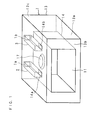
- FIG. 1 is a schematic perspective view for showing the structure of a cooking device according to the present invention
- FIGS. 2 and 3 are partial rear-side perspective views for showing the structure of a cooking device
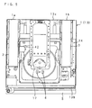
- FIG. 4 is a front view for showing the structure of a cooking device
- FIG. 5 is a partial plan view for showing the structure of a cooking device
- FIG. 6 is a partial rear view for showing the structure of a cooking device
- FIG. 7 is a partial left side view for showing the structure of a cooking device
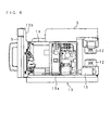
- FIG. 8 is a partial right side view for showing the structure of a cooking device
- FIG. 9 is a schematic sectional view for showing the structure of a cooking device
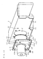
- FIG. 10 is an exploded perspective view for showing the relation between an exhaust duct and a fan
- FIG. 11 is an enlarged sectional view of the part of an exhaust duct and a fan.
- a cooking device shown in FIG. 1 is a microwave oven for heating an object with electromagnetic wave, and comprises: a cooking device body 1 in a substantially rectangular parallelepiped shape, having a heating chamber 11 for heating an object at the front side and electromagnetic generating means 12 behind said heating chamber 11; an exhaust duct 2, which is disposed at one side above the heating chamber 11, for guiding air in the heating chamber 11 to the outside of the cooking device body 1; an air supply duct 3, which is disposed at the other side above the heating chamber 11, for supplying external air to the heating chamber 11; and a fan 4 for discharging air in the heating chamber 11 into the exhaust duct 2.
- the cooking device body 1 has a substantially rectangular parallelepiped shape and comprises: a cabinet 13 which is open in front of the heating chamber 11; a door member 5 for opening and closing an open section at the front side; a housing 14, which is disposed at the front side in the cabinet 13 and has the heating chamber 11; two electromagnetic generating means 12 and 12 disposed behind the housing 14; two transformers 15 and 15 and two cooling fans 16 and 16; electromagnetic supplying means 17 and 17, which are disposed above and under the housing 14, for supplying electromagnetic wave generated by the electromagnetic generating means 12 and 12 to the heating chamber 11; control means for controlling electrical components such as the electromagnetic generating means 12; an operation section for operating the control means; and the like.
- the cabinet 13 comprises: a base 13a having a quadrangular shape; a front frame 13b, which is connected with a front edge section of said base 13a and has an open section; a rear frame 13c attached to a rear edge section of the base 13a; and a covering member 13d, which is provided with both lateral plates and a top plate and has a substantially inverted U-shaped shape.
- the housing 14 is attached to the front side of the base 13a and a door member is supported rotatably at one side of the open section of the front frame 13b.
- a support plate 18 is attached to the rear side of the base 13a, and the electromagnetic generating means 12, the transformers 15 and the cooling fans 16 are respectively attached to the support plate 18 and the base 13a.
- Each electromagnetic generating means 12 is constituted of a magnetron.
- each electromagnetic supplying means 17 comprises a rotating antenna 17a having a radial convex and a motor 17b for driving said rotating antenna 17a.
- An exhaust port 1a having a grille-like shape is provided at one side of an upper section of the rear frame 13c to communicate with an outlet side end of the exhaust duct 2, and an intake port 1b having a grille-like shape is provided at the other side of an upper section of the rear frame 13c to communicate with an inlet side end of the air supply duct 3.
- the housing 14 has a substantially rectangular parallelepiped shape having an open section at the front side, and an outlet port 14a (first port) is provided at one lateral section of a top wall and an inlet port 14b (second port) is provided at the other lateral section as shown in FIG. 9 .
- the outlet port 14a and the inlet port 14b are composed of a plurality of small pores.
- a circular recess 14c is provided at a central section of each of the top wall and the bottom wall, the electromagnetic supplying means 17 are respectively disposed at the recesses 14c, and sensors 6 are provided for detecting driving/suspension of the rotating antennas 17a and cover plates 14d for closing openings of the recesses 14c.
- a shield plate 19 is provided above the heating chamber 11, separated downwards from a top wall including the cover plate 14d so as to form a vent path between the shield plate 19 and said top wall.
- the exhaust duct 2 and the air supply duct 3 are formed to have the same rectangular cylindrical shape provided with both lateral plates, a top plate, a bottom plate and one end plate, an inlet corresponding to the outlet port 14a is provided at the bottom plate of the exhaust duct 2, and an outlet corresponding to the inlet port 14b is provided at the bottom plate of the air supply duct 3.
- the inside of the exhaust duct 2 forms an exhaust guide path for guiding air blown off from the fan 4 to the exhaust port 1a
- the inside of the air supply duct 3 forms an air supply guide path for guiding external air sucked from the intake port 1b to the inlet port 14b.
- the exhaust duct 2 and the air supply duct 3 are disposed backward and forward at both lateral sides of the top wall of the housing 14, and lower edge sections of both lateral plates are attached to the top wall. Moreover, an end plate of the exhaust duct 2 is disposed at the outlet port 14a side and an end plate of the air supply duct 3 is disposed at the inlet port 14b side.
- a circular opening 21 which penetrates in a direction intersecting the air guiding direction of the exhaust guide path and a plurality of threaded holes 22 are provided at one lateral plate 2a at the inlet side.
- the opening 21 is formed to have a diameter larger than that of a bladed wheel 41 in the fan 4.
- a casing 7 for housing the bladed wheel 41 is provided inside the exhaust duct 2 at the inlet side.
- the casing 7 has an arc-shaped guide plane for guiding air current generated by rotation of the bladed wheel 41 to the rotation direction of the bladed wheel 41 and an outlet port which is open from a part of the arc-shaped guide plane to one tangential direction of the arc-shaped guide plane, and the center of the bladed wheel 41 is disposed at an eccentric position decentered to the outlet port side with respect to the center of the arc-shaped guide plane, so that the bladed wheel 41 rotates in a direction opposite to a direction in which the outlet port is provided.
- the outlet port has a rectangular cylindrical shape and is disposed with one face in an extension to the arc-shaped guide plane being parallel to the exhaust guide path at the top plate.
- FIG. 12 is a perspective view for showing the structure of the fan 4
- FIG. 13 is an exploded perspective view for showing the structure of the fan 4
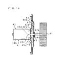
- FIG. 14 is an enlarged sectional view for showing the structure of the fan 4.
- the fan 4 comprises: a motor 42 disposed outside the exhaust duct 2; the bladed wheel 41 which is attached to an output shaft 42a of said motor 42 and disposed rotatably in the casing 7; a mounting plate 43 (first plate) having a central section attached to the motor 42 and an outer edge section attached to the periphery of the opening 21; and a shield plate 44 (second plate) having a shaft hole 44a, into which the output shaft 42a is to be inserted, formed at a central section and an outer edge section attached to a bladed wheel 41 side of the mounting plate 43.
- the motor 42 is provided with a stator and a rotator in a case 42b having a cover plate section at both ends of a cylindrical section, and the output shaft 42a connected with a central section of said rotator is extended outwards from one cover plate section 42c of the case 42b. Moreover, the one cover plate section 42c is provided with a shaft hole 42d into which the output shaft 42a is inserted and a plurality of threaded holes 42e.
- the bladed wheel 41 is a multiblade bladed wheel having a plurality of blades having the rotation center side to be displaced forward in the rotation direction with respect to an outer edge, that is to say, a cylindrical Sirocco bladed wheel wherein a bearing plate is provided at one end and the output shaft 42a is attached to a shaft hole provided at the center of said bearing plate, so that air sucked from the other opening into a cavity at a central section is released from between blades at a peripheral section. It should be noted that a bushing is fitted into the shaft hole and the output shaft 42a is inserted and fitted into said bushing.
- the mounting plate 43 is formed to have a quadrangular shape provided with a circular recess 43a, which has a size corresponding to the outer diameter of the case 42b, at a central section and insertion holes 43b corresponding to the threaded holes 22 at outer edge sections, and is made by pressing an iron plate into shapes.
- the recess 43a is depressed to the motor 42 side, and a shaft hole 43c into which the output shaft 42a is to be inserted and mounting holes 43d corresponding to the threaded holes 42e are provided at the recess 43a.
- a plurality of insertion holes 43e are provided between the recess 43a and the insertion holes 43b, and the outer edge sections of the mounting plate 43 where the insertion holes 43b are provided are displaced to the bladed wheel 41 side by step sections 43f.
- the shield plate 44 is formed to have a quadrangular shape provided with a circular recess 44b, which has a size corresponding to the outer diameter of the bladed wheel 41 and the opening 21, at a central section and threaded holes 44c corresponding to the insertion holes 43e at an outer edge section, and is made by pressing a stainless plate into shapes.
- the recess 44b is depressed to the bladed wheel 41 side, and a cavity having a sealed structure is provided at the periphery of the output shaft 42a between said recess 44b and the recess 43a.
- a shaft hole 44a into which the output shaft 42a is to be inserted is provided at the recess 44b.
- a cylindrical boss 44d is integrally provided at the shaft hole 44a, a flanged sealing tube 45 is fitted into said cylindrical boss 44d, and the output shaft 42a is inserted into said sealing tube 45.
- the recess 44b of the shield plate 44 is formed to have a diameter larger than that of the recess 43a of the mounting plate 43.
- the fan 4 of a cooking device having the above structure is assembled in the following processes.
- the fan 4 assembled as described above can be attached to the exhaust duct 2 by inserting the bladed wheel 41 from the outside of the lateral plate 2a at the exhaust duct 2 through the opening 21 into the casing 7 in the exhaust duct 2, making the mounting plate 43 in contact with the outer face of the lateral plate 2a at the exhaust duct 2, screwing external threads 48 inserted into the insertion holes 43b into the threaded holes 22, and fixing the mounting plate 43 at the lateral plate 2a. Since the bladed wheel 41 can be attached to the output shaft 42a of the motor 42 outside the exhaust duct 2 as described above, it is possible to fix the bladed wheel 41 reliably and to easily and reliably check the fixation state and the dynamic balance of the bladed wheel visually, aurally and tactually.
- the bladed wheel 41 can be pulled from the inside of the casing 7 through the opening 21 to the outside of the exhaust duct 2 by screwing down the external threads 48 so as to unlock the mounting plate 43, and the fan 4 can be detached from the exhaust duct 2. Since the fan 4 can be detached by screwing down the external threads 48 which are to fix the mounting plate 43 as described above, it is possible to achieve cleaning of the fan 4 or replacement of the motor 42 or the like easily, and therefore it is possible to facilitate replacement and maintenance of the cooking device and to shorten shutdown time (down time) of a cooking device for business use, which may reduce profits.
- a cooking device for business use at time required for maintenance, the number of available cooking devices decreases and waiting time for customers lengthens during busy times, causing a problem that customer satisfaction lowers especially in the field of fast-food. Accordingly, the effect of shortening of shutdown time (down time) of a cooking device for business use does not only contribute directly to profits with an increase in operating time but also enhances customer satisfaction and market valuation.
- the control means is made to work by operating the operation section, power is distributed to a magnetron which functions as the electromagnetic generating means 12, electromagnetic wave is supplied from the electromagnetic supplying means 17, which are disposed above and under the heating chamber 11, to the heating chamber 11, an object housed in the heating chamber 11 is cooked, and the fan 4 and the cooling fans 16 are driven.
- the inside of the heating chamber 11 reaches a relatively high temperature during cooking and hot air sometimes up to and rarely exceeding the boiling point and steam are generated.
- the bladed wheel 41 of the fan 4 rotates in a direction opposite to a direction (the one tangential direction) in which the outlet port is provided, air current generated by rotation of the bladed wheel 41 collides with the inner face of the outlet port to be turbulent flow which oscillates upward and downward, and the turbulent flow is blown off into the exhaust duct 2, distributed along the exhaust guide path and discharged from the exhaust port 1a to the outside.
- hot air and steam having a relatively high temperature are distributed in the casing 7 and the exhaust duct 2, and the opening 21 part of the exhaust duct 2 is also exposed to hot air and steam.
- the recess 44b part of the shield plate 44 is located in the opening 21 of the exhaust duct 2, and the mounting plate 43, the shield plate 44 and a cavity between recesses 43a and 44b at the mounting plate 43 and the shield plate 44 shield the motor 42 and the inside of the exhaust duct 2, it is possible to prevent conduction of hot air in the exhaust duct 2 to the motor 42, to depress rise in temperature of the motor 42 and to enhance the durability of the motor 42 to hot air.
- the shaft hole 44d of the shield plate 44 is provided with the sealing tube 45, it is possible to prevent steam in the exhaust duct 2 from outflowing from the periphery of the output shaft 42a to the motor 42 side and to enhance the durability of the motor 42 to steam.
- the embodiment explained above is constructed in such a manner that the mounting plate 43 and the shield plate 44 have the recesses 43a and 44b and the recesses 43a and 44b together define a cavity
- another embodiment may be constructed in such a manner that one of the recesses 43a and 44b is eliminated and the other recess 43a or 44b forms a cavity.
- the embodiment explained above is constructed in such a manner that the exhaust duct 2 and the air supply duct 3 are located above the heating chamber 11, at least one of the exhaust duct 2 and the air supply duct 3 may be located lateral to the heating chamber 11.
- centrifugal fan 4 having a multiblade bladed wheel 41 is used in the embodiment explained above, a centrifugal fan having a radial bladed wheel or a turbo bladed wheel may be used as the fan 4, or an axial fan may be used.
Landscapes
- Engineering & Computer Science (AREA)
- Chemical & Material Sciences (AREA)
- Combustion & Propulsion (AREA)
- Mechanical Engineering (AREA)
- General Engineering & Computer Science (AREA)
- Physics & Mathematics (AREA)
- Electromagnetism (AREA)
- Electric Ovens (AREA)
- Baking, Grill, Roasting (AREA)
- Structures Of Non-Positive Displacement Pumps (AREA)
Claims (6)
- Kochvorrichtung umfassend: einen Kochvorrichtungsaufbau (1) mit einer Heizkammer (11) zum Erwärmen eines Objekts; einen Abluftkanal (2), der mit einem ersten Anschluss (14a), der an einer Wand der Heizkammer (11) vorgesehen ist, und mit der Außenseite des Kochvorrichtungsaufbaus (1) verbunden ist; und einen Lüfter (4) zum Ableiten der Luft in der Heizkammer (11), wobei der Lüfter (4) Luft vom ersten Anschluss (14a) ansaugt und die Luft, die vom Lüfter (4) abgelassen wird, durch den Abluftkanal (2) geleitet und aus dem Kochvorrichtungsaufbau (1) abgesaugt wird, dadurch gekennzeichnet, dass
der Abluftkanal (2) eine Öffnung (21) an einer Wand in einer Richtung hat, die eine Leitungsrichtung kreuzt,
der Lüfter (4) einen Motor (42) umfasst, der außerhalb des Abluftkanals (2) angeordnet ist, ein Laufrad (41), das an einer Ausgangswelle (42a) des Motors (42) befestigt ist und im Abluftkanal (2) angeordnet ist, eine erste Platte (43), die sich zwischen dem Motor (42) und dem Laufrad (41) befindet, mit einer Wellenbohrung (43c), in die die Ausgangswelle (42a) eingefügt ist, wobei die Öffnung (21) des Abluftkanals (2) mit einer oder beiden der ersten Platte (43) und der zweiten Platte (44) abgedeckt ist, wenn der Lüfter (4) am Abluftkanal (2) befestigt wird,
dadurch gekennnzeichnet, dass eine zweite Platte (44), die sich zwischen der ersten Platte (43) und dem Laufrad (41) befindet, eine Wellenbohrung (44a) hat, in die die Ausgangswelle (42a) eingefügt ist,
ein versiegelndes Rohr (45) in die Wellenbohrung (44a) der zweiten Platte (44) eingepasst ist, und die Ausgangswelle (42a) in die Wellenbohrung (44a) der zweiten Platte (44) über das versiegelnde Rohr (45) eingefügt ist. - Kochvorrichtung nach Anspruch 1, wobei ein Umfang der Wellenbohrung (43c) der ersten Platte (43) am Motor (42) befestigt ist, und ein Außenkantenabschnitt der zweiten Platte (44) mit einer Seite des Laufrads (41) der ersten Platte (43) befestigt ist.
- Kochvorrichtung nach Anspruch 2, wobei das Laufrad (41) so gebildet ist, dass es von der Außenseite des Abluftkanals (2) in die Öffnung (21) eingefügt wird, und die zweite Platte (44) eine Vertiefung (44b) hat, die zur Seite des Laufrads (41) abgesenkt ist.
- Kochvorrichtung nach Anspruch 3, wobei ein Abschnitt der Wellenbohrung (43c) der ersten Platte (43) eine Vertiefung (43a) hat, die zur Seite des Motors (42) abgesenkt ist.
- Kochvorrichtung nach Anspruch 3 oder 4, wobei eine Nabe (44d) in der Wellenbohrung (44a) der zweiten Platte (44) fest eingebaut vorgesehen ist.
- Kochvorrichtung nach einem der Ansprüche 1 bis 5 ferner umfassend einen Zuluftkanal (3), der mit einem zweiten Anschluss (14b), der an einer Wand der Heizkammer (11) vorgesehen ist, und mit der Außenseite des Kochvorrichtungsaufbaus (1) verbunden ist.
Applications Claiming Priority (1)
| Application Number | Priority Date | Filing Date | Title |
|---|---|---|---|
| JP2008011990A JP4538504B2 (ja) | 2008-01-22 | 2008-01-22 | 加熱調理器 |
Publications (3)
| Publication Number | Publication Date |
|---|---|
| EP2085703A2 EP2085703A2 (de) | 2009-08-05 |
| EP2085703A3 EP2085703A3 (de) | 2012-06-20 |
| EP2085703B1 true EP2085703B1 (de) | 2015-10-21 |
Family
ID=40512410
Family Applications (1)
| Application Number | Title | Priority Date | Filing Date |
|---|---|---|---|
| EP09000118.1A Ceased EP2085703B1 (de) | 2008-01-22 | 2009-01-08 | Kochvorrichtung |
Country Status (4)
| Country | Link |
|---|---|
| US (1) | US7992552B2 (de) |
| EP (1) | EP2085703B1 (de) |
| JP (1) | JP4538504B2 (de) |
| CN (1) | CN101493234B (de) |
Families Citing this family (31)
| Publication number | Priority date | Publication date | Assignee | Title |
|---|---|---|---|---|
| KR100889132B1 (ko) * | 2007-04-12 | 2009-03-17 | 엘지전자 주식회사 | 오븐 |
| JP4731575B2 (ja) * | 2008-01-22 | 2011-07-27 | シャープ株式会社 | 加熱調理器 |
| US8258435B2 (en) * | 2008-12-16 | 2012-09-04 | Whirlpool Corporation | Dual fan convection oven |
| DE102010042206B4 (de) | 2010-10-08 | 2022-06-30 | BSH Hausgeräte GmbH | Luftführungsvorrichtung für ein Gargerät sowie Verfahren zur Montage einer Luftführungsvorrichtung |
| US8578924B2 (en) * | 2011-07-27 | 2013-11-12 | Bsh Home Appliances Corporation | Exhaust baffle for kitchen appliance |
| DE102012215263A1 (de) * | 2012-08-28 | 2014-03-06 | BSH Bosch und Siemens Hausgeräte GmbH | Gargerät |
| US9551494B2 (en) * | 2014-03-20 | 2017-01-24 | Haier Us Appliance Solutions, Inc. | Mounting bracket with thermal maze to reduce heat transfer rate |
| US10080262B2 (en) * | 2014-05-26 | 2018-09-18 | Sharp Kabushiki Kaisha | Cooking device |
| US20170227238A1 (en) * | 2016-02-09 | 2017-08-10 | Wolf Appliance, Inc. | Convection fan |
| WO2018056977A1 (en) | 2016-09-22 | 2018-03-29 | Whirlpool Corporation | Method and system for radio frequency electromagnetic energy delivery |
| WO2018075026A1 (en) | 2016-10-19 | 2018-04-26 | Whirlpool Corporation | Method and device for electromagnetic cooking using closed loop control |
| WO2018075025A1 (en) | 2016-10-19 | 2018-04-26 | Whirlpool Corporation | Food load cooking time modulation |
| WO2018075030A1 (en) | 2016-10-19 | 2018-04-26 | Whirlpool Corporation | System and method for food preparation utilizing a multi-layer model |
| US11109454B2 (en) | 2016-11-18 | 2021-08-31 | Whirlpool Corporation | Waveguide for microwave ovens with multiple feeding ports RF power control system and method thereof |
| US11197355B2 (en) | 2016-12-22 | 2021-12-07 | Whirlpool Corporation | Method and device for electromagnetic cooking using non-centered loads |
| EP3560291A4 (de) | 2016-12-22 | 2020-11-25 | Whirlpool Corporation | Verfahren und vorrichtung zum elektromagnetischen kochen unter verwendung von nicht-zentriertem lastmanagement durch spektromodale achsenrotation |
| WO2018125143A1 (en) | 2016-12-29 | 2018-07-05 | Whirlpool Corporation | Detecting changes in food load characteristics using q-factor |
| US11483906B2 (en) | 2016-12-29 | 2022-10-25 | Whirlpool Corporation | System and method for detecting cooking level of food load |
| US11102854B2 (en) | 2016-12-29 | 2021-08-24 | Whirlpool Corporation | System and method for controlling a heating distribution in an electromagnetic cooking device |
| US11917743B2 (en) | 2016-12-29 | 2024-02-27 | Whirlpool Corporation | Electromagnetic cooking device with automatic melt operation and method of controlling cooking in the electromagnetic cooking device |
| WO2018125146A1 (en) | 2016-12-29 | 2018-07-05 | Whirlpool Corporation | Electromagnetic cooking device with automatic boiling detection and method of controlling cooking in the electromagnetic cooking device |
| WO2018125130A1 (en) | 2016-12-29 | 2018-07-05 | Whirlpool Corporation | System and method for controlling power for a cooking device |
| US11503679B2 (en) | 2016-12-29 | 2022-11-15 | Whirlpool Corporation | Electromagnetic cooking device with automatic popcorn popping feature and method of controlling cooking in the electromagnetic device |
| WO2018125137A1 (en) | 2016-12-29 | 2018-07-05 | Whirlpool Corporation | System and method for analyzing a frequency response of an electromagnetic cooking device |
| US11452182B2 (en) | 2016-12-29 | 2022-09-20 | Whirlpool Corporation | System and method for detecting changes in food load characteristics using coefficient of variation of efficiency |
| EP3563635B1 (de) | 2016-12-29 | 2022-09-28 | Whirlpool Corporation | Elektromagnetische kochvorrichtung mit automatischer flüssigkeitserhitzung und verfahren zur kochsteuerung bei der elektromagnetischen kochvorrichtung |
| US11412585B2 (en) | 2016-12-29 | 2022-08-09 | Whirlpool Corporation | Electromagnetic cooking device with automatic anti-splatter operation |
| US10488054B2 (en) * | 2017-02-28 | 2019-11-26 | Haier Us Appliance Solutions, Inc. | Cooking appliance and cooling assembly therefor |
| TR201913209A2 (tr) * | 2019-09-02 | 2021-03-22 | Arcelik As | Sizdirmazlik elemani i̇çeren bi̇r pi̇şi̇ri̇ci̇ ci̇haz |
| CN111000456B (zh) * | 2019-12-31 | 2022-03-22 | 广东美的厨房电器制造有限公司 | 烤箱 |
| WO2022060305A1 (en) * | 2020-09-17 | 2022-03-24 | Femas Metal San. Ve Tic. A.S. | Oven with a cooling air fan |
Family Cites Families (22)
| Publication number | Priority date | Publication date | Assignee | Title |
|---|---|---|---|---|
| US2800272A (en) * | 1955-01-31 | 1957-07-23 | Laird C Mckee | Blower unit |
| US3264506A (en) * | 1962-06-27 | 1966-08-02 | Gen Motors Corp | Dynamoelectric machine |
| US3170621A (en) * | 1963-10-23 | 1965-02-23 | Centriflo Pty Ltd | Apparatus for exhausting fumes from factories and the like |
| US3327610A (en) * | 1965-09-13 | 1967-06-27 | Gen Electric | Mounting means for motor-blower unit |
| JPS50127004A (de) | 1974-03-22 | 1975-10-06 | ||
| JPS50127004U (de) * | 1974-04-01 | 1975-10-18 | ||
| JPS5655528Y2 (de) * | 1977-08-10 | 1981-12-25 | ||
| CA1165822A (en) * | 1981-01-14 | 1984-04-17 | William J. Day, Jr. | Combination microwave gas convection oven |
| JPS5861365A (ja) * | 1981-10-07 | 1983-04-12 | Nishishiba Denki Kk | 軸封装置 |
| JPH0381599A (ja) * | 1989-08-25 | 1991-04-05 | Rinnai Corp | 遠心式送風機のスクロールケース |
| US5166487A (en) * | 1989-12-15 | 1992-11-24 | Tecogen, Inc. | Cooking oven with convection and microwave heating |
| US5258675A (en) * | 1991-10-15 | 1993-11-02 | Marathon Electric Manufacturing Corporation | Mount apparatus for rotatable apparatus coupled to a rotating drive unit |
| JPH06185736A (ja) | 1992-12-15 | 1994-07-08 | Matsushita Electric Ind Co Ltd | 加熱調理器 |
| US5444922A (en) * | 1994-09-08 | 1995-08-29 | George Koch Sons, Inc. | Corrugated product dryer |
| DE19734767C1 (de) * | 1997-08-11 | 1999-04-08 | Bosch Siemens Hausgeraete | Backofen mit Kühlluftgebläse |
| JP2000161671A (ja) * | 1998-11-20 | 2000-06-16 | Toshiba Corp | 加熱調理器 |
| JP3422360B2 (ja) * | 1999-03-18 | 2003-06-30 | シャープ株式会社 | 加熱調理器 |
| KR100694255B1 (ko) * | 2000-12-30 | 2007-03-14 | 주식회사 엘지이아이 | 전자레인지의 벤트모터조립체의 구조 |
| CN1523284A (zh) | 2003-02-21 | 2004-08-25 | 乐金电子(天津)电器有限公司 | 用于带有通风罩的微波炉的湿度感知装置 |
| KR20050053946A (ko) * | 2003-12-03 | 2005-06-10 | 삼성전자주식회사 | 벽걸이형 전자렌지 |
| KR20050056724A (ko) * | 2003-12-10 | 2005-06-16 | 삼성전자주식회사 | 벽걸이형 전자렌지 |
| ATE327438T1 (de) * | 2004-03-05 | 2006-06-15 | Fiat Ricerche | Motor-verdichteraggregat für kraftfahrzeuge |
-
2008
- 2008-01-22 JP JP2008011990A patent/JP4538504B2/ja not_active Expired - Fee Related
-
2009
- 2009-01-08 EP EP09000118.1A patent/EP2085703B1/de not_active Ceased
- 2009-01-12 US US12/351,904 patent/US7992552B2/en not_active Expired - Fee Related
- 2009-01-20 CN CN2009100056059A patent/CN101493234B/zh not_active Expired - Fee Related
Also Published As
| Publication number | Publication date |
|---|---|
| CN101493234B (zh) | 2011-07-20 |
| EP2085703A3 (de) | 2012-06-20 |
| JP4538504B2 (ja) | 2010-09-08 |
| EP2085703A2 (de) | 2009-08-05 |
| US7992552B2 (en) | 2011-08-09 |
| CN101493234A (zh) | 2009-07-29 |
| US20090183724A1 (en) | 2009-07-23 |
| JP2009174743A (ja) | 2009-08-06 |
Similar Documents
| Publication | Publication Date | Title |
|---|---|---|
| EP2085703B1 (de) | Kochvorrichtung | |
| US11025122B2 (en) | Fan motor | |
| EP4211400B1 (de) | Ofen | |
| JP2009008297A (ja) | 加熱調理器 | |
| CN213746907U (zh) | 底板组件及烹饪器具 | |
| JP4525535B2 (ja) | 誘導加熱調理器 | |
| KR20020055265A (ko) | 후드겸용 전자레인지의 전장부품 냉각구조 | |
| JP4996994B2 (ja) | 加熱調理器 | |
| CN213721513U (zh) | 底板组件及具有其的烹饪器具 | |
| JP3966052B2 (ja) | 誘導加熱調理器 | |
| JP5011001B2 (ja) | 加熱調理器 | |
| CN215777533U (zh) | 烹饪器具 | |
| JP2019046726A (ja) | 誘導加熱調理器 | |
| CN114322002A (zh) | 底板组件及烹饪器具 | |
| CN114271687A (zh) | 散热风机、底板组件及烹饪器具 | |
| JP2009054438A (ja) | 誘導加熱調理器 | |
| JP7216686B2 (ja) | 加熱調理器 | |
| CN112524061A (zh) | 送风装置和机电设备 | |
| CN215272098U (zh) | 烹饪器具 | |
| JP2011007080A (ja) | 遠心ファン及びそれを用いた加熱調理器 | |
| CN211673862U (zh) | 散热结构、家用电器和食物处理器 | |
| JP2011099643A (ja) | 加熱調理器 | |
| JP4877336B2 (ja) | 誘導加熱調理器 | |
| KR100621034B1 (ko) | 후드겸용 전자레인지의 전장부품 냉각구조 | |
| CN114305141A (zh) | 底板组件及具有其的烹饪器具 |
Legal Events
| Date | Code | Title | Description |
|---|---|---|---|
| PUAI | Public reference made under article 153(3) epc to a published international application that has entered the european phase |
Free format text: ORIGINAL CODE: 0009012 |
|
| AK | Designated contracting states |
Kind code of ref document: A2 Designated state(s): AT BE BG CH CY CZ DE DK EE ES FI FR GB GR HR HU IE IS IT LI LT LU LV MC MK MT NL NO PL PT RO SE SI SK TR |
|
| AX | Request for extension of the european patent |
Extension state: AL BA RS |
|
| PUAL | Search report despatched |
Free format text: ORIGINAL CODE: 0009013 |
|
| AK | Designated contracting states |
Kind code of ref document: A3 Designated state(s): AT BE BG CH CY CZ DE DK EE ES FI FR GB GR HR HU IE IS IT LI LT LU LV MC MK MT NL NO PL PT RO SE SI SK TR |
|
| AX | Request for extension of the european patent |
Extension state: AL BA RS |
|
| RIC1 | Information provided on ipc code assigned before grant |
Ipc: F24C 15/32 20060101AFI20120516BHEP Ipc: H05B 6/64 20060101ALI20120516BHEP |
|
| 17P | Request for examination filed |
Effective date: 20120808 |
|
| AKX | Designation fees paid |
Designated state(s): DE FR GB |
|
| GRAP | Despatch of communication of intention to grant a patent |
Free format text: ORIGINAL CODE: EPIDOSNIGR1 |
|
| INTG | Intention to grant announced |
Effective date: 20150507 |
|
| GRAS | Grant fee paid |
Free format text: ORIGINAL CODE: EPIDOSNIGR3 |
|
| GRAA | (expected) grant |
Free format text: ORIGINAL CODE: 0009210 |
|
| AK | Designated contracting states |
Kind code of ref document: B1 Designated state(s): DE FR GB |
|
| REG | Reference to a national code |
Ref country code: GB Ref legal event code: FG4D |
|
| REG | Reference to a national code |
Ref country code: DE Ref legal event code: R096 Ref document number: 602009034295 Country of ref document: DE |
|
| REG | Reference to a national code |
Ref country code: FR Ref legal event code: PLFP Year of fee payment: 8 |
|
| REG | Reference to a national code |
Ref country code: DE Ref legal event code: R097 Ref document number: 602009034295 Country of ref document: DE |
|
| PLBE | No opposition filed within time limit |
Free format text: ORIGINAL CODE: 0009261 |
|
| STAA | Information on the status of an ep patent application or granted ep patent |
Free format text: STATUS: NO OPPOSITION FILED WITHIN TIME LIMIT |
|
| 26N | No opposition filed |
Effective date: 20160722 |
|
| REG | Reference to a national code |
Ref country code: FR Ref legal event code: PLFP Year of fee payment: 9 |
|
| REG | Reference to a national code |
Ref country code: FR Ref legal event code: PLFP Year of fee payment: 10 |
|
| PGFP | Annual fee paid to national office [announced via postgrant information from national office to epo] |
Ref country code: FR Payment date: 20210121 Year of fee payment: 13 |
|
| PGFP | Annual fee paid to national office [announced via postgrant information from national office to epo] |
Ref country code: DE Payment date: 20210120 Year of fee payment: 13 |
|
| REG | Reference to a national code |
Ref country code: DE Ref legal event code: R119 Ref document number: 602009034295 Country of ref document: DE |
|
| PG25 | Lapsed in a contracting state [announced via postgrant information from national office to epo] |
Ref country code: DE Free format text: LAPSE BECAUSE OF NON-PAYMENT OF DUE FEES Effective date: 20220802 |
|
| PG25 | Lapsed in a contracting state [announced via postgrant information from national office to epo] |
Ref country code: FR Free format text: LAPSE BECAUSE OF NON-PAYMENT OF DUE FEES Effective date: 20220131 |
|
| PGFP | Annual fee paid to national office [announced via postgrant information from national office to epo] |
Ref country code: GB Payment date: 20240119 Year of fee payment: 16 |
|
| GBPC | Gb: european patent ceased through non-payment of renewal fee |
Effective date: 20250108 |
|
| PG25 | Lapsed in a contracting state [announced via postgrant information from national office to epo] |
Ref country code: GB Free format text: LAPSE BECAUSE OF NON-PAYMENT OF DUE FEES Effective date: 20250108 |