EP2085732B1 - Echangeur thermique en verre avec plaque tubulaire en plastique - Google Patents
Echangeur thermique en verre avec plaque tubulaire en plastique Download PDFInfo
- Publication number
- EP2085732B1 EP2085732B1 EP20080151043 EP08151043A EP2085732B1 EP 2085732 B1 EP2085732 B1 EP 2085732B1 EP 20080151043 EP20080151043 EP 20080151043 EP 08151043 A EP08151043 A EP 08151043A EP 2085732 B1 EP2085732 B1 EP 2085732B1
- Authority
- EP
- European Patent Office
- Prior art keywords
- heat exchanger
- tube
- glass tubes
- bases
- der
- Prior art date
- Legal status (The legal status is an assumption and is not a legal conclusion. Google has not performed a legal analysis and makes no representation as to the accuracy of the status listed.)
- Not-in-force
Links
- 239000011521 glass Substances 0.000 title claims description 104
- 239000004033 plastic Substances 0.000 title claims description 26
- 229920003023 plastic Polymers 0.000 title claims description 26
- 230000003014 reinforcing effect Effects 0.000 claims description 44
- 239000012530 fluid Substances 0.000 claims description 32
- 239000002184 metal Substances 0.000 claims description 26
- 229910052751 metal Inorganic materials 0.000 claims description 26
- 238000007689 inspection Methods 0.000 claims description 8
- 238000009827 uniform distribution Methods 0.000 claims description 2
- 230000002093 peripheral effect Effects 0.000 claims 1
- 239000007789 gas Substances 0.000 description 35
- 238000004519 manufacturing process Methods 0.000 description 14
- XLYOFNOQVPJJNP-UHFFFAOYSA-N water Substances O XLYOFNOQVPJJNP-UHFFFAOYSA-N 0.000 description 10
- 238000005260 corrosion Methods 0.000 description 9
- 230000007797 corrosion Effects 0.000 description 9
- 238000009434 installation Methods 0.000 description 8
- 238000004891 communication Methods 0.000 description 7
- 238000009413 insulation Methods 0.000 description 6
- 239000000463 material Substances 0.000 description 6
- 229920000642 polymer Polymers 0.000 description 5
- 238000007789 sealing Methods 0.000 description 4
- 239000000919 ceramic Substances 0.000 description 3
- 230000007774 longterm Effects 0.000 description 3
- 241001295925 Gegenes Species 0.000 description 2
- PXHVJJICTQNCMI-UHFFFAOYSA-N Nickel Chemical compound [Ni] PXHVJJICTQNCMI-UHFFFAOYSA-N 0.000 description 2
- 239000004734 Polyphenylene sulfide Substances 0.000 description 2
- 239000000853 adhesive Substances 0.000 description 2
- 230000001070 adhesive effect Effects 0.000 description 2
- 239000000956 alloy Substances 0.000 description 2
- 229910045601 alloy Inorganic materials 0.000 description 2
- 230000015572 biosynthetic process Effects 0.000 description 2
- 238000004140 cleaning Methods 0.000 description 2
- 238000002485 combustion reaction Methods 0.000 description 2
- 238000011109 contamination Methods 0.000 description 2
- 238000011161 development Methods 0.000 description 2
- 238000005516 engineering process Methods 0.000 description 2
- 238000010438 heat treatment Methods 0.000 description 2
- 230000003993 interaction Effects 0.000 description 2
- 238000012423 maintenance Methods 0.000 description 2
- 238000000034 method Methods 0.000 description 2
- 239000000203 mixture Substances 0.000 description 2
- 239000006223 plastic coating Substances 0.000 description 2
- 229920000069 polyphenylene sulfide Polymers 0.000 description 2
- 239000004800 polyvinyl chloride Substances 0.000 description 2
- 229920000915 polyvinyl chloride Polymers 0.000 description 2
- 239000010935 stainless steel Substances 0.000 description 2
- 229910001220 stainless steel Inorganic materials 0.000 description 2
- 241001156002 Anthonomus pomorum Species 0.000 description 1
- 229920000049 Carbon (fiber) Polymers 0.000 description 1
- 239000004063 acid-resistant material Substances 0.000 description 1
- 238000004026 adhesive bonding Methods 0.000 description 1
- 238000005452 bending Methods 0.000 description 1
- 239000004917 carbon fiber Substances 0.000 description 1
- YACLQRRMGMJLJV-UHFFFAOYSA-N chloroprene Chemical compound ClC(=C)C=C YACLQRRMGMJLJV-UHFFFAOYSA-N 0.000 description 1
- 239000011248 coating agent Substances 0.000 description 1
- 238000000576 coating method Methods 0.000 description 1
- 239000002131 composite material Substances 0.000 description 1
- 238000009833 condensation Methods 0.000 description 1
- 230000005494 condensation Effects 0.000 description 1
- 239000000470 constituent Substances 0.000 description 1
- 238000001816 cooling Methods 0.000 description 1
- 238000005520 cutting process Methods 0.000 description 1
- 230000001419 dependent effect Effects 0.000 description 1
- 238000013461 design Methods 0.000 description 1
- 230000007613 environmental effect Effects 0.000 description 1
- 230000002349 favourable effect Effects 0.000 description 1
- 239000012467 final product Substances 0.000 description 1
- 239000000446 fuel Substances 0.000 description 1
- 239000003365 glass fiber Substances 0.000 description 1
- 238000000227 grinding Methods 0.000 description 1
- 231100001261 hazardous Toxicity 0.000 description 1
- 238000001746 injection moulding Methods 0.000 description 1
- 238000002386 leaching Methods 0.000 description 1
- 239000007788 liquid Substances 0.000 description 1
- 239000007769 metal material Substances 0.000 description 1
- 150000002739 metals Chemical class 0.000 description 1
- VNWKTOKETHGBQD-UHFFFAOYSA-N methane Chemical compound C VNWKTOKETHGBQD-UHFFFAOYSA-N 0.000 description 1
- 239000002991 molded plastic Substances 0.000 description 1
- 229910052759 nickel Inorganic materials 0.000 description 1
- 238000005192 partition Methods 0.000 description 1
- 238000001556 precipitation Methods 0.000 description 1
- 230000002787 reinforcement Effects 0.000 description 1
- 239000010801 sewage sludge Substances 0.000 description 1
- 239000007787 solid Substances 0.000 description 1
- 239000000243 solution Substances 0.000 description 1
- 238000012549 training Methods 0.000 description 1
- 239000004636 vulcanized rubber Substances 0.000 description 1
Images





Classifications
-
- F—MECHANICAL ENGINEERING; LIGHTING; HEATING; WEAPONS; BLASTING
- F28—HEAT EXCHANGE IN GENERAL
- F28D—HEAT-EXCHANGE APPARATUS, NOT PROVIDED FOR IN ANOTHER SUBCLASS, IN WHICH THE HEAT-EXCHANGE MEDIA DO NOT COME INTO DIRECT CONTACT
- F28D7/00—Heat-exchange apparatus having stationary tubular conduit assemblies for both heat-exchange media, the media being in contact with different sides of a conduit wall
- F28D7/16—Heat-exchange apparatus having stationary tubular conduit assemblies for both heat-exchange media, the media being in contact with different sides of a conduit wall the conduits being arranged in parallel spaced relation
-
- F—MECHANICAL ENGINEERING; LIGHTING; HEATING; WEAPONS; BLASTING
- F28—HEAT EXCHANGE IN GENERAL
- F28D—HEAT-EXCHANGE APPARATUS, NOT PROVIDED FOR IN ANOTHER SUBCLASS, IN WHICH THE HEAT-EXCHANGE MEDIA DO NOT COME INTO DIRECT CONTACT
- F28D7/00—Heat-exchange apparatus having stationary tubular conduit assemblies for both heat-exchange media, the media being in contact with different sides of a conduit wall
- F28D7/16—Heat-exchange apparatus having stationary tubular conduit assemblies for both heat-exchange media, the media being in contact with different sides of a conduit wall the conduits being arranged in parallel spaced relation
- F28D7/1607—Heat-exchange apparatus having stationary tubular conduit assemblies for both heat-exchange media, the media being in contact with different sides of a conduit wall the conduits being arranged in parallel spaced relation with particular pattern of flow of the heat exchange media, e.g. change of flow direction
-
- F—MECHANICAL ENGINEERING; LIGHTING; HEATING; WEAPONS; BLASTING
- F28—HEAT EXCHANGE IN GENERAL
- F28F—DETAILS OF HEAT-EXCHANGE AND HEAT-TRANSFER APPARATUS, OF GENERAL APPLICATION
- F28F21/00—Constructions of heat-exchange apparatus characterised by the selection of particular materials
- F28F21/006—Constructions of heat-exchange apparatus characterised by the selection of particular materials of glass
-
- F—MECHANICAL ENGINEERING; LIGHTING; HEATING; WEAPONS; BLASTING
- F28—HEAT EXCHANGE IN GENERAL
- F28F—DETAILS OF HEAT-EXCHANGE AND HEAT-TRANSFER APPARATUS, OF GENERAL APPLICATION
- F28F21/00—Constructions of heat-exchange apparatus characterised by the selection of particular materials
- F28F21/06—Constructions of heat-exchange apparatus characterised by the selection of particular materials of plastics material
- F28F21/067—Details
-
- F—MECHANICAL ENGINEERING; LIGHTING; HEATING; WEAPONS; BLASTING
- F28—HEAT EXCHANGE IN GENERAL
- F28D—HEAT-EXCHANGE APPARATUS, NOT PROVIDED FOR IN ANOTHER SUBCLASS, IN WHICH THE HEAT-EXCHANGE MEDIA DO NOT COME INTO DIRECT CONTACT
- F28D21/00—Heat-exchange apparatus not covered by any of the groups F28D1/00 - F28D20/00
- F28D21/0001—Recuperative heat exchangers
- F28D21/0003—Recuperative heat exchangers the heat being recuperated from exhaust gases
-
- F—MECHANICAL ENGINEERING; LIGHTING; HEATING; WEAPONS; BLASTING
- F28—HEAT EXCHANGE IN GENERAL
- F28F—DETAILS OF HEAT-EXCHANGE AND HEAT-TRANSFER APPARATUS, OF GENERAL APPLICATION
- F28F2225/00—Reinforcing means
- F28F2225/08—Reinforcing means for header boxes
-
- F—MECHANICAL ENGINEERING; LIGHTING; HEATING; WEAPONS; BLASTING
- F28—HEAT EXCHANGE IN GENERAL
- F28F—DETAILS OF HEAT-EXCHANGE AND HEAT-TRANSFER APPARATUS, OF GENERAL APPLICATION
- F28F2275/00—Fastening; Joining
- F28F2275/20—Fastening; Joining with threaded elements
- F28F2275/205—Fastening; Joining with threaded elements with of tie-rods
-
- F—MECHANICAL ENGINEERING; LIGHTING; HEATING; WEAPONS; BLASTING
- F28—HEAT EXCHANGE IN GENERAL
- F28F—DETAILS OF HEAT-EXCHANGE AND HEAT-TRANSFER APPARATUS, OF GENERAL APPLICATION
- F28F9/00—Casings; Header boxes; Auxiliary supports for elements; Auxiliary members within casings
- F28F9/02—Header boxes; End plates
- F28F9/04—Arrangements for sealing elements into header boxes or end plates
- F28F9/06—Arrangements for sealing elements into header boxes or end plates by dismountable joints
Definitions
- the invention relates to a heat exchanger, comprising a plurality of, preferably arranged substantially parallel to each other, can be flowed through by a fluid glass tubes, a first tube plate with openings into which the glass tubes are introduced with a first end, a second tube plate with openings, in which the Glass tubes are introduced with a second end, wherein at least one of the two tube sheets, preferably both tube plates, is at least partially made of plastic or are.
- the invention relates to a heat exchanger series, comprising two or more heat exchangers with different power classes.
- Heat exchangers of the type mentioned are used for numerous processes in various technical applications.
- a typical use is as a secondary heat exchanger for boilers where they are used to heat a liquid while cooling down and possibly condensing exhaust gases from a burner of a boiler.
- the glass tubes are usually made of a fluid medium, in particular water, flows through and the exhaust gases flow around the glass tubes flowed through by the medium.
- the exhaust gas of the boiler can be cooled so far that the water vapor components of the exhaust gas, which are formed in the combustion of hydrocarbonaceous fuels in the burner, condense. By utilizing the resulting condensation heat, a significant improvement of the combustion efficiency occurs.
- Heat exchangers of the type mentioned above are often referred to as tube bundle heat exchangers, since in them often a plurality of tubes, which are usually aligned in parallel and thereby form a tube bundle, are used.
- Heat exchangers are known with glass tubes whose tubesheets are made of metal. Although this has some advantages in terms of production engineering and also with regard to the strength of the mechanically and thermally highly stressed tube sheets, metal tube sheets cause a problem of corrosion which prematurely triggers an early technical failure of the heat exchangers due to the interaction of heat, corrosive aggressive components of the exhaust gas and their condensates to pull oneself.
- the DE 31 39 794 C2 proposes with respect to the problem of tightness specific complex seals between the glass tubes and the plastic tube floors.
- the glass tubes of each one arranged in an annular groove with play in the longitudinal direction ring of chloroprene polymer held, which in turn is housed in sleeve rings.
- the sleeve rings are glued into the bottom of a pot-like container, the annular flange is sealed at the top. If the sleeve rings already consist of hard polyvinyl chloride, an adhesive can be used to bond the sleeve ring to the cup-shaped container.
- the sleeve rings are made of or coated with a fluorocarbonate, it is necessary to etch the splices before the adhesive is applied.
- the production cost increases significantly by this type of complex sealing.
- Heat exchanger with plastic tube bottoms, as in the DE 31 39 794 C2 therefore, could not prevail in practice, especially not as a heat exchanger higher performance class.
- a heat exchanger of the type mentioned solves this object according to the invention by the features of the characterizing part of claim 1, wherein one, two or more rod-shaped reinforcing elements, each extending from an attachment point on the first tube sheet to an attachment point on the second tube sheet, preferably substantially parallel to the Glass tubes, and are attached to the tube plates such that they reduce deformation of the tubesheets or parts thereof, in particular a deflection or bulge in the longitudinal direction of the glass tubes, at least in sections.
- the respective ends of the glass tubes of the heat exchanger according to the invention are introduced into the openings in the tubesheets and sealed.
- the sealing takes place for example via O-rings.
- the tube plates of a heat exchanger are under the pressure (for example, about 1.5 bar) of this fluid medium, which rests against the side facing away from the glass tubes sides of the tube sheets.
- the invention is based on the finding that this often results in plastic tube sheets not according to the invention, on the one hand elastic, but on the other hand also plastic (visco-elastic) deformations of the tube sheets or parts thereof.
- the high temperatures of the exhaust gas (for example, over 200 ° C), as well as the temperature of the fluid medium represent a further burden of the tube sheets and favor their deformation. This deformation was recognized as the cause of the leak.
- the tube plates of a heat exchanger according to the invention consist partially or completely of plastic. Suitable materials are those which can withstand the boundary conditions usually encountered during use (for example pressure of about 1.5 bar, temperatures of about 200 ° C., condensate composition). For example, plastics such as glass fiber or carbon fiber reinforced polyphenylene sulfide (PPS) can be used.
- PPS polyphenylene sulfide
- the tubesheets of a heat exchanger according to the invention each have one, two or more attachment points for receiving one, two or more rod-shaped reinforcing elements. If in the following remarks on rod-shaped reinforcing elements in Singular or plural reference, the statements also apply to the unmentioned plural or singular.
- rod-shaped reinforcing elements are fastened with their first ends to the attachment points of the first tube plate and with their second ends to the attachment points of the second tube plate.
- the number of attachment locations per tube plate is preferably equal to or higher than the number of rod-shaped reinforcement elements. It is preferred that the rod-shaped reinforcing elements are arranged parallel to the glass tubes. However, it is also possible to let the rod-shaped reinforcing elements extend at an angle to the glass tubes.
- the rod-shaped reinforcing elements can be attached to the attachment points of the tube sheets, for example by inserting, clamping, screwing, riveting or gluing.
- the attachment points on the tubesheets may be, for example, holes, recesses or projections, but they may for example also be formed as a surface or part of a surface.
- rod-shaped reinforcing elements limit the deformation possibilities of the tube sheets.
- a deflection or bulging of the tubesheets or parts thereof in the longitudinal direction of the glass tubes can be reduced at least in sections by the rod-shaped reinforcing elements.
- the rod-shaped reinforcing elements serve as pressure rods, that is, a deformation of the tube plates or the mutually assigning tube plate walls is reduced in the direction of the glass tubes. This advantageously makes it possible to stiffen the tubesheets against deformation of the tubesheets toward one another.
- the rod-shaped reinforcing elements can serve as tension rods, in order to at least partially reduce deformation of the tube plates away from the glass tubes.
- Each individual rod-shaped connecting element prevents deformation of a tube plate or parts thereof, in particular in the region of the attachment point of the tube plate and in adjacent areas.
- the deformation of parts of the tubesheet which are further away from a reinforcing element can be reduced by the reinforcing element.
- the reinforcing elements By varying the number and arrangement of the reinforcing elements, these can be designed for the respective performance class and operating conditions of the heat exchanger.
- the glass heat exchanger according to the invention has the advantage that the long-term stability of a heat exchanger according to the invention can be increased, since in particular a deformation of the tube plate endangering the sealing between glass tubes and tubesheet is prevented by the reinforcing elements.
- a further advantage is that the tubesheets of a heat exchanger according to the invention are preferably formed entirely of plastic and thus are inexpensive to manufacture, in particular much cheaper than tube sheets made of metal.
- the use of tubesheets whose parts in contact with the exhaust gas or the condensate are made of plastic, in combination with glass tubes, furthermore has the advantage that the condensate formed during use of the heat exchanger is not contaminated by metal components.
- the advantages shown can also be achieved or improved by supporting one, two or more of the glass tubes on both sides with an axial stop in the tubesheets and matching the length of the glass tubes exactly to the distance between the glass tube bottoms is.
- this alternative is less preferred in practice because of the high manufacturing costs involved in manufacturing the glass tubes with correspondingly short length tolerances.
- the invention can be developed by virtue of the fact that the rod-shaped reinforcing element or the rod-shaped reinforcing elements has or have an annular, circular, rectangular, I or T-shaped cross section. Furthermore, the invention can be developed by the fact that the rod-shaped reinforcing element or the rod-shaped reinforcing elements is or are made of glass, stainless steel or ceramic. It is particularly preferred if the rod-shaped reinforcing elements have a cross section, which supports a high pressure stability of the rod-shaped reinforcing elements and has a high stability against bending and buckling.
- the materials used for the rod-shaped reinforcing elements are preferably designed such that on the one hand they withstand the boundary conditions (eg exhaust gas temperatures of about 200 ° C., exhaust gas and condensate composition) and on the other hand have the highest possible strength in order to be used as pressure (if necessary also as tensile) bars to be able to reduce deformation of the tube sheets.
- the rod-shaped reinforcing elements may also be glass tubes, optionally with a smaller diameter than the glass tubes through which the fluid can flow.
- the rod-shaped reinforcing elements can also be solid glass rods. Reinforcing elements of glass or ceramic have the advantage over metals that the exhaust gas condensate is not contaminated. The use of glass can continue to be less expensive than ceramic or metal.
- the invention can be further developed in that the rod-shaped reinforcing element is arranged centrally between the two tubesheets is. Furthermore, the invention can be developed in that a plurality of rod-shaped reinforcing elements are arranged uniformly distributed between the two tube sheets.
- the inventive arrangement of one or more rod-shaped reinforcing elements is particularly preferred in order to reduce the deformation of the tube plates as evenly as possible.
- the central arrangement of a rod-shaped reinforcing element between the two tube plates is particularly advantageous in order to reduce or avoid the deformation of the tubesheets, which is to be expected in the center to a large extent.
- the heat exchanger according to the invention is further characterized in that at least one tube plate, preferably both tubesheets, on its side facing away from the glass tubes has a tube bottom cover which is connected to the tube sheet such that between the tube plate and the tube plate cover a cavity is formed, which with the Glass tubes in fluid communication.
- the tube bottom cover preferably serves to create a cavity on the side of the tubesheet which faces away from the glass tubes, which is in fluid communication with the glass tubes, so that the fluid can circulate in the glass tubes and the cavities located between the tubesheets and tube bottom covers.
- the tube bottom cover may be formed for example of plastic, metal or a combination of materials. The use of metal for the tube bottom cover has the advantage that creep, as can occur in plastic parts, can be avoided. As the tube bottom cover usually not with the exhaust gas or the condensate There is also no risk of contamination of the condensate by metal components.
- the heat exchanger according to the invention is characterized in that the cavity is divided by means of a separating element between the tube sheet and the tube bottom cover into a first and a second cavity portion, wherein the first cavity portion is in fluid communication with a first group of the glass tubes and the second cavity portion with a second Group of glass tubes is in fluid communication.
- a separating element is formed between only one of the two tube plates and the associated tube bottom cover.
- Such an arrangement can advantageously ensure that fluid from the first cavity section of the divided first cavity passes through the first group of glass tubes in fluid communication with this cavity section into the second, non-divided cavity and out of this second, non-divided cavity through the second Group of glass tubes flows back into the second section of the divided first cavity.
- the circulation direction and the number and arrangement of the tubes to be flowed through in a certain direction can be defined.
- This embodiment can be further developed in that the first group comprises fewer glass tubes than the second group.
- the flow rate of the fluid through the groups of glass tubes can be configured differently. In this case, it is particularly preferred to pass incoming, comparatively cold medium at high speed through a smaller number of glass tubes and to allow flowing, comparatively warmer medium to flow back at a lower speed through a larger number of glass tubes.
- the tube bottom cover prefferably has a first connection for connecting the first cavity section to a fluid supply and a second connection for connecting the second cavity section to a fluid discharge.
- the heat exchanger can be integrated into a medium circuit.
- the invention can be further developed by the fact that the first cavity section is arranged in the installed position above the second cavity section.
- This training is particularly advantageous because in this way hot exhaust gas, which preferably flows through the heat exchanger in installation position from top to bottom, first with zuströmendem, d. H. comparatively cold fluid over which glass tube walls come in thermal contact.
- a countercurrent arrangement could be realized, which can bring an advantage in particular with significant temperature increases of the fluid over its flow path.
- the object is achieved by a heat exchanger of the type mentioned, in which at least one of the two tube sheets, preferably both tube sheets, has a groove formed in an outer edge region of its glass tubes side facing receiving a heat exchanger housing , It is preferred that the heat exchanger housing is formed as a U-shaped angled housing plate. Furthermore, it is preferred that the heat exchanger housing is fastened by one, two or more tension elements connecting the tube plates, preferably drawstrings or rods, between the tube plates.
- connection elements required for connecting the tubesheets to a heat exchanger housing can essentially be formed in the tubesheet and the heat exchanger housing can be made, for example, from a simple housing plate which is angled in a U-shape.
- the housing plate may have holes or cutouts, for example for connection to other heat exchanger elements.
- a groove for receiving the heat exchanger housing is advantageously provided. If, as preferred, the tubesheet is completely made of plastic and is produced, for example, by injection molding, the formation of a groove for receiving the heat exchanger housing or the formation of other connecting devices is different than, for example, tube sheets made of metal, manufacturing technology easy and inexpensive to implement.
- the tube sheets and heat exchanger housing In order to establish the connection between tube sheets and heat exchanger housing, it is preferable to connect the tube sheets via tension members, preferably drawstrings, rods or sheets, and in this way to clamp the heat exchanger housing between the two tube sheets and preferably within the groove formed in the tube sheets , If the heat exchanger housing is inserted into the grooves formed in the tube plates and the tubesheets are connected to each other by the tension elements, and the heat exchanger housing is fixed accordingly.
- the connection between the heat exchanger housing and tube sheets is sealed, for example by inserting a seal in the grooves formed in the tubesheets.
- the invention can be further developed by the fact that the heat exchanger housing has a closable inspection opening, which allows maintenance of the heat exchanger in the installed state.
- a closable inspection opening is preferably arranged above or laterally in the installed state of the heat exchanger, so that a user can easily reach the inspection opening.
- a further aspect of the invention is a heat exchanger of the aforementioned type, comprising an exhaust gas collector with an exhaust gas outlet opening, which is characterized in that the exhaust gas collector is arranged such that the exhaust gas outlet opening has a connection cross section has, which allows the connection of an exhaust pipe substantially parallel to the glass tubes.
- a heat exchanger according to the invention typically has an exhaust gas collector with an exhaust gas outlet opening, through which the exhaust gas which has flowed through the heat exchanger can be connected to an exhaust pipe and can be discharged through it.
- the connection cross-section of the outlet opening is arranged so that the exhaust pipe can be connected substantially parallel to the glass tubes.
- the exhaust manifold is designed such that it can be mounted alternatively in a position offset by 180 degrees to the position defined in the preceding claim. It is preferred that the exhaust gas collector is formed symmetrically with respect to the arrangement of the exhaust gas outlet opening in the first installation alternative to the second installation alternative. This further development has the advantage that an installer an increased adaptability is created with respect to the connection possibilities of an exhaust pipe. Furthermore, it is preferred that the exhaust gas collector is arranged in the installed position below the heat exchanger.
- the object can be achieved by a heat exchanger of the type mentioned, in which at least one of the two tube sheets, preferably both tube plates, is formed as a metal plate, wherein the metal plate is partially or completely coated with plastic. Due to the inventive coating of the metal plate with plastic, preferably in all coming into contact with exhaust or condensate parts of the tube sheet, it is ensured that the condensate is not contaminated by metal components. This has the advantage that the mechanical behavior is essentially defined by the material properties of the metal plate. Furthermore, this embodiment facilitates assembly, since the plastic coating can simultaneously serve as a seal between pipes and tube sheet and elastic tolerance compensation and so on an additional seal, for example by means of O-rings can be dispensed with.
- Another aspect of the invention is a heat exchanger series, comprising two or more of the heat exchanger according to the invention with different power classes, characterized in that all heat exchangers of the series have matching tube sheets and the heat exchangers of different power classes differ by the length and / or number of glass tubes.
- the heat exchanger series according to the invention has the advantage that heat exchangers of different power classes can be provided without having to use different tube sheets for this purpose.
- Heat exchangers of different performance classes are realized by installing longer or shorter glass tubes in order to achieve correspondingly high or low performance classes.
- matching tube sheets for all performance classes additional costs can be avoided, as would be required, for example, when adapting the tubesheets or producing individually different tubesheets for different performance classes and, moreover, reducing the manufacturing costs as a whole by mass production of a standardized tube plate.
- heat exchangers of higher power classes can have a higher number of glass tubes than heat exchangers of lower power classes.
- a variation of the number of glass tubes can be realized by closing such openings in the tubesheet which are not intended to receive glass tubes, for example by blind covers be. For this purpose, usually no significant, the geometry of the tubesheet significantly changing changes required, so that the production of the tubesheet can be done very inexpensively.
- the heat exchanger series according to the invention makes it possible to inexpensively provide a modular heat exchanger range for different requirements. This saves compared to the usual provision of oversized heat exchanger for lower power classes in particular material and space. Furthermore, a more flexible and finer gradation of performance classes is possible, since both length and, if appropriate, number of glass tubes can be varied very easily with constant tube plates.
- the heat exchanger series according to the invention can be further developed in that at least one heat exchanger of a higher power class is designed as an arrangement of two preferably identical heat exchangers of a lower power class.
- two heat exchangers can be arranged parallel to each other in installation position and provided with a common heat exchanger housing, so that in the common heat exchanger housing entering exhaust gas flows through the glass tubes of the two composite heat exchanger in parallel.
- three or more, preferably equal, heat exchangers of a lower power class are assembled to form a heat exchanger of higher power class.
- the tube plates of the heat exchanger in such a combination corresponding grooves for receiving a common heat exchanger housing. It is particularly preferred if the course of the grooves is arranged so that the grooves of the tubesheets serve both to receive a heat exchanger housing for only one heat exchanger or, alternatively, to accommodate a common heat exchanger housing for two, three or more heat exchangers.
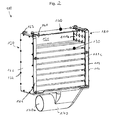
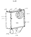
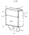
- a U-shaped heat exchanger housing plate 150 and a arranged on the outside of the housing heat insulation 150 a is clamped, as in the Figures 11 and 12 shown.
- the heat exchanger housing plate 150 is formed with its two side edges in each case in a circumferential groove 111 d of the tube plate, which in FIG. 6 is shown, plugged.
- FIG. 9 shows that in the groove 111 d a seal 152 is inserted.
- the two tube sheets 111, 121 are held together by drawstrings 190, which are connected via fastening elements 113, 123 with the two tube plates 111, 121, as in the FIGS. 11 to 13 shown.
- This type of fastening has the advantage that elaborate geometries of the heat exchanger housing 150 can be avoided.
- the tension members 190 are also inexpensive to manufacture components, such as metal bands or strips.
Landscapes
- Engineering & Computer Science (AREA)
- Physics & Mathematics (AREA)
- Thermal Sciences (AREA)
- Mechanical Engineering (AREA)
- General Engineering & Computer Science (AREA)
- Heat-Exchange Devices With Radiators And Conduit Assemblies (AREA)
Claims (16)
- Echangeur de chaleur (100) comprenant- une pluralité de tubes de verre (130) pouvant être traversés par un fluide, disposés de préférence essentiellement de manière parallèle les uns par rapport aux autres,- une première plaque tubulaire (111) dotée d'ouvertures (111a), dans lesquelles les tubes de verre sont introduits par une première extrémité,- une deuxième plaque tubulaire (121) dotée d'ouvertures, dans lesquelles les tubes de verre sont introduits par une deuxième extrémité,- sachant qu'au moins une des deux plaques tubulaires (111, 121), de préférence les deux plaques tubulaires, est ou sont réalisée(s) en matière plastique,caractérisé en ce qu'un, deux ou plusieurs éléments de renforcement (140) présentant une forme de barre s'étendent respectivement depuis un emplacement de fixation au niveau de la première plaque tubulaire en direction d'un emplacement de fixation au niveau de la deuxième plaque tubulaire, de préférence essentiellement de manière parallèle par rapport aux tubes de verre, et sont fixés au niveau des plaques tubulaires de telle manière qu'ils minimisent au moins par endroits, une déformation des plaques tubulaires ou de parties de celles-ci, en particulier un cintrage ou un bombement dans la direction longitudinale des tubes de verre,
et en ce qu'au moins une plaque tubulaire (111, 121), de préférence deux plaques tubulaires, présente sur son côté opposé aux tubes de verre (130) un couvercle de plaque tubulaire (112, 122), qui est relié à la plaque tubulaire de telle manière qu'une cavité est réalisée entre la plaque tubulaire et le couvercle de plaque tubulaire, laquelle cavité est en liaison fluidique avec les tubes de verre (130), sachant que la cavité est divisée, au moyen d'un élément de séparation (115), entre la plaque tubulaire (111) et le couvercle de plaque tubulaire (112), en une première section de cavité et en une deuxième section de cavité, sachant que la première section de cavité est en liaison fluidique avec un premier groupe (130a) des tubes de verre et que la deuxième section de cavité est en liaison fluidique avec un deuxième groupe (130b) des tubes de verre. - Echangeur de chaleur (100) selon la revendication précédente,
caractérisé en ce que l'élément de renforcement (140) présentant une forme de barre est disposé de manière centrale entre les deux plaques tubulaires (111, 121). - Echangeur de chaleur (100) selon l'une quelconque des revendications précédentes,
caractérisé en ce que plusieurs éléments de renforcement (140) présentant une forme de barre sont répartis de manière homogène entre les deux plaques tubulaires (111, 121). - Echangeur de chaleur (100) selon l'une quelconque des revendications précédentes,
caractérisé en ce que le couvercle de plaque tubulaire (112) présente un premier raccord servant à relier la première section de cavité à une arrivée de fluide (181) et un deuxième raccord servant à relier la deuxième section de cavité à une évacuation de fluide (182). - Echangeur de chaleur (100) selon l'une quelconque des revendications précédentes,
caractérisé en ce que la première section de cavité est disposée dans une position d'installation au-dessus de la deuxième section de cavité. - Echangeur de chaleur (100) selon l'une quelconque des revendications précédentes,
caractérisé en ce que le premier groupe (130a) comprend un nombre inférieur de tubes de verre par rapport à celui du deuxième groupe (130b). - Echangeur de chaleur (100) selon l'une quelconque des revendications précédentes,
caractérisé en ce qu'au moins une des deux plaques tubulaires (111, 121, 511), de préférence les deux plaques tubulaires, présente ou présentent une rainure (111d, 511d, 511e) réalisée dans une zone de bord extérieure de son côté tourné vers les tubes de verre et servant à recevoir un boîtier d'échangeur de chaleur (150, 550). - Echangeur de chaleur (100) selon la revendication précédente,
caractérisé en ce que le boîtier d'échangeur de chaleur (150) est réalisé sous la forme d'une tôle de boîtier coudée de manière à présenter une forme en U. - Echangeur de chaleur (100) selon l'une quelconque des deux revendications précédentes,
caractérisé en ce que le boîtier d'échangeur de chaleur (150) est fixé, entre les plaques tubulaires, par un, deux ou plusieurs éléments de traction (190) reliant les plaques tubulaires (111, 121), de préférence par des bandes de traction ou des tiges de traction. - Echangeur de chaleur (100) selon l'une quelconque des trois revendications précédentes,
caractérisé en ce que le boîtier d'échangeur de chaleur (150) présente une ouverture de maintenance (160) pouvant être fermée, laquelle permet un entretien de l'échangeur de chaleur à l'état monté. - Echangeur de chaleur (100) selon l'une quelconque des revendications précédentes,
comprenant un collecteur de gaz d'échappement (170) doté d'une ouverture d'évacuation des gaz d'échappement (170a),
caractérisé en ce que le collecteur de gaz d'échappement est disposé de telle manière que l'ouverture d'évacuation de gaz d'échappement présente une section transversale de raccordement, qui permet le raccordement d'une conduite de gaz d'échappement (171) essentiellement de manière parallèle par rapport aux tubes de verre (130). - Echangeur de chaleur (100) selon la revendication précédente,
caractérisé en ce que le collecteur de gaz d'échappement (170) est réalisé de telle manière qu'il peut être monté en variante dans une position décalée de 180 degrés par rapport à la revendication précédente. - Echangeur de chaleur (100) selon l'une quelconque des deux revendications précédentes,
caractérisé en ce que le collecteur de gaz d'échappement (170) est disposé en position montée sous l'échangeur de chaleur (100). - Echangeur de chaleur (100) selon l'une quelconque des revendications précédentes,
caractérisé en ce qu'au moins une des deux plaques tubulaires (200), de préférence les deux plaques tubulaires, est réalisée sous la forme d'une plaque métallique (210), sachant que la plaque métallique est recouverte par endroits ou en totalité d'une matière plastique (220). - Série d'échangeurs de chaleur, comprenant deux ou plusieurs échangeurs de chaleur (300, 400) selon l'une quelconque des revendications précédentes, présentant diverses classes de puissance, sachant que les échangeurs de chaleur présentent des plaques tubulaires et des tubes de verre,
caractérisée en ce que- tous les échangeurs de chaleur de la série présentent des plaques tubulaires (311, 411) similaires, et- les échangeurs de chaleur relevant de diverses classes de puissance se distinguent par la longueur des tubes de verre (330, 430). - Série d'échangeurs de chaleur selon la revendication précédente,
caractérisée en ce qu'au moins un échangeur de chaleur relevant d'une classe de puissance supérieure (500) est réalisé sous la forme d'un ensemble de deux échangeurs de chaleur de préférence identiques relevant d'une classe de puissance inférieure.
Priority Applications (1)
| Application Number | Priority Date | Filing Date | Title |
|---|---|---|---|
| EP20080151043 EP2085732B1 (fr) | 2008-02-04 | 2008-02-04 | Echangeur thermique en verre avec plaque tubulaire en plastique |
Applications Claiming Priority (1)
| Application Number | Priority Date | Filing Date | Title |
|---|---|---|---|
| EP20080151043 EP2085732B1 (fr) | 2008-02-04 | 2008-02-04 | Echangeur thermique en verre avec plaque tubulaire en plastique |
Publications (2)
| Publication Number | Publication Date |
|---|---|
| EP2085732A1 EP2085732A1 (fr) | 2009-08-05 |
| EP2085732B1 true EP2085732B1 (fr) | 2014-04-09 |
Family
ID=39619338
Family Applications (1)
| Application Number | Title | Priority Date | Filing Date |
|---|---|---|---|
| EP20080151043 Not-in-force EP2085732B1 (fr) | 2008-02-04 | 2008-02-04 | Echangeur thermique en verre avec plaque tubulaire en plastique |
Country Status (1)
| Country | Link |
|---|---|
| EP (1) | EP2085732B1 (fr) |
Cited By (1)
| Publication number | Priority date | Publication date | Assignee | Title |
|---|---|---|---|---|
| DE102015103268A1 (de) * | 2015-03-06 | 2016-09-08 | Bomat Heiztechnik Gmbh | Endkappe für ein Wärmetauscherrohr |
Families Citing this family (3)
| Publication number | Priority date | Publication date | Assignee | Title |
|---|---|---|---|---|
| DE202008015206U1 (de) | 2008-11-17 | 2009-07-30 | Vincador Holding Gmbh | Nachrüstbausatz für einen Heizkessel zur Gebäudeheizung |
| DE102009053554A1 (de) * | 2009-11-18 | 2011-06-30 | Hans 77889 Fischer | Wärmeübertrager |
| DE102012011980A1 (de) * | 2012-06-16 | 2013-12-19 | Vaillant Gmbh | Abgasadapter für ein Heizgerät mit Rekuperator |
Family Cites Families (13)
| Publication number | Priority date | Publication date | Assignee | Title |
|---|---|---|---|---|
| US2196683A (en) * | 1937-12-04 | 1940-04-09 | Superheater Co Ltd | Multitubular heat interchanger |
| DE2440535A1 (de) * | 1974-08-23 | 1976-03-04 | Qvf Glastech Gmbh | Roehrenwaermeaustauscher mit elastisch abgedichteten rohren |
| DE2610817A1 (de) | 1975-03-21 | 1976-09-30 | Froehlich Air Ag | Rohrwaermetauscher und verfahren zu dessen herstellung |
| FR2356494A1 (fr) * | 1976-06-30 | 1978-01-27 | Bretagne Atel Chantiers | Echangeur de chaleur a faisceau tubulaire et procede de fabrication d'un tel echangeur |
| GB1573572A (en) * | 1976-12-17 | 1980-08-28 | Zeiss Stiftung | Tube-plates for glass tube bundle heat exchangers |
| DE7724169U1 (de) | 1977-08-03 | 1982-01-21 | Air Fröhlich AG für Energierückgewinnung, 9320 Arbon | Rohrwärmetauscher |
| DE3132078A1 (de) * | 1980-08-21 | 1982-03-25 | IMI Radiators Ltd., Baildon West Yorkshire | Waermeaustauscher |
| DE3139794C2 (de) | 1981-10-07 | 1985-02-14 | Nikolaus Reininger | Glasrohrbündel-Wärmeaustauscher |
| DE3142485C2 (de) | 1981-10-27 | 1983-11-17 | Langbein & Engelbracht GmbH & Co KG, 4630 Bochum | Glasrohrwärmetauscher |
| DE8323129U1 (de) * | 1983-08-11 | 1984-10-25 | Stettner & Co, 8560 Lauf | Keramischer Wärmetauscher |
| DE3333057C1 (de) | 1983-09-14 | 1985-04-18 | Peter Kaehmann | Glasrohr-Waermetauscher |
| WO1993004333A1 (fr) * | 1991-08-12 | 1993-03-04 | Henrik Lund | Echangeur de chaleur tubulaire et procede de fabrication de plaques d'extremite a perforations multiples s'utilisant dans ledit echangeur |
| FR2697053B1 (fr) * | 1992-10-21 | 1994-12-09 | Alsthom Gec | Condenseur en béton pour turbine à vapeur à échappement axial avec montage simplifié des faisceaux. |
-
2008
- 2008-02-04 EP EP20080151043 patent/EP2085732B1/fr not_active Not-in-force
Cited By (1)
| Publication number | Priority date | Publication date | Assignee | Title |
|---|---|---|---|---|
| DE102015103268A1 (de) * | 2015-03-06 | 2016-09-08 | Bomat Heiztechnik Gmbh | Endkappe für ein Wärmetauscherrohr |
Also Published As
| Publication number | Publication date |
|---|---|
| EP2085732A1 (fr) | 2009-08-05 |
Similar Documents
| Publication | Publication Date | Title |
|---|---|---|
| EP2304370B1 (fr) | Jeu d adaptation pour un échangeur de chaleur à faisceau tubulaire | |
| DE3028563A1 (de) | Abhitzekessel | |
| EP2459951B1 (fr) | Dispositif échangeur de chaleur et utilisation | |
| DE202007017283U1 (de) | Wärmetauscher mit ringförmig ausgebildeten Strömungskanälen | |
| EP2085732B1 (fr) | Echangeur thermique en verre avec plaque tubulaire en plastique | |
| DE3208097A1 (de) | Waermetauscher | |
| EP2926075A1 (fr) | Échangeur de chaleur à plaques de type étanchéifié | |
| DE102008037762A1 (de) | Gliederheizkessel aus Gusseisen oder Aluminium | |
| EP1985956B1 (fr) | Plaque tubulaire pour récupérateur de chaleur | |
| DE4019991A1 (de) | Kolonnenkoerper zur aufnahme von plattenwaermetauschern | |
| DE19547928C2 (de) | Plattenwärmetauscher | |
| WO2009109486A1 (fr) | Chaudière à compartiments en fonte de fer ou en aluminium | |
| DE202009007148U1 (de) | Plattenheizkörper | |
| DE102007024379A1 (de) | Plattenapparat für Wärmeübertragungsvorgänge | |
| DE8323129U1 (de) | Keramischer Wärmetauscher | |
| EP3803250A1 (fr) | Échangeur de chaleur | |
| EP3006887B1 (fr) | Dispositif de transmission de la chaleur à faisceau tubulaire | |
| DE2709027C3 (de) | Rohrbündelwärmetauscher | |
| EP1978324A2 (fr) | Récupérateur de chaleur pour une chaudière | |
| DE202005012879U1 (de) | Rohrbündel-Wärmeüberträger | |
| DE102005038552B3 (de) | Rohrbündel-Wärmeüberträger | |
| DE3004837A1 (de) | Waermetauscher | |
| DE102006044201A1 (de) | Nachschaltwärmetauscher für einen Heizkessel | |
| DE102008038663A1 (de) | Wärmetauscher mit einem Rohrbündel aus parallel zueinander verlaufenden, aus Kunststoff bestehenden Rohren | |
| DE102006038982B4 (de) | Wärmetauscher zur Rückgewinnung der Latentwärme von Abgasen |
Legal Events
| Date | Code | Title | Description |
|---|---|---|---|
| PUAI | Public reference made under article 153(3) epc to a published international application that has entered the european phase |
Free format text: ORIGINAL CODE: 0009012 |
|
| AK | Designated contracting states |
Kind code of ref document: A1 Designated state(s): AT BE BG CH CY CZ DE DK EE ES FI FR GB GR HR HU IE IS IT LI LT LU LV MC MT NL NO PL PT RO SE SI SK TR |
|
| AX | Request for extension of the european patent |
Extension state: AL BA MK RS |
|
| 17P | Request for examination filed |
Effective date: 20100205 |
|
| AKX | Designation fees paid |
Designated state(s): AT DE FR |
|
| 17Q | First examination report despatched |
Effective date: 20101105 |
|
| RAP1 | Party data changed (applicant data changed or rights of an application transferred) |
Owner name: ATEC GMBH & CO. KG |
|
| GRAP | Despatch of communication of intention to grant a patent |
Free format text: ORIGINAL CODE: EPIDOSNIGR1 |
|
| INTG | Intention to grant announced |
Effective date: 20131009 |
|
| GRAS | Grant fee paid |
Free format text: ORIGINAL CODE: EPIDOSNIGR3 |
|
| GRAA | (expected) grant |
Free format text: ORIGINAL CODE: 0009210 |
|
| AK | Designated contracting states |
Kind code of ref document: B1 Designated state(s): AT DE FR |
|
| REG | Reference to a national code |
Ref country code: AT Ref legal event code: REF Ref document number: 661571 Country of ref document: AT Kind code of ref document: T Effective date: 20140415 |
|
| REG | Reference to a national code |
Ref country code: DE Ref legal event code: R096 Ref document number: 502008011559 Country of ref document: DE Effective date: 20140522 |
|
| REG | Reference to a national code |
Ref country code: DE Ref legal event code: R097 Ref document number: 502008011559 Country of ref document: DE |
|
| PLBE | No opposition filed within time limit |
Free format text: ORIGINAL CODE: 0009261 |
|
| STAA | Information on the status of an ep patent application or granted ep patent |
Free format text: STATUS: NO OPPOSITION FILED WITHIN TIME LIMIT |
|
| REG | Reference to a national code |
Ref country code: FR Ref legal event code: PLFP Year of fee payment: 8 |
|
| 26N | No opposition filed |
Effective date: 20150112 |
|
| REG | Reference to a national code |
Ref country code: DE Ref legal event code: R097 Ref document number: 502008011559 Country of ref document: DE Effective date: 20150112 |
|
| REG | Reference to a national code |
Ref country code: FR Ref legal event code: PLFP Year of fee payment: 9 |
|
| REG | Reference to a national code |
Ref country code: FR Ref legal event code: PLFP Year of fee payment: 10 |
|
| REG | Reference to a national code |
Ref country code: FR Ref legal event code: PLFP Year of fee payment: 11 |
|
| PGFP | Annual fee paid to national office [announced via postgrant information from national office to epo] |
Ref country code: AT Payment date: 20200218 Year of fee payment: 13 Ref country code: DE Payment date: 20200304 Year of fee payment: 13 |
|
| PGFP | Annual fee paid to national office [announced via postgrant information from national office to epo] |
Ref country code: FR Payment date: 20200220 Year of fee payment: 13 |
|
| REG | Reference to a national code |
Ref country code: DE Ref legal event code: R119 Ref document number: 502008011559 Country of ref document: DE |
|
| REG | Reference to a national code |
Ref country code: AT Ref legal event code: MM01 Ref document number: 661571 Country of ref document: AT Kind code of ref document: T Effective date: 20210204 |
|
| PG25 | Lapsed in a contracting state [announced via postgrant information from national office to epo] |
Ref country code: AT Free format text: LAPSE BECAUSE OF NON-PAYMENT OF DUE FEES Effective date: 20210204 |
|
| PG25 | Lapsed in a contracting state [announced via postgrant information from national office to epo] |
Ref country code: DE Free format text: LAPSE BECAUSE OF NON-PAYMENT OF DUE FEES Effective date: 20210901 Ref country code: FR Free format text: LAPSE BECAUSE OF NON-PAYMENT OF DUE FEES Effective date: 20210228 |