EP2085852A2 - Zeitimpulssteuerventil für Druckregelventil - Google Patents
Zeitimpulssteuerventil für Druckregelventil Download PDFInfo
- Publication number
- EP2085852A2 EP2085852A2 EP20090151737 EP09151737A EP2085852A2 EP 2085852 A2 EP2085852 A2 EP 2085852A2 EP 20090151737 EP20090151737 EP 20090151737 EP 09151737 A EP09151737 A EP 09151737A EP 2085852 A2 EP2085852 A2 EP 2085852A2
- Authority
- EP
- European Patent Office
- Prior art keywords
- pressure
- pilot according
- pilot
- valve
- electronic controller
- Prior art date
- Legal status (The legal status is an assumption and is not a legal conclusion. Google has not performed a legal analysis and makes no representation as to the accuracy of the status listed.)
- Withdrawn
Links
- 230000001105 regulatory effect Effects 0.000 title claims abstract description 62
- 238000004891 communication Methods 0.000 claims abstract description 21
- 238000011144 upstream manufacturing Methods 0.000 claims description 10
- 238000012423 maintenance Methods 0.000 claims description 4
- 239000004065 semiconductor Substances 0.000 claims description 2
- XLYOFNOQVPJJNP-UHFFFAOYSA-N water Substances O XLYOFNOQVPJJNP-UHFFFAOYSA-N 0.000 claims description 2
- 239000000919 ceramic Substances 0.000 claims 1
- 239000012530 fluid Substances 0.000 description 22
- 238000010586 diagram Methods 0.000 description 8
- 230000033228 biological regulation Effects 0.000 description 4
- 230000007246 mechanism Effects 0.000 description 3
- 239000012528 membrane Substances 0.000 description 3
- 238000000034 method Methods 0.000 description 3
- 230000035485 pulse pressure Effects 0.000 description 3
- 239000007787 solid Substances 0.000 description 3
- 238000009825 accumulation Methods 0.000 description 2
- 230000006835 compression Effects 0.000 description 2
- 238000007906 compression Methods 0.000 description 2
- 230000001276 controlling effect Effects 0.000 description 2
- 235000014676 Phragmites communis Nutrition 0.000 description 1
- 239000008186 active pharmaceutical agent Substances 0.000 description 1
- 238000004364 calculation method Methods 0.000 description 1
- 238000005260 corrosion Methods 0.000 description 1
- 230000007797 corrosion Effects 0.000 description 1
- 230000007423 decrease Effects 0.000 description 1
- 238000005065 mining Methods 0.000 description 1
- 239000002245 particle Substances 0.000 description 1
Images


Classifications
-
- G—PHYSICS
- G05—CONTROLLING; REGULATING
- G05D—SYSTEMS FOR CONTROLLING OR REGULATING NON-ELECTRIC VARIABLES
- G05D16/00—Control of fluid pressure
- G05D16/20—Control of fluid pressure characterised by the use of electric means
- G05D16/2093—Control of fluid pressure characterised by the use of electric means with combination of electric and non-electric auxiliary power
- G05D16/2095—Control of fluid pressure characterised by the use of electric means with combination of electric and non-electric auxiliary power using membranes within the main valve
-
- Y—GENERAL TAGGING OF NEW TECHNOLOGICAL DEVELOPMENTS; GENERAL TAGGING OF CROSS-SECTIONAL TECHNOLOGIES SPANNING OVER SEVERAL SECTIONS OF THE IPC; TECHNICAL SUBJECTS COVERED BY FORMER USPC CROSS-REFERENCE ART COLLECTIONS [XRACs] AND DIGESTS
- Y10—TECHNICAL SUBJECTS COVERED BY FORMER USPC
- Y10T—TECHNICAL SUBJECTS COVERED BY FORMER US CLASSIFICATION
- Y10T137/00—Fluid handling
- Y10T137/7722—Line condition change responsive valves
- Y10T137/7758—Pilot or servo controlled
- Y10T137/7761—Electrically actuated valve
Definitions
- This invention relates to pressure regulating valves, and specifically to regulating pilots controlling these valves.
- Regulating pressure of fluids that circulate through pipes is a need in the industry, mining and agriculture, and it is performed by means of pressure regulating valves.
- Regulating valves can be directly or indirectly operated, or pilot operated valves (1). This invention specifically addresses pilots of pressure regulating valves with pilot operated diaphragm.
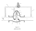
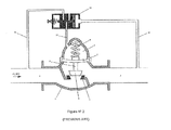
- a pilot operated pressure regulating valve is a mechanical device illustrated in Figure N°1 and in Figure N°2 , and comprises a body [1], an upstream inlet [2] and a downstream outlet [3].
- Both figures relates to the configuration known as pressure reducing valve.
- a seat [4] is provided over which a throttling element acts.
- This throttling element generally a plug [5] is attached by means of a stem [6] to an actuator [7]; this actuator moves the stem and the plug between totally open and totally closed positions of the valve.
- the actuator is a piston or a diaphragm as it is illustrated herein.
- the actuator isolates the upper part of the valve body generating a control chamber [8] where a spring is housed [9].
- Two-way regulating pilot [10] or three-way regulating pilot [11] are used to control the actuator of the pressure regulating valve in accordance with a control parameter; in this case, the downstream pressure value.
- the pilot is usually connected to the actuator of the valve by means of a pipe [21], through another pipe [20] the pilot is connected upstream of the valve [2] and through another pipe [19] the pilot is connected downstream [3] of the valve.
- the regulating pilot supplies controlled pressure within the chamber of the valve [8] through the pipe [21].
- This controlled pressure is what moves the actuator [7] from the totally open position, zero pressure within the chamber, to the totally closed position, maximum pressure within the chamber.
- the down force exerted by the spring [9] is added to the regulated pressure from the pipe [21] to the chamber [8] and they opposed to the pressure exerted by fluid over the lower portion of the actuator.
- pressure supplied by the pilot is the pressure which controls the position of the actuator, which in turn allows more or less fluid to flow, thereby regulating the pressure thereof.
- FIG. N°3 A typical model of a pilot known by those skilled in the art [10] is illustrated in Figure N°3 and it is known as a two-way pilot comprising: A body [12] with an inlet [13], an outlet [14] and a seat [15] between the inlet and outlet.
- the throttling element is secured by means of a vertical stem [17] to a horizontal flexible diaphragm [18].
- the diaphragm also called sensor, divides the body of the valve into a bottom portion where the fluid flows, and an upper portion which is isolated from fluid.
- a spring [23] which tension can be regulated through compression exerted thereon by a calibrated screw [24] is located in the upper portion of the valve, on top of the diaphragm and it is not in contact with fluid. The position of the screw sets the spring tension, and determines the target work pressure or set point (1).
- the outlet of the pilot is connected to fluid downstream of the pressure regulating valve through a pipe [19] so that the downstream pressure reaches the pilot exerting upward pressure against the flexible diaphragm.
- the inlet of the pilot is connected to fluid upstream of the pressure regulating valve through a pipe [20].
- a pipe [21] extends to the pressure regulating valve which supplies the control pressure for the actuator of the valve.
- the diaphragm [18] is pushed towards an open position which allows fluid to flow through the pilot or it is pushed towards a closed position which prevents fluid from flowing through the pilot.
- the spring pushes the flexible diaphragm down towards an open position and counteracts downstream pressure which pushes the diaphragm in the opposite direction, i.e, towards a closed position which restricts the flow of fluid through the seat of the pilot.
- FIG. N°4 Another typical model of a pilot of the previous art [11] known as a three-way pilot is illustrated en Figure N°4 and comprises: A vertical closed cylindrical body [36] having an upper hollow body portion, a bottom hollow body portion and a central solid body portion.
- the upper hollow body portion houses a spring [37] which tension can be regulated through the compression exerted thereon by a calibrated screw [24].
- the bottom hollow body portion houses a flexible diaphragm [25] located perpendicularly to the vertical shaft of the cylindrical body and having a lower outlet [26] connected to fluid downstream of the pressure regulating valve through a pipe [19].
- the central solid body portion [27] having a bore which extends longitudinally through its center from the bottom end to the upper end communicating the bottom hollow body portion with the upper hollow body portion.
- a shaft [28] is slideably housed inside that bore, the upper hollow portion of the shaft being attached to the spring [37] and the bottom hollow portion to the flexible diaphragm [25].
- This shaft is pressed down by the regulated pressure of the spring, also known as pressure set point.
- the same shaft is pulled up by the flexible diaphragm which receives downstream pressure.
- the shaft has a smaller diameter mid-section [29].
- the central solid body also has a central horizontal bore [30], perpendicular to the longitudinal shaft. This bore extends from the cylinder outside layer [31] to the shaft of the cylinder, and it is in communication with the longitudinal bore where the vertical shaft slides [28]. This central bore is in communication with the actuator of the pressure regulation valve by means of a pipe [21].
- the upper bore [33] is connected by means of a pipe [20] to the high pressure source at a point upstream of the pressure regulating valve.
- the other one, the lower bore [35] is connected to a low pressure source, which in this case is open to the atmosphere.
- the shaft slides up or down, making the central portion of this shaft, the one with reduced diameter, alternatively face the upper bore with high upstream pressure or the lower one without pressure which is connected to the atmosphere.
- Regulation is then achieved by temporarily exposing the chamber of the valve to a high pressure source or to a lower pressure source.
- Main advantages of pressure regulating pilots of the previous art include: relatively low cost, no external energy is required to operate, and the fact that inside a small and autonomous unit (2) a pressure sensor, set point controller and a valve are combined.
- a time pulse regulating pilot presents a solution to the problem of reliability and frequent maintenance required by today's pressure regulating pilots. It also allows the regulating pilot to communicate and interchange data with other remote processes and further includes the capability of the pilot to operate the pressure regulating valve as a cut-off or on-off valve.
- the pulse regulating pilot of this invention differs from the pilots of the previous art mainly because in order to control pressure in the valve chamber an electronic controller is used, such controller generates time pulses which open equal throttling elements which communicate the valve chamber with a high pressure source or with a low pressure source and this pilot does not utilize throttling elements, slideable shafts, or springs, or diaphragms. By not using these mechanical elements, maintenance decreases and reliability increases.
- Figure N° 5 relates to a pressure regulating valve of the configuration known as pressure reducing valve.
- the pilot operated pressure regulating valve comprises: a body [1], and upstream inlet [2] and a downstream inlet [3].
- a seat is provided [4] over which a throttling element acts.
- This throttling element generally a plug [5] is attached by means of a stem [6] to an actuator [7], this actuator moves the stem and the plug between the totally open and totally closed positions of the valve.
- the actuator is a piston o diaphragm as it is illustrated herein. The actuator isolates the upper portion of the valve body generating a control chamber [8] where a spring is housed [9].
- Pressure exerted inside the chamber [8] is what controls the movement of the actuator [7].
- the actuator in turn allows more or less fluid to flow through the seat [4], thereby increasing or reducing pressure downstream of the valve [3].
- the pulse regulating pilot [38] controls pressure inside the chamber [8] through a connecting pipe [21].
- the pulse pilot is connected to a high pressure source, which in this case is a point upstream of the valve [2] through a pipe [20], at a point where pressure wants to be controlled, in this case at a point downstream of the valve [3] by means of a piping [19] and to a low pressure source, in this case, the atmosphere, by means of the pipe [47].
- a high pressure source which in this case is a point upstream of the valve [2] through a pipe [20]
- a low pressure source in this case, the atmosphere, by means of the pipe [47].
- Figure N°6 depicts the components of the pulse regulating pilot [38]:
- An electronic controller [39] governs the operation of the pulse pilot.
- a transducer or pressure sensor [40] is in connection with a point where pressure wants to be controlled, in this case at a point downstream of the valve [3], through the pipe [19] and sends the controller an electrical signal proportional to the pressure measured in the pipe [19].
- An electronic controller is a device similar to a computer, and comprises a processor with programming, memory and math calculation capacity, and input and output units which communicate the processor with external elements such as sensors, transducers, analog ports, digital ports, serial ports, etc...
- a transducer or pressure sensor Figure N° 7 is generally a cylindrical device [61] which is screwed into the wall of the tank or pipe [56] with the fluid [57] to be measured
- a flexible membrane [58] isolates the inner portion of the fluid transducer.
- Membrane deformation under pressure actuates an inner mechanism [59] which generates an electrical or voltage signal which is proportional to the pressure exerted onto the membrane and travels from the transducer or sensor through the wire [60].
- Transducers may have different mechanisms including electromechanical, resistive, piezoelectric, piezoceramic or with semiconductors.
- a target pressure value also called pressure set point, reference, or order
- the information of a target pressure value is entered locally to the controller through keys or a regulating knob or screw [45], or the target pressure value can be received remotely through a an input and output communication port [46] as a data signal.
- An electrically actuated throttling element [41] closes the passage to the pipe [47] which communicates the low pressure source, in this case the atmosphere, with the chamber [8] through the pipe [21].
- This throttling element is generally closed, and it is open only when controller allows electrical current to power its driver. During the lapse of time it is open, the chamber of the valve [8] is temporarily exposed to the low pressure source, thereby reducing pressure inside the chamber.
- Another electrically actuated throttling element [42] closes the passage to the pipe [20] which communicates the high pressure source, in this case a point upstream of the valve [2] with the chamber [8] and the pipe [21].
- This throttling element is generally closed, and it is open only when controller allows electrical current to power its driver. During the lapse of time it is open, the chamber of the valve [8] is temporarily exposed to the high pressure source, thereby increasing pressure inside the chamber.
- the controller is powered by electric current from the power source [43], which may be autonomous with batteries or externally powered with energy through the connection [44]. This electric source maintains the operation of the controller and energizes the electric drivers of the throttling elements when the controller sends the order.
- the operation of the pulse regulating pilot starts with the input of the target value or pressure order by means of the device [45] or [46].
- the program installed in the controller waits a programmable lapse and it will read the pressure to be controlled via transducer [40], is this pressure is below pressure order or set point, the controller energizes thereby opening the throttling element [41] during a time pulse allowing the chamber [8] of the regulating valve to temporarily communicate with the atmosphere, thereby reducing pressure inside the chamber and the actuator [7] moves upwards moving the throttling element [5], thereby allowing more fluid to flow through the seat [4] and, consequently, increasing pressure downstream of the valve [3].
- the controller will wait again for the next programmable lapse to reed pressure of the transducer [40] and will adjust pressure by means of a new time pulse directed to the throttling element [41] if pressure is below the target pressure or, in turn, directed to the throttling element [42] if pressure read is above the target pressure or pressure order.
- the duration of time pulses generated by the controller is calculated by a control correction algorithm, such as proportional algorithm, derivative algorithm, proportional-integral-derivative algorithm, previously programmed in the controller.
- a control correction algorithm such as proportional algorithm, derivative algorithm, proportional-integral-derivative algorithm, previously programmed in the controller.
- Pressure order takes numerical value when pressure needs to be regulated to a determined value or may take a status value which can be open or closed.
- the controller When the open value is set, the controller will send multiple pulses to the throttling element [41] to leave the chamber [8] completely without pressure.
- close value When close value is set, the controller will send multiple pulses to the throttling element [42] to leave the chamber [8] totally pressurized thereby, closing the pressure regulating valve.
- the input and output communication port [46] allows data such as present pressure value, information about the open or closed status of the valve, or alarm signals to be sent to remote controllers of other processes.
- Figure N° 8 depicts an example of the application of a pulse pressure regulating pilot [38].
- the controller [39] of this example comprises a plate or electronic card [48] where the processor is mounted [49], in this case a Zilog Inc. Z180 (7) ; a controller to read 4 to 20 mA current normalized signal [50], a serial communication controller [51] for radio modem and two relay digital outputs, 12 VDC. [52] y [53].
- the power source [43] comprises a 7000 mAh, 12VDC dry battery available from EnerSys Inc. (8) with 12 volts - 2 watt solar plate charger [54].
- the sensor and pressure transducer [40] in this example is a model CTE/CTU8000 available from Sensortechnics GmbH (9) which converts fluid pressure into a signal proportional to a 4 and 20 mA current signal.
- a radio modem [55] model 9XStream available form Maxstream (10) allow wireless serial communication with a remote equipment and internal serial communication with the processor [49] through the serial communication driver [51].
- throttling elements are two 12 VDC, 2-way solenoid valves [41] and [42] generally closed, model 330 available from Burkert GmbH (11).
- the processor has a program which reads at a fixed frequency f1, the signal sent by pressure transducer [40].
- the program also reads at fixed frequency f2, generally below f1, the serial communication port [46] to update possible set point changes which are sent remotely. In the same port [46] at the same frequency, the program also writes present value provided by the pressure transducer. In this case, the local manual regulator [45] is not used since the order is sent remotely.
- the processor program [49] compares the pressure order value with transducer present pressure [40] and if the latter is lower, generates a time pulse which energizes the solenoid valve [41] through the first digital relay output. On the other hand, if the transducer present pressure [40] is higher, it generates a time pulse that now energizes the solenoid valve [42] through the second digital relay output. If the pressure order is equal to the present pressure, nothing is done and it waits until the next transducer reading [40].
- time pulses duration is fixed and corresponds to 200 milliseconds.
Landscapes
- Physics & Mathematics (AREA)
- Fluid Mechanics (AREA)
- General Physics & Mathematics (AREA)
- Engineering & Computer Science (AREA)
- Automation & Control Theory (AREA)
- Control Of Fluid Pressure (AREA)
Applications Claiming Priority (1)
| Application Number | Priority Date | Filing Date | Title |
|---|---|---|---|
| CL2008000317A CL2008000317A1 (es) | 2008-02-01 | 2008-02-01 | Piloto para valvula reguladora de presion que tiene una tuberia de comunicacion, entre la camara de la valvula y una fuente de presion alta, que esta interrumpida por un elemento de cierre con accionamiento electrico. |
Publications (2)
| Publication Number | Publication Date |
|---|---|
| EP2085852A2 true EP2085852A2 (de) | 2009-08-05 |
| EP2085852A3 EP2085852A3 (de) | 2010-11-24 |
Family
ID=40261172
Family Applications (1)
| Application Number | Title | Priority Date | Filing Date |
|---|---|---|---|
| EP20090151737 Withdrawn EP2085852A3 (de) | 2008-02-01 | 2009-01-30 | Zeitimpulssteuerventil für Druckregelventil |
Country Status (6)
| Country | Link |
|---|---|
| US (1) | US20090248210A1 (de) |
| EP (1) | EP2085852A3 (de) |
| AU (1) | AU2009200337A1 (de) |
| CL (1) | CL2008000317A1 (de) |
| PE (1) | PE20100132A1 (de) |
| ZA (1) | ZA200900765B (de) |
Cited By (3)
| Publication number | Priority date | Publication date | Assignee | Title |
|---|---|---|---|---|
| WO2018015002A1 (de) * | 2016-07-20 | 2018-01-25 | Lubing Maschinenfabrik | Druckminderer für tiertränken sowie verfahren zum verstellen mindestens eines druckminderers für tiertränken |
| FR3074928A1 (fr) * | 2017-12-08 | 2019-06-14 | Reda Al Bayaa | Appareil electronique de commande pour controler une vanne de base |
| EP3387508A4 (de) * | 2016-01-13 | 2019-08-21 | Honeywell International Inc. | Druckregler |
Families Citing this family (13)
| Publication number | Priority date | Publication date | Assignee | Title |
|---|---|---|---|---|
| JP5837521B2 (ja) * | 2013-01-30 | 2015-12-24 | Ckd株式会社 | 電空レギュレータ |
| CN103836240B (zh) * | 2014-02-26 | 2016-05-04 | 武汉第二船舶设计研究所 | 一种带有卸载装置的阀门 |
| CN105333183B (zh) * | 2015-11-19 | 2018-05-04 | 江西洪都航空工业集团有限责任公司 | 一种主动控制的安全阀 |
| DE202017101427U1 (de) * | 2017-03-13 | 2018-06-14 | Neoperl Gmbh | Durchflussmengenregler |
| US10940447B2 (en) * | 2017-06-30 | 2021-03-09 | Pulsair Systems, Inc. | Control circuit for stopping the flow of fluid in a primary circuit, and related methods and devices |
| CN110030425A (zh) * | 2019-05-17 | 2019-07-19 | 常熟市海舟电气有限公司 | 快速开盖泄压阀门 |
| EP3745007A1 (de) * | 2019-05-29 | 2020-12-02 | Microtecnica S.r.l. | Druckentlastungsventil |
| US11275393B2 (en) * | 2019-11-07 | 2022-03-15 | Pittway Sarl | Air spring pressure regulating valve |
| CN110886892B (zh) * | 2019-12-05 | 2021-05-04 | 江西洪都航空工业集团有限责任公司 | 一种电磁阀 |
| US20220146052A1 (en) * | 2020-11-06 | 2022-05-12 | Vrg Controls Llc | Monitor control valve with backflow prevention |
| US12372985B2 (en) * | 2020-11-06 | 2025-07-29 | VRG Controls, LLC | Monitor control valve with backflow prevention |
| JP7424322B2 (ja) * | 2021-01-19 | 2024-01-30 | Smc株式会社 | 流体圧力制御装置 |
| CN115234697B (zh) * | 2022-08-11 | 2023-10-13 | 苏州协昌环保科技股份有限公司 | 电磁脉冲阀 |
Citations (1)
| Publication number | Priority date | Publication date | Assignee | Title |
|---|---|---|---|---|
| US6178997B1 (en) | 1997-09-22 | 2001-01-30 | Fisher Controls International, Inc. | Intelligent pressure regulator |
Family Cites Families (16)
| Publication number | Priority date | Publication date | Assignee | Title |
|---|---|---|---|---|
| US3724485A (en) * | 1971-05-12 | 1973-04-03 | Servo Labs Inc | Flow controller |
| JPS587825B2 (ja) * | 1977-05-04 | 1983-02-12 | トヨタ自動車株式会社 | 内燃機関の燃料供給装置 |
| US4103710A (en) * | 1977-09-12 | 1978-08-01 | Baker International Corporation | Time cycle controller for pneumatic valve |
| US4462566A (en) * | 1982-02-08 | 1984-07-31 | French Bruce C | Pressure compensated flow control system |
| US4653274A (en) * | 1984-03-06 | 1987-03-31 | David Constant V | Method of controlling a free piston external combustion engine |
| US4762300A (en) * | 1985-02-19 | 1988-08-09 | Nippondenso Co., Ltd. | Control valve for controlling fluid passage |
| JP2658432B2 (ja) * | 1988-12-01 | 1997-09-30 | ダイキン工業株式会社 | 油圧制御装置 |
| DE3939002A1 (de) * | 1989-11-25 | 1991-05-29 | Bosch Gmbh Robert | Hydraulische ventilsteuervorrichtung fuer eine mehrzylinder-brennkraftmaschine |
| US5957393A (en) * | 1994-03-03 | 1999-09-28 | Nordson Corporation | Air regulator control system for powder coating operation |
| DE19782256T1 (de) * | 1997-02-06 | 2000-03-16 | Smc Kk | Pneumatischer Regler |
| AUPP639098A0 (en) * | 1998-10-08 | 1998-10-29 | Yudanov, Sergi | Hydraulically actuated electronically controlled fuel injection system |
| US6684853B1 (en) * | 1998-10-16 | 2004-02-03 | International Engine Intellectual Property Company, Llc | Fuel injector with direct needle valve control |
| US6591201B1 (en) * | 2000-09-28 | 2003-07-08 | Thomas Allen Hyde | Fluid energy pulse test system |
| US7020551B2 (en) * | 2003-12-23 | 2006-03-28 | Bendix Commercial Vehicle Systems Llc | Roll stability control system |
| US20090114396A1 (en) * | 2007-11-05 | 2009-05-07 | David John Kusko | Wellsite measurement and control while producing device |
| US20110005250A1 (en) * | 2009-07-09 | 2011-01-13 | Perz Alfred F | Switching pressure regulator |
-
2008
- 2008-02-01 CL CL2008000317A patent/CL2008000317A1/es unknown
-
2009
- 2009-01-30 EP EP20090151737 patent/EP2085852A3/de not_active Withdrawn
- 2009-01-30 PE PE2009000139A patent/PE20100132A1/es not_active Application Discontinuation
- 2009-01-30 US US12/362,785 patent/US20090248210A1/en not_active Abandoned
- 2009-01-30 AU AU2009200337A patent/AU2009200337A1/en not_active Abandoned
- 2009-02-02 ZA ZA200900765A patent/ZA200900765B/en unknown
Patent Citations (1)
| Publication number | Priority date | Publication date | Assignee | Title |
|---|---|---|---|---|
| US6178997B1 (en) | 1997-09-22 | 2001-01-30 | Fisher Controls International, Inc. | Intelligent pressure regulator |
Cited By (4)
| Publication number | Priority date | Publication date | Assignee | Title |
|---|---|---|---|---|
| EP3387508A4 (de) * | 2016-01-13 | 2019-08-21 | Honeywell International Inc. | Druckregler |
| WO2018015002A1 (de) * | 2016-07-20 | 2018-01-25 | Lubing Maschinenfabrik | Druckminderer für tiertränken sowie verfahren zum verstellen mindestens eines druckminderers für tiertränken |
| US10768643B2 (en) | 2016-07-20 | 2020-09-08 | Lubing Maschinenfabrik Ludwig Bening Gmbh & Co. Kg | Pressure reducer for animal drinking troughs, and method for adjusting at least one pressure reducer for animal drinking troughs |
| FR3074928A1 (fr) * | 2017-12-08 | 2019-06-14 | Reda Al Bayaa | Appareil electronique de commande pour controler une vanne de base |
Also Published As
| Publication number | Publication date |
|---|---|
| AU2009200337A1 (en) | 2009-08-20 |
| CL2008000317A1 (es) | 2008-03-28 |
| ZA200900765B (en) | 2009-12-30 |
| EP2085852A3 (de) | 2010-11-24 |
| US20090248210A1 (en) | 2009-10-01 |
| PE20100132A1 (es) | 2010-02-20 |
Similar Documents
| Publication | Publication Date | Title |
|---|---|---|
| US20090248210A1 (en) | Time pulse pilot for pressure regulating control valve | |
| CN105849449B (zh) | 阀和操作阀的方法 | |
| CA2469838A1 (en) | Water supply system | |
| MX2021011942A (es) | Elemento de potencia para valvula moduladora de refrigerante. | |
| US10605274B2 (en) | Valve arrangement | |
| US20100051110A1 (en) | Gas actuated valve | |
| WO2017083474A1 (en) | Pipeline-waste-gas reduction method | |
| US12578020B2 (en) | Inlet controlled regulating valve | |
| EP4524520A2 (de) | Dosierdruckregelventil | |
| CN107061757B (zh) | 独立控制旋转阀中的落座力的方法和装置 | |
| US8418770B2 (en) | Multi-process electronic control valve system | |
| EP1375990A1 (de) | Magnetventil | |
| US20150152973A1 (en) | Piezo-actuated pilot valve | |
| CN109869363B (zh) | 一种液压智能控制阀 | |
| US9977437B1 (en) | Pilot operated parallel valve | |
| US20110192999A1 (en) | Gas pressure regulator with integrated remote disconnect | |
| EP3022448B1 (de) | Diskrete vorsteuerstufenventilanordnung mit fail-freeze-modus | |
| RU2685167C1 (ru) | Адаптивный пневматический привод с обратной пневматической связью | |
| RU2554536C2 (ru) | Способ и устройство для соединения электропневматического контроллера с преобразователем положения в системе управления технологическим процессом | |
| US11275393B2 (en) | Air spring pressure regulating valve | |
| RU2262731C2 (ru) | Устройство автоматического регулирования | |
| CA3147745C (en) | Meters having integrated pressure regulators and related methods and systems | |
| RU62657U1 (ru) | Устройство для дистанционного управления скважинами куста | |
| EP3702872A1 (de) | Druckunabhängiges regelventil | |
| RU118083U1 (ru) | Поршневой регулятор давления газа |
Legal Events
| Date | Code | Title | Description |
|---|---|---|---|
| PUAI | Public reference made under article 153(3) epc to a published international application that has entered the european phase |
Free format text: ORIGINAL CODE: 0009012 |
|
| AK | Designated contracting states |
Kind code of ref document: A2 Designated state(s): AT BE BG CH CY CZ DE DK EE ES FI FR GB GR HR HU IE IS IT LI LT LU LV MC MK MT NL NO PL PT RO SE SI SK TR |
|
| AX | Request for extension of the european patent |
Extension state: AL BA RS |
|
| PUAL | Search report despatched |
Free format text: ORIGINAL CODE: 0009013 |
|
| AK | Designated contracting states |
Kind code of ref document: A3 Designated state(s): AT BE BG CH CY CZ DE DK EE ES FI FR GB GR HR HU IE IS IT LI LT LU LV MC MK MT NL NO PL PT RO SE SI SK TR |
|
| AX | Request for extension of the european patent |
Extension state: AL BA RS |
|
| 17P | Request for examination filed |
Effective date: 20110524 |
|
| AKX | Designation fees paid |
Designated state(s): AT BE BG CH CY CZ DE DK EE ES FI FR GB GR HR HU IE IS IT LI LT LU LV MC MK MT NL NO PL PT RO SE SI SK TR |
|
| 17Q | First examination report despatched |
Effective date: 20110907 |
|
| STAA | Information on the status of an ep patent application or granted ep patent |
Free format text: STATUS: THE APPLICATION IS DEEMED TO BE WITHDRAWN |
|
| 18D | Application deemed to be withdrawn |
Effective date: 20120320 |