EP2085997A2 - Appareil de contrôle de charge - Google Patents
Appareil de contrôle de charge Download PDFInfo
- Publication number
- EP2085997A2 EP2085997A2 EP09150912A EP09150912A EP2085997A2 EP 2085997 A2 EP2085997 A2 EP 2085997A2 EP 09150912 A EP09150912 A EP 09150912A EP 09150912 A EP09150912 A EP 09150912A EP 2085997 A2 EP2085997 A2 EP 2085997A2
- Authority
- EP
- European Patent Office
- Prior art keywords
- temperature
- control apparatus
- electric conductor
- current circuit
- conductor element
- Prior art date
- Legal status (The legal status is an assumption and is not a legal conclusion. Google has not performed a legal analysis and makes no representation as to the accuracy of the status listed.)
- Withdrawn
Links
Images

Classifications
-
- H—ELECTRICITY
- H02—GENERATION; CONVERSION OR DISTRIBUTION OF ELECTRIC POWER
- H02H—EMERGENCY PROTECTIVE CIRCUIT ARRANGEMENTS
- H02H3/00—Emergency protective circuit arrangements for automatic disconnection directly responsive to an undesired change from normal electric working condition with or without subsequent reconnection ; integrated protection
- H02H3/08—Emergency protective circuit arrangements for automatic disconnection directly responsive to an undesired change from normal electric working condition with or without subsequent reconnection ; integrated protection responsive to excess current
-
- H—ELECTRICITY
- H01—ELECTRIC ELEMENTS
- H01H—ELECTRIC SWITCHES; RELAYS; SELECTORS; EMERGENCY PROTECTIVE DEVICES
- H01H37/00—Thermally-actuated switches
- H01H37/002—Thermally-actuated switches combined with protective means
-
- H—ELECTRICITY
- H01—ELECTRIC ELEMENTS
- H01H—ELECTRIC SWITCHES; RELAYS; SELECTORS; EMERGENCY PROTECTIVE DEVICES
- H01H61/00—Electrothermal relays
- H01H61/02—Electrothermal relays wherein the thermally-sensitive member is heated indirectly, e.g. resistively, inductively
-
- H—ELECTRICITY
- H02—GENERATION; CONVERSION OR DISTRIBUTION OF ELECTRIC POWER
- H02H—EMERGENCY PROTECTIVE CIRCUIT ARRANGEMENTS
- H02H5/00—Emergency protective circuit arrangements for automatic disconnection directly responsive to an undesired change from normal non-electric working conditions with or without subsequent reconnection
- H02H5/04—Emergency protective circuit arrangements for automatic disconnection directly responsive to an undesired change from normal non-electric working conditions with or without subsequent reconnection responsive to abnormal temperature
Definitions
- the invention relates to a load control apparatus adapted to indirectly detect an overcurrent occurring in an electric conductor element belonging to a load current circuit on the basis of an increase in temperature.
- a known load control apparatus capable of detecting an overcurrent comprises a temperature sensor for each controlled electric conductor element of the load current circuit.
- the load control apparatus comprises an electronics circuit including a signal input terminal for each temperature sensor.
- the load control apparatus calculates the temperature corresponding to the output signal of each temperature sensor, and detects any overcurrent on the basis of an increase in temperature.
- the object of the invention is to provide a load control apparatus for solving the above problems.
- the object of the invention is achieved with a load control apparatus characterized in what is stated in independent claim 1. Preferred embodiments of the invention are described in the dependent claims.
- the invention is based on detecting an overcurrent by means of a change in the operational state of a temperature-sensitive switch member connected heat-conductively to the load circuit being controlled but electrically isolated therefrom.
- the load control apparatus of the invention is its simplicity and inexpensive manufacturing costs. These advantages are emphasized in embodiments wherein the load control apparatus comprises a plurality of series-connected, normally closed-type temperature-sensitive switch members, each of which is connected to one controlled point of the load, whereby an overcurrent occurring in any controlled point of the load can be detected by observing the opening of the control current circuit comprising the series-connected temperature-sensitive switch members.
- the temperature-sensitive switch member of the load control apparatus of the invention is not part of the load current circuit, the detection of an overcurrent by means of a change in the operational state of the temperature-sensitive switch member does not interfere in any way with the operation of the load current circuit. Furthermore, since the temperature-sensitive switch member is not part of the load current circuit, it does not have to be designed to endure currents occurring in the load current circuit.
- FIG. 1 shows a simplified connection diagram of a load control apparatus 30, adapted to indirectly detect an overcurrent occurring in a electric conductor element 4 belonging to a load current circuit 20.
- the load control apparatus 30 comprises a control unit 32 and a temperature-sensitive switch member S.
- the temperature-sensitive switch member S is capable of changing its operational state in response to an increase in the temperature to a predetermined value.
- the temperature-sensitive switch member S is part of a control current circuit electrically connected to the control unit 32.
- the control unit 32 is adapted to detect whether the control current circuit is open or closed.
- the temperature-sensitive switch member S is connected heat-conductively to the electric conductor element 4.
- the heat-conductive connection is denoted with a rectangle 6 drawn with a dotted line.
- the electric conductor element 4 and the temperature-sensitive switch member S are electrically isolated from one another.
- the type of the temperature-sensitive switch member S may be a normally closed type of switch member. This being so, an overcurrent occurring in the electric conductor element 4 increases the temperature of the electric conductor element 4, and the increase in the temperature is transmitted via the heat-conductive connection 6 to the temperature-sensitive switch member S.
- the heating of the temperature-sensitive switch member S changes the operational state of the temperature-sensitive switch member from closed into open, opening the control current circuit.
- the control unit 32 detects the opening of the control current circuit, and thus detects the overcurrent occurring in the electric conductor element 4.
- the type of the temperature-sensitive switch member S may be a normally open type of switch member. This being so, an increase in the temperature changes the operational state of the temperature-sensitive switch member from open into closed, closing the control current circuit.
- the control unit 32 detects the overcurrent based on the closing of the control current circuit.
- the load current circuit includes a power source PS that is loaded with a load impedance Z L .
- the electric conductor element 4 conveys load current between the power source PS and the load impedance Z L .
- the load control apparatus shown in Figure 2 is similar to the load control apparatus shown in Figure 1 , except for a thermistor member R th that is connected in series with the electric conductor element 4.
- the type of the thermistor member R th is a PTC thermistor, whose resistance increases as its temperature increases.
- the thermistor member R th is connected heat-conductively to the temperature-sensitive switch member S.
- the thermistor member R th Since the thermistor member R th is connected electrically in series with the electric conductor element 4, the same current passes through the thermistor member R th as through the load impedance Z L .
- the thermistor member R th improves the sensitivity of the load control apparatus to an overcurrent, since, as the current passing through the thermistor member R th increases, the resistance of the thermistor member R th increases, and thus more heat than previously is also generated in the thermistor member R th , to which the temperature-sensitive switch member S reacts.
- the load control apparatus may comprise, per each controlled electric conductor element, a thermistor assembly adapted to be connected heat-conductively to said electric conductor element of the load current circuit.
- the thermistor assembly is adapted to be connected heat-conductively to the temperature-sensitive switch member for detecting a temperature change caused by an overcurrent in the thermistor assembly.
- the thermistor assembly may comprise a plurality of thermistor members, which may comprise PTC thermistors and NTC thermistors.
- the thermistor assembly may comprise one or more thermistor members adapted to be connected in parallel with the controlled electric conductor element of the load current circuit.
- the thermistor assembly is adapted such that the temperature-sensitive switch member reacts in the desired manner to an overcurrent in the electric conductor element of the load current circuit.
- a PTC thermistor refers generally to a component whose resistance increases more steeply due to its temperature rise than the resistance of the electric conductor element of the load current circuit.
- Figure 3 shows a rectifier assembly comprising a six-pulse bridge 16 and a load control apparatus adapted to monitor currents of the six-pulse bridge.
- the six-pulse bridge 16 comprises two parallel diode branches for increasing the current/power capacity. Accordingly, the six-pulse bridge 16 comprises twelve diodes in total.
- Phase U of the power source is connected to the six-pulse bridge 16 via electric conductor elements U 1 and U 2
- phase V of the power source is connected to the six-pulse bridge 16 via electric conductor elements V 1 and V 2
- phase W of the power source is connected to the six-pulse bridge 16 via electric conductor elements W 1 and W 2 .
- the rectifier assembly comprises six thermistor members R th,U1 , R th,V1 , R th,W1 , R th,U2 , R th,V2 , and R th,W2 , each of which is connected in series with a corresponding electric conductor element.
- the load current circuit comprises a fuse connected in series with each thermistor member such that fuses FS U1 , FS V1 , FS W1 , FS U2 , FS V2 and FS W2 are connected in series with thermistor members R th,U1 , R th,V1 , R th,W1 , R th,U2 , R th,V2 , and R th,W2 , respectively.
- the control current circuit connected to the control unit 32 includes six normally closed-type temperature-sensitive switch members S U1 , S V1 , S W1 , S U2 , S V2 and S W2 , connected in series.
- the temperature-sensitive switch members S U1 , S V1 , S W1 , S U2 , S V2 and S W2 are connected heat-conductively to thermistor members R th,U1 , R th,V1 , R th,W1 , R th,U2 , R th,V2 , and R th,W2 , correspondingly.
- An increase in the temperature of any of the temperature-sensitive switch members of the control current circuit opens said temperature-sensitive switch member and, thus, the entire control current circuit. For example, if the fuse FS W2 of electric conductor element W 2 blows, the load current of phase W starts to pass entirely via electric conductor element W1, which causes an overcurrent in electric conductor element W1. An overcurrent occu r-ring in electric conductor element W1 increases the temperature of electric conductor element W1, resulting in an increase also in the temperature of temperature-sensitive switch member S W1 .
- the temperature-sensitive switch member S W1 opens when its temperature rises to a predetermined value, whereby also the control current circuit opens, and the control unit 32 detects the overcurrent occurring in the load current circuit.
- the bridge controlled with the load control apparatus shown in Figure 3 may be, instead of a diode bridge, a semi-controlled or a fully controlled bridge, and that the bridge may be of another type than a six-pulse bridge. It is also obvious that the bridge to be controlled may be part of a broader entity.
- the bridge to be controlled may be, for instance, a rectifier bridge belonging to the rectifier unit of a frequency converter assembly or an inverter bridge belonging to an inverter unit of a frequency converter assembly.
- the load control apparatus of the invention may be used for the control of other types of load current circuits than bridge connections.
- a temperature-sensitive switch member may be connected heat-conductively to the electric conductor element of the load current circuit or to a thermistor member or thermistor assembly connected conductively to an electric conductor element.
- the temperature-sensitive switch member of the load control apparatus of the invention may be adapted to be connected heat-conductively to any target element in which at least part of the load current of the electric conductor element of the load current circuit passes in an operating situation.
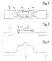
- Figure 4 shows an assembly belonging to a load control apparatus according to an embodiment of the invention and including a narrowing member 14 and a temperature-sensitive switch element S connected thereto.
- the narrowing member 14 is adapted to be connected in series with an electric conductor element of the load current circuit, whereby the same current passes through the narrowing member 14 in an operating situation as does through the electric conductor element of the load current circuit.
- the cross-sectional area of the narrowing member 14 in the axial ends thereof is the same as the cross-sectional area of that electric conductor element of the load current circuit, with which the narrowing member 14 is adapted to be connected in series. Between its axial ends, the narrowing member 14 comprises three narrowing portions nw1, nw2 and nw3, whose width is smaller than the width of the narrowing member 14 at the axial ends.
- the task of the narrowing member 14 is similar to that of the PTC thermistor to be connected in series with the load current circuit, i.e. to improve the sensitivity of the load control apparatus to overcurrent.
- the narrowing member 14 heats more strongly than the electric conductor element of the load current circuit connected in series therewith, and therefore the temperature-sensitive switch member S connected heat-conductively to the narrowing member 14 reacts more sensitively to overcurrent than a corresponding temperature-sensitive switch member connected heat-conductively to the electric conductor element.
- the temperature-sensitive switch member S is connected heat-conductively onto the midmost narrowing portion nw2 such that the midpoint cp of the temperature-sensitive switch member S is on top of the midmost narrowing portion nw2.
- an electrical insulating member 8 that electrically insulates the temperature-sensitive switch member S from the narrowing member 14, whereby the temperature-sensitive switch member S is electrically insulated also from the load current circuit in an operating situation.
- the electrical insulating member is adapted to conduct heat well from a target element to the temperature-sensitive switch member.
- the electrical insulating member may comprise one or more material layers, each of which is of a well heat conductive solid or fluid material.
- the electrical insulating member 8 is fixed to the narrowing member 14 with two fastening members 10, which may be screws, for example.
- the fastening between the temperature-sensitive switch member S and the electrical insulating member 8 may comprise a well heat conductive adhesive layer, for example.
- Figure 5 shows a cross-section of the assembly of Figure 4 taken along the midline A - B of the narrowing member.
- Figure 5 shows that the narrowing member 14 comprises, between its axial ends, a portion whose thickness is smaller than the thickness of the narrowing member 14 in the axial ends.
- thickness refers to that dimension of the narrowing member 14, which is perpendicular to both the axial direction and the lateral direction.
- the portion having a decreased thickness extends over the narrowing portions nw1, nw2 and nw3 such that both the width and the thickness of the narrowing portions are smaller than the corresponding dimensions of the axial ends of the narrowing member 14.
- Figure 5 shows that there is no air gap between the temperature-sensitive switch member S and the narrowing member 14 in the radial direction.
- a radial direction refers to the direction perpendicular with respect to the current passing in the narrowing member in an operating situation. Since there is no air gap in the radial direction between the temperature-sensitive switch member S and the narrowing member 14, which is conducting in an operating situation, heat is conducted efficiently from the narrowing member 14 to the temperature-sensitive switch member S, thus enabling a rapid reaction of the temperature-sensitive switch member S to an overcurrent occurring in the narrowing member 14.
- Figure 6 shows the temperature distribution occurring in the narrowing member 14 of the assembly of Figure 4 .
- the horizontal axis x corresponds to the distance from the axial end of the narrowing member viewed along midline A - B.
- the vertical axis T corresponds to temperature.
- Figure 6 shows that the hottest point of the narrowing member 14 is situated at the midpoint cp of the temperature-sensitive switch member S.
- the narrowing member of the load control apparatus may be made from the same material as the electric conductor element with which the narrowing member is adapted to be connected in series.
- the narrowing member may be made from a material whose resistance increases as a function of temperature more steeply than the resistance of the electric conductor element, whereby the narrowing member is heated still more strongly under the influence of an overcurrent. Accordingly, the narrowing member may also serve as a PTC thermistor member.
- the narrowing member may be connected to the electric conductor element of a load current circuit by soldering or with a bolt joint, for example.
- the narrowing member may be integrated into the electric conductor element.
- the narrowing member may be achieved by arranging one or more narrowing portions in the electric conductor element of the load current circuit, such as a busbar, for example. Accordingly, the narrowing portion may also be retrofitted in the electric conductor element of the load current circuit for instance by cutting off pieces from the busbar of the load current circuit.
- overcurrent refers to a current magnitude that exceeds a predetermined limit value. Accordingly, an overcurrent does not have to be the highest allowable current of a load current circuit or a component thereof, but an overcurrent may be any exceeding of a limit value of interest to a user.
Landscapes
- Emergency Protection Circuit Devices (AREA)
Applications Claiming Priority (1)
| Application Number | Priority Date | Filing Date | Title |
|---|---|---|---|
| FI20085063A FI120926B (fi) | 2008-01-25 | 2008-01-25 | Kuormituksenvalvontalaitteisto |
Publications (3)
| Publication Number | Publication Date |
|---|---|
| EP2085997A2 true EP2085997A2 (fr) | 2009-08-05 |
| EP2085997A9 EP2085997A9 (fr) | 2009-10-07 |
| EP2085997A3 EP2085997A3 (fr) | 2013-07-17 |
Family
ID=39004363
Family Applications (1)
| Application Number | Title | Priority Date | Filing Date |
|---|---|---|---|
| EP09150912.5A Withdrawn EP2085997A3 (fr) | 2008-01-25 | 2009-01-20 | Appareil de contrôle de charge |
Country Status (4)
| Country | Link |
|---|---|
| US (1) | US8139338B2 (fr) |
| EP (1) | EP2085997A3 (fr) |
| CN (1) | CN101494371B (fr) |
| FI (1) | FI120926B (fr) |
Cited By (1)
| Publication number | Priority date | Publication date | Assignee | Title |
|---|---|---|---|---|
| US20220166208A1 (en) * | 2020-11-23 | 2022-05-26 | Shenzhen Smoore Technology Limited | Controlling device and electronic atomization device |
Families Citing this family (6)
| Publication number | Priority date | Publication date | Assignee | Title |
|---|---|---|---|---|
| FI120926B (fi) * | 2008-01-25 | 2010-04-30 | Abb Oy | Kuormituksenvalvontalaitteisto |
| CN103022961B (zh) * | 2011-09-22 | 2016-04-27 | 瑞侃电子(上海)有限公司 | 电路保护器件、包含该器件的电子电路及电路保护方法 |
| DE202017106035U1 (de) | 2017-10-04 | 2019-01-10 | Tmc Sensortechnik Gmbh | Elektrischer Netzstecker |
| JP6615951B2 (ja) * | 2018-07-06 | 2019-12-04 | デクセリアルズ株式会社 | スイッチ素子、スイッチ回路、及び警報回路 |
| CN108879615A (zh) * | 2018-07-11 | 2018-11-23 | 佛山市众盈电子有限公司 | 一种过流保护电路 |
| CN110350487B (zh) * | 2019-06-19 | 2022-09-13 | 安徽沃博源科技有限公司 | 一种电池模组的电路保护装置及方法 |
Family Cites Families (24)
| Publication number | Priority date | Publication date | Assignee | Title |
|---|---|---|---|---|
| US3482146A (en) * | 1966-12-28 | 1969-12-02 | Texas Instruments Inc | Overload and heat protective apparatus for three-phase motors |
| US3614345A (en) * | 1969-11-17 | 1971-10-19 | Zyrotron Ind Inc | Thermal sensing device |
| US3840834A (en) * | 1972-12-18 | 1974-10-08 | Texas Instruments Inc | Protector/indicator using ptc heater and thermostatic bimetal combination |
| US3857068A (en) | 1973-09-26 | 1974-12-24 | Westinghouse Electric Corp | Transformer having a thyristor controlled circuit breaker |
| EP0062082A1 (fr) * | 1981-04-03 | 1982-10-13 | Pai I. Kuo | Résistance de sécurité thermosensible |
| JPH0622392Y2 (ja) | 1986-02-21 | 1994-06-15 | 株式会社ニッコー | バッテリ駆動玩具の電源装置 |
| DE3843277A1 (de) | 1988-12-22 | 1990-06-28 | Bosch Gmbh Robert | Leistungsendstufe fuer elektromagnetische verbraucher |
| DE3924465A1 (de) | 1989-07-24 | 1991-02-07 | Siemens Ag | Temperaturueberwachungsvorrichtung fuer eine elektrische sicherung |
| AT394914B (de) | 1990-10-25 | 1992-07-27 | Electrovac | Thermischer schalter |
| DE4300909C2 (de) * | 1993-01-15 | 1997-02-06 | Abb Patent Gmbh | Thermischer Auslöser, insbesondere für einen Leitungsschutzschalter |
| JPH06260067A (ja) * | 1993-03-01 | 1994-09-16 | Matsushita Electric Ind Co Ltd | 温度ヒューズ取付装置 |
| JP3056922B2 (ja) | 1993-09-30 | 2000-06-26 | 株式会社東芝 | 自動製氷装置 |
| US5590010A (en) * | 1994-07-12 | 1996-12-31 | Ceola; Giacomo | Heat responsive power interrupting device |
| GB9417376D0 (en) | 1994-08-25 | 1994-10-19 | Melton David L | Remote isolation plug |
| US5666272A (en) * | 1994-11-29 | 1997-09-09 | Sgs-Thomson Microelectronics, Inc. | Detachable module/ball grid array package |
| JPH08294135A (ja) | 1995-04-20 | 1996-11-05 | Murata Mfg Co Ltd | 消磁回路及び電流制限装置 |
| US5801914A (en) * | 1996-05-23 | 1998-09-01 | Sunbeam Products, Inc. | Electrical safety circuit with a breakable conductive element |
| JP3242863B2 (ja) * | 1997-06-10 | 2001-12-25 | 矢崎総業株式会社 | 温度ヒューズ |
| JP2001176371A (ja) | 1999-12-17 | 2001-06-29 | Fuji Electric Co Ltd | 熱動形過負荷検出装置 |
| JP2003324179A (ja) | 2002-05-02 | 2003-11-14 | Mitsubishi Electric Corp | 半導体装置 |
| US7446643B2 (en) * | 2004-11-23 | 2008-11-04 | The Hong Kong Polytechnic University | Resetable over-current and/or over-temperature protection system |
| WO2007120914A2 (fr) | 2006-04-17 | 2007-10-25 | Kopelman Robert Z | Prévention électrique des incendies |
| FI120926B (fi) * | 2008-01-25 | 2010-04-30 | Abb Oy | Kuormituksenvalvontalaitteisto |
| US8773827B2 (en) * | 2008-02-19 | 2014-07-08 | Simply Automated Incorporated | Intelligent circuit breaker apparatus and methods |
-
2008
- 2008-01-25 FI FI20085063A patent/FI120926B/fi active IP Right Grant
-
2009
- 2009-01-20 EP EP09150912.5A patent/EP2085997A3/fr not_active Withdrawn
- 2009-01-22 US US12/357,800 patent/US8139338B2/en active Active
- 2009-01-23 CN CN200910008464.6A patent/CN101494371B/zh active Active
Cited By (2)
| Publication number | Priority date | Publication date | Assignee | Title |
|---|---|---|---|---|
| US20220166208A1 (en) * | 2020-11-23 | 2022-05-26 | Shenzhen Smoore Technology Limited | Controlling device and electronic atomization device |
| US12100944B2 (en) * | 2020-11-23 | 2024-09-24 | Shenzhen Smoore Technology Limited | Controlling device and electronic atomization device |
Also Published As
| Publication number | Publication date |
|---|---|
| CN101494371B (zh) | 2015-02-04 |
| EP2085997A3 (fr) | 2013-07-17 |
| US8139338B2 (en) | 2012-03-20 |
| US20090190281A1 (en) | 2009-07-30 |
| CN101494371A (zh) | 2009-07-29 |
| FI20085063L (fi) | 2009-07-26 |
| FI20085063A0 (fi) | 2008-01-25 |
| EP2085997A9 (fr) | 2009-10-07 |
| FI120926B (fi) | 2010-04-30 |
Similar Documents
| Publication | Publication Date | Title |
|---|---|---|
| US8139338B2 (en) | Load control apparatus | |
| KR101904578B1 (ko) | 부하를 보호하기 위한 장치 및 방법 | |
| CN104332954B (zh) | 用于对电机进行热保护及功率调节的电路 | |
| GB2520495A (en) | Solid state power controller for an aircraft | |
| CN107466424B (zh) | 功率模块 | |
| JP2001520436A (ja) | ヒューズ素子を作動する回路装置および方法 | |
| US11302504B2 (en) | Fuse control system and method using defective mode detection | |
| US10615736B2 (en) | Temperature monitoring | |
| US9025292B2 (en) | Apparatus and method for the intelligent protection of an electrical lead | |
| EP1993195B1 (fr) | Ensemble de convertisseur de fréquence chauffée | |
| US6570129B1 (en) | Protection device for dual stage power supply | |
| US9325165B2 (en) | Device and method for protecting a consumer | |
| US8405430B2 (en) | Circuit configuration for protecting a circuit element having overcurrent and overtemperature detection | |
| US9520707B2 (en) | Device for protecting a user | |
| FI96997C (fi) | Elektroninen lämpörele | |
| US7116110B1 (en) | Sensorless protection for electronic device | |
| JPH1197215A (ja) | バリスタおよびバリスタ内蔵電源装置 | |
| EP2587604A1 (fr) | Dispositif de protection contre les défauts | |
| GB2028607A (en) | Heating circuits | |
| CN101507073A (zh) | 用于装置(尤其是电动机)的热过载保护电路 | |
| US20200266619A1 (en) | Refrigeration And/Or Freezing Appliance | |
| KR100829183B1 (ko) | 유도가열장치 | |
| CN120150528A (zh) | 整流器电路的运行方法、整流器控制单元及整流器组件 | |
| GB2186134A (en) | Heating circuits with protective arrangements | |
| JP5450988B2 (ja) | 過電流制限回路 |
Legal Events
| Date | Code | Title | Description |
|---|---|---|---|
| PUAI | Public reference made under article 153(3) epc to a published international application that has entered the european phase |
Free format text: ORIGINAL CODE: 0009012 |
|
| AK | Designated contracting states |
Kind code of ref document: A2 Designated state(s): AT BE BG CH CY CZ DE DK EE ES FI FR GB GR HR HU IE IS IT LI LT LU LV MC MK MT NL NO PL PT RO SE SI SK TR |
|
| AX | Request for extension of the european patent |
Extension state: AL BA RS |
|
| PUAL | Search report despatched |
Free format text: ORIGINAL CODE: 0009013 |
|
| RIC1 | Information provided on ipc code assigned before grant |
Ipc: H01H 61/02 20060101ALI20130606BHEP Ipc: H01H 37/00 20060101AFI20130606BHEP |
|
| AK | Designated contracting states |
Kind code of ref document: A3 Designated state(s): AT BE BG CH CY CZ DE DK EE ES FI FR GB GR HR HU IE IS IT LI LT LU LV MC MK MT NL NO PL PT RO SE SI SK TR |
|
| AX | Request for extension of the european patent |
Extension state: AL BA RS |
|
| 17P | Request for examination filed |
Effective date: 20131104 |
|
| RBV | Designated contracting states (corrected) |
Designated state(s): AT BE BG CH CY CZ DE DK EE ES FI FR GB GR HR HU IE IS IT LI LT LU LV MC MK MT NL NO PL PT RO SE SI SK TR |
|
| AKX | Designation fees paid |
Designated state(s): AT BE BG CH CY CZ DE DK EE ES FI FR GB GR HR HU IE IS IT LI LT LU LV MC MK MT NL NO PL PT RO SE SI SK TR |
|
| 17Q | First examination report despatched |
Effective date: 20151126 |
|
| STAA | Information on the status of an ep patent application or granted ep patent |
Free format text: STATUS: THE APPLICATION IS DEEMED TO BE WITHDRAWN |
|
| 18D | Application deemed to be withdrawn |
Effective date: 20160407 |