EP2086099A2 - Contrôleur pour une utilisation dans un convertisseur résonant de courant continu/courant continu - Google Patents
Contrôleur pour une utilisation dans un convertisseur résonant de courant continu/courant continu Download PDFInfo
- Publication number
- EP2086099A2 EP2086099A2 EP08160832A EP08160832A EP2086099A2 EP 2086099 A2 EP2086099 A2 EP 2086099A2 EP 08160832 A EP08160832 A EP 08160832A EP 08160832 A EP08160832 A EP 08160832A EP 2086099 A2 EP2086099 A2 EP 2086099A2
- Authority
- EP
- European Patent Office
- Prior art keywords
- direct current
- width modulation
- pulse width
- signal
- resonant
- Prior art date
- Legal status (The legal status is an assumption and is not a legal conclusion. Google has not performed a legal analysis and makes no representation as to the accuracy of the status listed.)
- Withdrawn
Links
- 230000002194 synthesizing effect Effects 0.000 claims abstract description 14
- 230000000630 rising effect Effects 0.000 claims description 4
- 230000015572 biosynthetic process Effects 0.000 claims description 3
- 238000003786 synthesis reaction Methods 0.000 claims description 3
- 238000010586 diagram Methods 0.000 description 4
- 230000001360 synchronised effect Effects 0.000 description 3
- 230000007423 decrease Effects 0.000 description 2
- 230000003213 activating effect Effects 0.000 description 1
- 239000003990 capacitor Substances 0.000 description 1
- 230000003247 decreasing effect Effects 0.000 description 1
Images

Classifications
-
- H—ELECTRICITY
- H02—GENERATION; CONVERSION OR DISTRIBUTION OF ELECTRIC POWER
- H02M—APPARATUS FOR CONVERSION BETWEEN AC AND AC, BETWEEN AC AND DC, OR BETWEEN DC AND DC, AND FOR USE WITH MAINS OR SIMILAR POWER SUPPLY SYSTEMS; CONVERSION OF DC OR AC INPUT POWER INTO SURGE OUTPUT POWER; CONTROL OR REGULATION THEREOF
- H02M3/00—Conversion of DC power input into DC power output
- H02M3/22—Conversion of DC power input into DC power output with intermediate conversion into AC
- H02M3/24—Conversion of DC power input into DC power output with intermediate conversion into AC by static converters
- H02M3/28—Conversion of DC power input into DC power output with intermediate conversion into AC by static converters using discharge tubes with control electrode or semiconductor devices with control electrode to produce the intermediate AC
- H02M3/325—Conversion of DC power input into DC power output with intermediate conversion into AC by static converters using discharge tubes with control electrode or semiconductor devices with control electrode to produce the intermediate AC using devices of a triode or a transistor type requiring continuous application of a control signal
- H02M3/335—Conversion of DC power input into DC power output with intermediate conversion into AC by static converters using discharge tubes with control electrode or semiconductor devices with control electrode to produce the intermediate AC using devices of a triode or a transistor type requiring continuous application of a control signal using semiconductor devices only
- H02M3/33507—Conversion of DC power input into DC power output with intermediate conversion into AC by static converters using discharge tubes with control electrode or semiconductor devices with control electrode to produce the intermediate AC using devices of a triode or a transistor type requiring continuous application of a control signal using semiconductor devices only with automatic control of the output voltage or current, e.g. flyback converters
-
- H—ELECTRICITY
- H02—GENERATION; CONVERSION OR DISTRIBUTION OF ELECTRIC POWER
- H02M—APPARATUS FOR CONVERSION BETWEEN AC AND AC, BETWEEN AC AND DC, OR BETWEEN DC AND DC, AND FOR USE WITH MAINS OR SIMILAR POWER SUPPLY SYSTEMS; CONVERSION OF DC OR AC INPUT POWER INTO SURGE OUTPUT POWER; CONTROL OR REGULATION THEREOF
- H02M3/00—Conversion of DC power input into DC power output
- H02M3/02—Conversion of DC power input into DC power output without intermediate conversion into AC
- H02M3/04—Conversion of DC power input into DC power output without intermediate conversion into AC by static converters
- H02M3/10—Conversion of DC power input into DC power output without intermediate conversion into AC by static converters using discharge tubes with control electrode or semiconductor devices with control electrode
- H02M3/145—Conversion of DC power input into DC power output without intermediate conversion into AC by static converters using discharge tubes with control electrode or semiconductor devices with control electrode using devices of a triode or transistor type requiring continuous application of a control signal
- H02M3/155—Conversion of DC power input into DC power output without intermediate conversion into AC by static converters using discharge tubes with control electrode or semiconductor devices with control electrode using devices of a triode or transistor type requiring continuous application of a control signal using semiconductor devices only
-
- H—ELECTRICITY
- H02—GENERATION; CONVERSION OR DISTRIBUTION OF ELECTRIC POWER
- H02M—APPARATUS FOR CONVERSION BETWEEN AC AND AC, BETWEEN AC AND DC, OR BETWEEN DC AND DC, AND FOR USE WITH MAINS OR SIMILAR POWER SUPPLY SYSTEMS; CONVERSION OF DC OR AC INPUT POWER INTO SURGE OUTPUT POWER; CONTROL OR REGULATION THEREOF
- H02M3/00—Conversion of DC power input into DC power output
- H02M3/22—Conversion of DC power input into DC power output with intermediate conversion into AC
- H02M3/24—Conversion of DC power input into DC power output with intermediate conversion into AC by static converters
- H02M3/28—Conversion of DC power input into DC power output with intermediate conversion into AC by static converters using discharge tubes with control electrode or semiconductor devices with control electrode to produce the intermediate AC
- H02M3/325—Conversion of DC power input into DC power output with intermediate conversion into AC by static converters using discharge tubes with control electrode or semiconductor devices with control electrode to produce the intermediate AC using devices of a triode or a transistor type requiring continuous application of a control signal
- H02M3/335—Conversion of DC power input into DC power output with intermediate conversion into AC by static converters using discharge tubes with control electrode or semiconductor devices with control electrode to produce the intermediate AC using devices of a triode or a transistor type requiring continuous application of a control signal using semiconductor devices only
- H02M3/33507—Conversion of DC power input into DC power output with intermediate conversion into AC by static converters using discharge tubes with control electrode or semiconductor devices with control electrode to produce the intermediate AC using devices of a triode or a transistor type requiring continuous application of a control signal using semiconductor devices only with automatic control of the output voltage or current, e.g. flyback converters
- H02M3/33523—Conversion of DC power input into DC power output with intermediate conversion into AC by static converters using discharge tubes with control electrode or semiconductor devices with control electrode to produce the intermediate AC using devices of a triode or a transistor type requiring continuous application of a control signal using semiconductor devices only with automatic control of the output voltage or current, e.g. flyback converters with galvanic isolation between input and output of both the power stage and the feedback loop
-
- Y—GENERAL TAGGING OF NEW TECHNOLOGICAL DEVELOPMENTS; GENERAL TAGGING OF CROSS-SECTIONAL TECHNOLOGIES SPANNING OVER SEVERAL SECTIONS OF THE IPC; TECHNICAL SUBJECTS COVERED BY FORMER USPC CROSS-REFERENCE ART COLLECTIONS [XRACs] AND DIGESTS
- Y02—TECHNOLOGIES OR APPLICATIONS FOR MITIGATION OR ADAPTATION AGAINST CLIMATE CHANGE
- Y02B—CLIMATE CHANGE MITIGATION TECHNOLOGIES RELATED TO BUILDINGS, e.g. HOUSING, HOUSE APPLIANCES OR RELATED END-USER APPLICATIONS
- Y02B70/00—Technologies for an efficient end-user side electric power management and consumption
- Y02B70/10—Technologies improving the efficiency by using switched-mode power supplies [SMPS], i.e. efficient power electronics conversion e.g. power factor correction or reduction of losses in power supplies or efficient standby modes
Definitions
- the invention relates to a controller, more particularly to a controller for use in a resonant direct current/direct current converter.
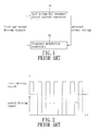
- a half bridge LLC resonant direct current converter 11 is conventionally controlled by a frequency modulation controller 12, which detects an output voltage of the half bridge LLC resonant direct current converter 11 and varies frequency of a switching control signal when the operating condition is varying, so as to maintain the output voltage at the required level.
- the half bridge LLC resonant direct current converter 11 includes two switches (not shown), and the switching control signal includes first and second driving signals (as shown in FIG.2 ).
- the converter 11 since the frequency of the switching control signal varies according to the output voltage, the converter 11 has a range of variation of the switching control signal, making it easy to deviate from an optimal operating point, and in turn resulting in a large design margin in order to overcome uncertainty caused by the variation. Furthermore, the variable frequency characteristic inherent to the half bridge LLC resonant direct current converter 11 also increases the complexity of control.
- the objective of the present invention is to provide a controller that is adapted for use in a resonant direct current/direct current converter so that the resonant direct current/direct current converter operates in an optimal operating frequency, that is, resonant frequency, under different output loading or input conditions.
- a controller adapted for use in a resonant direct current/direct current converter for controlling a switch of the resonant direct current/direct current converter.
- the controller includes a pulse width modulation controlling unit, a fixed frequency signal generating unit, and a logic synthesizing unit.
- the pulse width modulation controlling unit is adapted to be coupled electrically to the resonant direct current/direct current converter for detecting an output voltage of the resonant direct current/direct current converter, and for generating a pulse width modulation signal according to the output voltage detected thereby.
- the fixed frequency signal generating unit is coupled electrically to the pulse-width modulation controlling unit for generating a fixed frequency signal.
- the logic synthesizing unit is coupled electrically to the pulse width modulation controlling unit and the fixed frequency signal generating unit for synthesizing the pulse width modulation signal and the fixed frequency signal so as to generate a driving signal that is adapted to drive the switch of the resonant direct current/direct current converter.
- the preferred embodiment of a controller 3 is adapted for use in a resonant direct current/direct current converter 2.
- the controller 3 is adapted to control a switch of the resonant direct current/direct current converter 2 such that an output voltage (Vo) of the resonant direct current/direct current converter 2 conforms to the requirements.
- the resonant direct current/direct current converter 2 is a symmetrical half bridge LLC resonant direct current/direct current converter, and includes first and second switches 21, 22. Therefore, the controller 3 is adapted to control both the first and second switches 21, 22 of the resonant direct current/direct current converter 2.
- the resonant direct current/direct current converter 2 further includes a capacitor 23, a resonant inductor 24, a transformer 25 and two synchronous rectifiers 26, 27.
- the synchronous rectifiers 26, 27 are coupled electrically to a secondary coil of the transformer 25. Since the resonant direct current/direct current converter 2 is well known in the art, further details of the same are omitted herein for the sake of brevity. It should be noted herein that the controller 3 of the present invention is also applicable for use in other types of resonant direct current/direct current converters, such as asymmetrical LLC, full bridge LLC, symmetrical half bridge LC, asymmetrical LC, and full bridge LC resonant direct current/direct current converters.
- the controller 3 includes a pulse width modulation controlling unit 31, a fixed frequency signal generating unit 32, and a logic synthesizing unit 33.
- the pulse width modulation controlling unit 31 is adapted to be coupled electrically to the resonant direct current/direct current converter 2 for detecting the output voltage (Vo) of the resonant direct current/direct current converter 2, and for generating a pulse width modulation signal according to the output voltage (Vo) detected thereby.
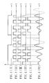
- An exemplary waveform of the pulse width modulation signal is illustrated in FIG.4(I) .
- the fixed frequency signal generating unit 32 is coupled electrically to the pulse-width modulation controlling unit 31 for generating a fixed frequency signal, an exemplary waveform of which is illustrated in FIG.4(II) .
- the fixed frequency signal generating unit 32 receives the pulse width modulation signal from the pulse width modulation controlling unit 31, and uses the pulse width modulation signal as a synchronization signal for generating the fixed frequency signal.
- the fixed frequency signal generating unit 32 uses a rising edge of the pulse width modulation signal as the synchronization signal for generating the fixed frequency signal.
- the logic synthesizing unit 33 is coupled electrically to the pulse width modulation controlling unit 31 and the fixed frequency signal generating unit 32 for synthesizing the pulse width modulation signal and the fixed frequency signal so as to generate a driving signal that is adapted to drive the first and second switches 21, 22 of the resonant direct current/direct current converter 2.
- the fixed frequency signal generated by the fixed frequency signal generating unit 32 is referred to as a first fixed frequency signal.
- the logic synthesizing unit 33 generates a second fixed frequency signal as illustrated in FIG.4(III) from the first fixed frequency signal.
- the second fixed frequency signal has a frequency that is equal to that of the first fixed frequency signal, and a phase that is inverse to that of the first fixed frequency signal.
- the logic synthesizing unit 33 performs multiplication synthesis on the pulse width modulation signal and the first fixed frequency signal so as to generate the driving signal, which is referred to as a first driving signal as illustrated in FIG.4(IV) , for driving the first switch 21 of the resonant direct current/direct current converter 2.
- the logic synthesizing unit 33 further performs multiplication synthesis on the pulse width modulation signal and the second fixed frequency signal so as to generate a second driving signal as illustrated in FIG.4(V) for driving the second switch 22 of the resonant direct current/direct current converter 2.
- the pulse width modulation signal has a duty cycle that varies inversely with a voltage level of the output voltage (Vo) of the resonant direct current/direct current converter 2 detected by the pulse width modulationcontrollingunit 31. It shouldbenotedherein that the pulse width modulation signal has a fixed period. Therefore, when the pulse width modulation controlling unit 31 detects that the voltage level of the output voltage (Vo) of the resonant direct current/direct current converter 2 is too small, the pulse width modulation controlling unit 31 increases the duty cycle of the pulse width modulation signal such that, since the pulse width modulation signal has a fixed period, a time duration of a low signal level of the pulse width modulation signal is accordingly reduced.
- the pulse width modulation controlling unit 31 detects that the voltage level of the output voltage (Vo) of the resonant direct current/direct current converter 2 is too large, the pulse width modulation controlling unit 31 decreases the duty cycle of the pulse width modulation signal such that, since the pulse width modulation signal has a fixed period, the time duration of the low signal level of the pulse width modulation signal is accordingly increased. Consequently, the time duration of the first and second switches 21, 22 being turned on is decreased to thereby decrease the output voltage (Vo) of the resonant direct current/direct current converter 2. As a result, the output voltage (Vo) of the resonant direct current/direct current converter 2 is maintained at a steady level.
- the pulse width modulation controlling unit 31 controls the duty cycle of the pulse width modulation signal merely based on the output voltage (Vo) of the resonant direct current/direct current converter 2. More preferably, the pulse width modulation controlling unit 31 is adapted to further detect a resonant current of the resonant direct current/direct current converter 2, and generates the pulse width modulation signal according to the output voltage (Vo) and the resonant current detected thereby.
- An exemplary waveform of the resonant current is illustrated in FIG.4(VI) . For example, modulation errors between the resonant current and the output voltage (Vo) may be compared to form a double loop control for controlling the duty cycle of the pulse width modulation signal.
- the pulse width modulation signal has a frequency smaller than that of the fixed frequency signal.
- the frequency of the pulse width modulation signal is not greater than one tenth of that of the fixed frequency signal.
- the first and second driving signals are not only adapted for driving the first and second switches 21, 22 of the resonant direct current/direct current converter 2, but may also be adapted for driving the synchronous rectifiers 26, 27.
- the preferred embodiment combines the first and second fixed frequency signals and the pulse width modulation signal for generating the first and second driving signals so as to achieve the control of the resonant direct current/direct current converter 2, operation of the resonant direct current/direct current converter 2 in the optimal operatingpoint (i.e., having a substantially fixed resonating frequency) under all loading conditions can be ensured. Furthermore, by utilizing the first and second driving signals to control the first and second switches 21, 22 of the resonant direct current/direct current converter 2, an optimal design for magnetic components, such as the resonant inductor 24 and the transformer 25, in the resonant direct current/direct current converter 2 can be more easily achieved.
- the rising edge of the pulse width modulation signal is used by the fixed frequency signal generating unit 32 as the synchronization signal for generating the first fixed frequency signal in this embodiment, it can be ensured that a pulse width of a cycle for the first fixed frequency signal is consistently at the high signal level in each duty cycle of the pulse width modulation signal, thereby ensuring a consistent activating state for the resonating current as illustrated in FIG.4(VI) .
- the rising edge of the pulse width modulation signal is used as the synchronization signal for generating the first fixed frequency signal in the preferred embodiment, a falling edge of the pulse width modulation signal may also be used as the synchronization signal for generating the first fixed frequency signal in other embodiments of the present invention.
- the present invention is not limited to this aspect.
- the controller 3 is relatively simple in structure, where control of the switches 21, 22 of the resonant direct current/direct current converter 2 is achieved by using the fixed frequency signal and the pulse width modulation signal, such that the resonant direct current/direct current converter 2 is ensured to operate at the optimal operating point under all loading conditions.
- the controller 3 also reduces the number of switching of the switches 21, 22 of the resonant direct current/direct current converter 2, thereby reducing stress of the switches 21, 22. Consequently, the object of the present invention is achieved.
Landscapes
- Engineering & Computer Science (AREA)
- Power Engineering (AREA)
- Dc-Dc Converters (AREA)
Applications Claiming Priority (1)
| Application Number | Priority Date | Filing Date | Title |
|---|---|---|---|
| TW097103735A TWI346440B (en) | 2008-01-31 | 2008-01-31 | Controller for use in resonant direct current/direct current converter |
Publications (1)
| Publication Number | Publication Date |
|---|---|
| EP2086099A2 true EP2086099A2 (fr) | 2009-08-05 |
Family
ID=40637903
Family Applications (1)
| Application Number | Title | Priority Date | Filing Date |
|---|---|---|---|
| EP08160832A Withdrawn EP2086099A2 (fr) | 2008-01-31 | 2008-07-21 | Contrôleur pour une utilisation dans un convertisseur résonant de courant continu/courant continu |
Country Status (5)
| Country | Link |
|---|---|
| US (1) | US7944715B2 (fr) |
| EP (1) | EP2086099A2 (fr) |
| JP (1) | JP4767294B2 (fr) |
| KR (1) | KR101071291B1 (fr) |
| TW (1) | TWI346440B (fr) |
Families Citing this family (19)
| Publication number | Priority date | Publication date | Assignee | Title |
|---|---|---|---|---|
| TWI392207B (zh) * | 2009-08-05 | 2013-04-01 | Silitek Electronic Guangzhou | 直流/直流轉換裝置與跳頻控制模組及跳頻控制方法 |
| CN102136801B (zh) * | 2010-01-21 | 2014-02-19 | 台达电子工业股份有限公司 | 谐振转换器以及其间歇模式控制方法 |
| WO2013166579A1 (fr) * | 2012-05-10 | 2013-11-14 | Arda Power Inc. | Circuit convertisseur continu-continu utilisant un circuit llc dans une plage de gain de tension supérieure à 1 |
| US9059636B2 (en) | 2010-02-18 | 2015-06-16 | Peter Waldemar Lehn | DC-DC converter circuit using LLC circuit in the region of voltage gain above unity |
| JP2013520148A (ja) | 2010-02-18 | 2013-05-30 | ピーター ヴァルダマー レーン | 高入力対出力電圧変換のためのdc−dcコンバータ回路 |
| CN102281002B (zh) * | 2010-06-09 | 2014-05-14 | 光宝电子(广州)有限公司 | 谐振式电力转换电路 |
| TWI404318B (zh) * | 2010-06-09 | 2013-08-01 | Lite On Electronics Guangzhou | 諧振式電力轉換電路 |
| TWI411204B (zh) * | 2010-09-01 | 2013-10-01 | Lite On Electronics Guangzhou | 諧振變換裝置與諧振變換器的控制模組及其方法 |
| CN102570804B (zh) * | 2010-12-28 | 2015-02-25 | 台达电子工业股份有限公司 | 直流电源转换模组、其控制方法、连接器及能量采集系统 |
| US9379617B2 (en) * | 2012-02-03 | 2016-06-28 | Fuji Electric Co., Ltd. | Resonant DC-DC converter control device |
| US8902089B2 (en) * | 2012-05-02 | 2014-12-02 | Qualcomm Incorporated | Systems and methods for performing digital modulation |
| WO2014012159A1 (fr) * | 2012-07-19 | 2014-01-23 | Frost Damien | Commande multimode d'un convertisseur à résonance en pont complet |
| US9325249B2 (en) | 2013-03-13 | 2016-04-26 | Apple Inc. | Single stage boost-asymmetric LLC |
| JP6341386B2 (ja) * | 2013-05-30 | 2018-06-13 | パナソニックIpマネジメント株式会社 | スイッチング電源装置 |
| CN110504837B (zh) * | 2018-05-16 | 2020-10-30 | 台达电子工业股份有限公司 | 电源转换电路及电源转换电路控制方法 |
| CN109873562B (zh) * | 2019-02-11 | 2020-06-26 | 安徽工业大学 | 一种llc谐振变换器结构及其控制方法 |
| KR102915832B1 (ko) * | 2020-12-10 | 2026-01-22 | 한국전기연구원 | 공진형 컨버터, 그 제어 시스템 및 제어 방법, 및 상기 방법을 실행시키기 위한 컴퓨터 판독 가능한 프로그램을 기록한 기록 매체 |
| CN113098284A (zh) * | 2021-04-15 | 2021-07-09 | 上海奉天电子股份有限公司 | 一种适应宽输出范围变增益llc控制电路 |
| KR102736021B1 (ko) * | 2023-11-09 | 2024-12-03 | 한국철도기술연구원 | Mvdc 배전계통과 연계되는 철도용 컨버터스테이션 및 그 시뮬레이션 방법 |
Family Cites Families (7)
| Publication number | Priority date | Publication date | Assignee | Title |
|---|---|---|---|---|
| JPH0458760A (ja) * | 1990-06-25 | 1992-02-25 | Matsushita Electric Works Ltd | 共振型dc―dcコンバータの出力制御方法 |
| US5687067A (en) * | 1995-05-30 | 1997-11-11 | Philips Electronics North America Corporation | Low noise controller for pulse width modulated converters |
| US6304473B1 (en) * | 2000-06-02 | 2001-10-16 | Iwatt | Operating a power converter at optimal efficiency |
| US6882552B2 (en) * | 2000-06-02 | 2005-04-19 | Iwatt, Inc. | Power converter driven by power pulse and sense pulse |
| DE10322870B4 (de) * | 2003-05-21 | 2009-10-01 | Infineon Technologies Ag | Verfahren zum Betreiben eines Schaltwandlers und Ansteuerschaltung zur Ansteuerung eines Schalters in einem Schaltwandler |
| US7471530B2 (en) * | 2006-10-04 | 2008-12-30 | Power Integrations, Inc. | Method and apparatus to reduce audio frequencies in a switching power supply |
| US20090034298A1 (en) * | 2007-07-30 | 2009-02-05 | Champion Microelectronic Corporation | Control Method And Apparatus Of Resonant Type DC/DC Converter With Low Power Loss At Light Load And Standby |
-
2008
- 2008-01-31 TW TW097103735A patent/TWI346440B/zh not_active IP Right Cessation
- 2008-06-24 US US12/213,708 patent/US7944715B2/en not_active Expired - Fee Related
- 2008-07-16 JP JP2008184632A patent/JP4767294B2/ja not_active Expired - Fee Related
- 2008-07-21 EP EP08160832A patent/EP2086099A2/fr not_active Withdrawn
- 2008-08-29 KR KR1020080084841A patent/KR101071291B1/ko not_active Expired - Fee Related
Also Published As
| Publication number | Publication date |
|---|---|
| TW200934080A (en) | 2009-08-01 |
| JP2009183138A (ja) | 2009-08-13 |
| JP4767294B2 (ja) | 2011-09-07 |
| TWI346440B (en) | 2011-08-01 |
| US20090196080A1 (en) | 2009-08-06 |
| KR20090084637A (ko) | 2009-08-05 |
| KR101071291B1 (ko) | 2011-10-07 |
| US7944715B2 (en) | 2011-05-17 |
Similar Documents
| Publication | Publication Date | Title |
|---|---|---|
| US7944715B2 (en) | Controller for use in a resonant direct current/direct current converter | |
| US8582321B2 (en) | Resonant converters and burst mode control method thereof | |
| US7916506B2 (en) | Control device for use in a resonant direct current/direct current converter | |
| KR100912865B1 (ko) | 스위칭 레귤레이터 및 그 스위칭 레귤레이터를 구비하는반도체 장치 | |
| US9112403B2 (en) | Method for regulating a buck/boost converter | |
| JP2006042598A (ja) | 適応型マルチモードシステム | |
| KR101919625B1 (ko) | 전류제어 모드 dc-dc 컨버터 | |
| WO2008111347A1 (fr) | Régulateur de commutation et son procédé de commande | |
| CN101192797A (zh) | 开关电源电路 | |
| US7764519B2 (en) | Control circuit and method for controlling switching power supply | |
| US7821239B2 (en) | Switching power supply | |
| US8111055B2 (en) | Method for controlling a direct current chopper controller | |
| CN112400273B (zh) | 开关电源 | |
| CN115811207B (zh) | 开关电源控制电路和具有其的开关电源、芯片、设备 | |
| US9559582B2 (en) | Switching power supply circuit | |
| JP4876909B2 (ja) | Dc−dcコンバータおよびその制御方法 | |
| JP2012034516A (ja) | 動作モード切替型dc−dcコンバータ | |
| JP5721403B2 (ja) | 昇降圧回路及び昇降圧回路制御方法 | |
| JP4433841B2 (ja) | スイッチング電源 | |
| JP2012029397A (ja) | 負荷駆動装置 | |
| JP5188939B2 (ja) | 電力変換装置及びその制御方法 | |
| US12009823B2 (en) | Pulse width modulation method | |
| JP2007129853A (ja) | 電源装置 | |
| JP5396878B2 (ja) | クロック同期回路 | |
| JP2005143197A (ja) | Pwm信号の時比率制御方法、時比率制御回路およびdc−dcコンバータ |
Legal Events
| Date | Code | Title | Description |
|---|---|---|---|
| PUAI | Public reference made under article 153(3) epc to a published international application that has entered the european phase |
Free format text: ORIGINAL CODE: 0009012 |
|
| AK | Designated contracting states |
Kind code of ref document: A2 Designated state(s): AT BE BG CH CY CZ DE DK EE ES FI FR GB GR HR HU IE IS IT LI LT LU LV MC MT NL NO PL PT RO SE SI SK TR |
|
| AX | Request for extension of the european patent |
Extension state: AL BA MK RS |
|
| STAA | Information on the status of an ep patent application or granted ep patent |
Free format text: STATUS: THE APPLICATION HAS BEEN PUBLISHED |
|
| STAA | Information on the status of an ep patent application or granted ep patent |
Free format text: STATUS: THE APPLICATION IS DEEMED TO BE WITHDRAWN |
|
| 18D | Application deemed to be withdrawn |
Effective date: 20170201 |