EP2086158A1 - Schéma de récupération d'horloge pour un récepteur optique basé sur la surveillance du précurseur et postcurseur des coefficients de prise - Google Patents
Schéma de récupération d'horloge pour un récepteur optique basé sur la surveillance du précurseur et postcurseur des coefficients de prise Download PDFInfo
- Publication number
- EP2086158A1 EP2086158A1 EP08290079A EP08290079A EP2086158A1 EP 2086158 A1 EP2086158 A1 EP 2086158A1 EP 08290079 A EP08290079 A EP 08290079A EP 08290079 A EP08290079 A EP 08290079A EP 2086158 A1 EP2086158 A1 EP 2086158A1
- Authority
- EP
- European Patent Office
- Prior art keywords
- tap coefficients
- clock
- precursor
- signal
- postcursor
- Prior art date
- Legal status (The legal status is an assumption and is not a legal conclusion. Google has not performed a legal analysis and makes no representation as to the accuracy of the status listed.)
- Granted
Links
Images


Classifications
-
- H—ELECTRICITY
- H04—ELECTRIC COMMUNICATION TECHNIQUE
- H04L—TRANSMISSION OF DIGITAL INFORMATION, e.g. TELEGRAPHIC COMMUNICATION
- H04L7/00—Arrangements for synchronising receiver with transmitter
- H04L7/0054—Detection of the synchronisation error by features other than the received signal transition
- H04L7/0058—Detection of the synchronisation error by features other than the received signal transition detection of error based on equalizer tap values
Definitions
- the invention relates to optical communication systems, in particular to an apparatus and a method for clock recovery for use in a fiber optics receiver.
- high speed data is transmitted without an accompanying clock signal being phase and frequency aligned to the transmitted data.
- the receiver needs to locally generate a clock signal, the phase and frequency thereof being controlled based on the received data, e.g., based on data transitions. This process is called clock recovery.
- a clock recovery circuit uses a phase locked loop (PLL).
- PLL phase locked loop
- an analog phase comparator within the clock recovery circuit compares phase information of the received data signal (in particular the phase information of data transitions), with the phase of a locally generated clock signal, thereby generating a phase error signal characterizing the phase difference.
- the phase error signal is typically low pass filtered (i.e., integrated) before being fed to the input of a voltage controlled oscillator (VCO), with the VCO generating the local clock signal.
- VCO voltage controlled oscillator
- the output frequency of the VCO depends on the input voltage of the VCO.
- the photodetector at the receiver is typically directly fed by on-off modulated light and the resulting current of the photodetector corresponds to the received optical power.
- the phase information is lost (however, with differential detection, phase difference between adjacent bits can be recovered).
- coherent detection receivers the received optical light is coherently superpositioned with a single-frequency optical local oscillator (LO) signal.
- LO optical local oscillator
- Such coherent detection receivers allow detecting the phase of the received signal as necessary for phase modulation schemes (e.g., QPSK - quadrature phase shift keying).
- phase modulation schemes e.g., QPSK - quadrature phase shift keying.
- homodyne detection the carrier frequency of the received optical signal and the frequency of the LO signal coincide.
- the down-converted signal is typically converted to the digital domain by one or more analog-digital-converters and processed in the digital domain.
- Association of coherent detection with digital signal processing allows compensating for high values of chromatic dispersion (CD) and polarization mode dispersion (PMD).
- CD chromatic dispersion
- PMD polarization mode dispersion
- phase information of such highly distorted received signal cannot be determined by an analog phase comparator.
- digital clock recovery schemes may be used which are more tolerant to optical distortion.
- one may use oversampling processing after digital CD compensation.
- existing digital clock recovery schemes in particular digital clock recovery schemes based on oversampling of the received signal, require high processing power and thus suffer from high power dissipation.
- a first aspect of the invention relates to a clock recovery apparatus for use in an optical receiver, in particular for use in a coherent receiver.
- Such receiver comprises electrical sampling means clocked by a clock signal for sampling a received signal, in particular one or more ADCs (analog-digital-converter).
- ADCs analog-digital-converter
- the sampling means may be also realized in form of fully-digital re-sampling means.
- an adaptive multi-tap filter is provided, which is connected downstream of the sampling means and receives adjustable tap coefficients. Besides being used for the clock recovery as will be explained hereinafter, such multi-tap filter is typically provided in an optical receiver with digital signal processing for use of equalization. Also, such filter may be used in a receiver with polarization diversity to combine two received polarization components, in particular to demultiplex a polarization multiplexed signal or a polarization modulated signal.
- Such multi-tap filter comprises one or more tapped delay lines (e.g., four tapped delay lines are typically used for the realization of a polarization demultiplexer).
- a multi-tap delay line has precursor and postcursor taps typically located around a main tap (e.g., the middle tap), with the main coefficient typically having the largest tap coefficient.
- a delay line may have only precursor and post-cursor taps with no distinct main top in between or a plurality of main taps.
- the coefficients determining means may be configured to carry out a constant modulus algorithm (CMA) for determining the tap coefficients.
- CMA constant modulus algorithm
- other algorithms may be used for determining the tap coefficients.
- the inventive clock recovery apparatus is based on using information of tap coefficients and controlling the frequency of a local generated clock in dependency of the information of the tap coefficients.
- the clock recovery apparatus comprises comparison means for comparing precursor and postcursor tap coefficients.
- precursor and postcursor tap coefficients are more or less balanced.
- the coefficients become unbalanced. Such imbalance may be determined by the comparison means and the information is used for controlling the frequency of the clock signal, which is generated in clock generation means.
- the inventive clock recovery apparatus has the advantage of providing a simple and less power consuming scheme for clock recovery based on already available information, i.e., the values of the tap coefficients.
- the clock recovery apparatus is highly distortion tolerant.
- the clock recovery apparatus has only moderate power consumption due to less digital processing effort compared to conventional digital clock recovery schemes.
- precursor and postcursor tap coefficients of a delay line are monitored for clock recovery.
- the same number of precursor and postcursor tap coefficients of a delay line are monitored.
- the comparison means are configured for determining a weight of said precursor tap coefficients and a weight of said post-cursor tap coefficients.
- the comparison means are preferably configured to compare the weight of said precursor tap coefficients with the weight of said postcursor tap coefficients.
- a feedback signal is generated to adjust the frequency of the clock signal.
- the frequency of the clock signal may be increased or decreased as a function of the sign of the imbalance between the weights.
- the comparison means may be configured to generate a signal for increasing the frequency of the clock signal if the weight of said precursor tap coefficients is larger than the weight of said postcursor tap coefficients. If the weight of said postcursor tap coefficients is larger than the weight of said precursor tap coefficients, the comparison means may generate a signal for decreasing the frequency of the clock signal.
- the comparison means may be configured to compare precursor and postcursor tap coefficients associated to a single tapped delay line, e.g. used in feed-forward-equalizer.
- the comparison means are configured to compare precursor and postcursor tap coefficients associated to two or more tapped delay lines (in particular four tapped delay lines), i.e., the comparison means are configured to compare precursor and postcursor tap coefficients associated to two or more FIR (finite impulse response) sub-filters.
- Two or more delay lines may be used in case a plurality of photodetectors is used in the receiver.
- two or more tapped delay lines may be used in a polarization diversity receiver, in a phase diversity receiver or in a receiver having balanced photodiodes.
- Four tapped delay lines may be used to realize a polarization demultiplexer for demultiplexing a polarization multiplexed optical signal as will be explained in more detail later on in the description.
- such polarization demultiplexer may be used to generate two signals assigned to the two orthogonal polarization states.
- a polarization modulated signal optionally also the phase of the optical signal may be modulated, leading to polarization-shift keying in combination with phase-shift keying (e.g. BPSK - binary phase-shift keying).
- phase-shift keying e.g. BPSK - binary phase-shift keying
- four tapped delay lines may be used for realization of a signal equalizer in case of receiving a polarization multiplexed signal or polarization modulated signal (the signal equalizer may be located upstream or downstream of the polarization demultiplexer).
- the filter and the delay lines may be realized in digital hardware (e.g., an ASIC - application-specific integrated circuit; or an FPGA - field-programmable gate array) or in software by using a DSP (digital signal processor).
- digital hardware e.g., an ASIC - application-specific integrated circuit; or an FPGA - field-programmable gate array
- DSP digital signal processor
- a second aspect of the invention relates to an optical receiver, in particular to a coherent receiver, comprising a clock recovery apparatus as discussed above.
- the receiver comprises a polarization demultiplexer or a equalizer realized in form of an adaptive multi-tap filter and precursor and postcursor tap coefficients of the filter are compared to control the frequency of the clock signal.
- a polarization demultiplexer may be used to demultiplex a polarization multiplexed signal.
- a polarization demultiplexer may be used to generate two signals assigned to the two orthogonal polarization states.
- the phase of the optical signal may be modulated.
- a third aspect of the invention relates to a method for clock recovery in such optical receiver.
- the method comprises the step of comparing precursor and postcursor tap coefficients, in particular determining imbalance between the precursor and postcursor tap coefficients.
- the clock signal is controlled in dependency of the comparison.
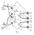
- Fig. 1 shows an embodiment of the optical part of a phase-diversity and polarization-diversity coherent receiver with polarization multiplexing functionality.
- the coherent receiver is configured for receiving and demultiplexing a polarization division multiplexed (PDM) optical signal.
- PDM polarization division multiplexed
- Polarization division multiplexed formats are often used in combination with coherent detection.
- the transmitted PDM signal comprises a first signal component (e.g., a first QPSK signal) having a first polarization and a second signal component (e.g., a second QPSK signal) having a second polarization orthogonal to the first polarization.
- the receiver in Fig. 1 is configured to generate in-phase and quadrature-phase components (phase-diversity) of the downconverted received signal for two orthogonal polarizations (polarization-diversity).
- the receiver comprises a polarization beam splitter (PBS) 1, which splits the received optical signal 2 into a first optical wave and a second optical wave, with the polarizations of the first and second optical waves being orthogonal. Due to shifting of the polarization along the fiber, the signals of the first and second optical waves typically do not correspond to the first and second components of the transmitted PDM signal, respectively.
- PBS polarization beam splitter
- the first optical wave is fed to a first coherent demodulator 3a
- the second optical wave is fed to a second coherent demodulator 3b.
- Both the first coherent demodulator 3a and the second coherent demodulator 3b receive a local oscillator (LO) signal 9 for superimposing the first optical wave and the second optical wave with the LO signal 9, respectively.
- LO local oscillator
- the carrier frequency of the received optical signal 2 and the frequency of the LO signal 9 coincide.
- Polarizers 5 at the inputs of the demodulators 3 a and 3b can be used to improve the polarization quality.
- polarizers 5 at the LO input of both demodulators 3a, 3b a ⁇ /4 wave plate 6a, 6b is provided.
- the wave plates 6a, 6b are used for making the polarization of the LO signal 9 circular, while the signal remains linearly polarized.
- PBS 8a, 8b After passing through half mirrors 7a, 7b for superimposing the LO signal 9 and received signals, PBS 8a, 8b are used for each generating two orthogonal phases.
- the polarization angle of the signal when hitting half mirrors 7a, 7b is 45° with respect to the principal axis of PBS 8a, 8b.
- the four outputs of the two demodulators 3a, 3b are coupled to the inputs of four photodiodes 10a-10d, thereby generating four electrical currents I 10a , I 10b , I 10c , I 10d .
- the beat term of current I 10a of photodiode 10a corresponds to the quadrature-phase component of a first polarization of the downconverted signal.
- the first polarization corresponds to the polarization of the first wave as generated by PBS 1.
- the beat term of current I 10b of photodiode 10b corresponds to the in-phase component of the first polarization of the downconverted signal.
- the beat term of current I 10c of photodiode 10c corresponds to the quadrature-phase component of a second polarization of the downconverted signal.
- the second polarization corresponds to the polarization of the second wave as generated by PBS 1.
- the beat term of current I 10d of photodiode 10d corresponds to the in-phase component of the second polarization of the downconverted signal.
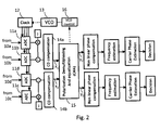
- the downconverted signal components for both polarizations are fed to four ADCs 11a-11d for sampling the signal components.
- the ADCs 11a-11d are clocked by a clock signal supplied by a clock block 12.
- the clock block 12 is configured to supply and (optionally convert) a clock signal as generated by a VCO 13 to the ADCs 11a-11d.
- the clock block 12 may comprise, e.g., one or more clock tree amplifiers, frequency converters (e.g., frequency dividers or multipliers) and/or phase shifters.
- the received digital signals are processed in a digital signal processor (DSP) or in customized digital hardware (or in a combination of both).
- DSP digital signal processor
- the digital output signal of ADC 11a (corresponding to the quadrature-phase component) is multiplied by "j" and added to the digital output signal of ADC 11b (corresponding to the in-phase component).
- the two resulting complex signals are fed in two CD compensation blocks 14a, 14b for compensating CD in the digital domain.
- the two complex output signals x 1 , x 2 of the CD compensation blocks 14a, 14b are fed to a polarization demultiplexing unit and equalization unit 15.
- clock recovery can only be done after compensation of CD (within the DSP). Thus, no standard clock recovery method can be used.
- off-line processing was used having a digital clock recovery block inserted between CD compensation blocks 14a, 14b and polarization demultiplexing and equalization unit 15.
- this approach is only feasible for off-line processing because it involves over-sampling routines that are extremely power-consuming and hence inappropriate for real-time implementation.
- the results from a multi-tap filter used for demultiplexing and/or equalization are used to tune the output frequency of the clock block 12 that clocks the ADCs 11a-11d by the help of a feedback through the VCO 13.
- a feedback signal for clock recovery is extracted from adaptive filter coefficients in the polarization demultiplexer and equalization unit 15.
- the polarization demultiplexing and equalization unit 15 is used to rotate the received signal components x 1 , x 2 for recovering the initial polarization components as multiplexed in the transmitter and for removing interferences between the two polarization components.
- the elements h ij of the rotation matrix represent the coefficients of an adaptive filter, which are temporally updated.
- the coefficients h ij are complex numbers.
- the precursor samples are the samples x 1,2 (k) to x 1,2 (k-N/2+1)
- the postcursor samples are the samples x 1,2 (k-N/2-1) to x 1,2 (k-N).
- the filter as described by the above equation processes at the same time a plurality of samples which are temporally spaced or delayed by one symbol length (T-spaced) or half a symbol length (T/2-spaced).
- the samples used for the filter are called “taps” and the expression "(N+1)-taps filter” means that the filter uses N neighboring taps around a central tap.
- Fig. 3 illustrates an embodiment for such an (N+1)-taps adaptive filter corresponding to the above equation which may be used in the polarization demultiplexing and equalization unit 15.
- the filter and the delay lines may be implemented in digital hardware or in software by using a DSP.
- the filter comprises four FIR sub-filters (finite impulse response).
- Each FIR sub-filter comprises four tapped delay lines, each tapped delay line comprising N identical delay elements 30 having a delay of one symbol length or alternatively a delay of a fraction of a symbol length, e.g., half the symbol length.
- Each delay line has precursor taps and post-cursor taps located around the main tap, with the main tap being the central tap.
- Each tap of the N+1 taps of each delay line is multiplied by a coefficient h ij .
- the multiplied tap values of each tapped delay line are summed in adders 31.
- the first complex signal x 1 associated to a first polarization is fed to the first and second delay lines (numbering of delay lines from top to bottom in Fig. 3 ), whereas the second complex signal x 2 associated to a second polarization is fed to the third and fourth delay lines.
- the outputs of the adders 31 associated to the first and third delay lines are combined by an adder 33, with the output signal y 2 of adder 33 corresponding to the first multiplexed polarization component.
- the outputs of the adders 31 associated to the second and fourth delay lines are combined by an adder 34, with the output signal y 2 of adder 34 corresponding to the second multiplexed polarization component.
- the two adders 31 associated to the first and third delay lines and adder 33 may be combined.
- the two adders 31 associated to second and fourth delay lines and adder 34 may be combined.
- the magnitude of the tap coefficients h ij is decreasing from the main tap (here the central tap) towards the neighboring taps and the main tap should have the highest value.
- the tap coefficients h ij have large values for the central taps and very low values on the neighboring taps.
- the precursor tap coefficients h ij (0) to h ij (N/2-1) are referred to as precursor coefficients and the postcursor tap coefficients h ij ((N/2+1) to h ij (N) are referred to postcursor coefficients.
- the central tap coefficients h ij (N/2) are the main tap coefficients.
- said property of the tap coefficients in the polarization demultiplexing and equalization unit 15 is used to tune the frequency of the clock signal driving the ADCs 11a-11d by means of a feedback (see feedback in Fig. 2 from the polarization demultiplexing block 15 via the VCO control block 16, via the VCO 13, via the clock block 12 to the ADCs 11a-11d).
- the precursor coefficients h ii (0) to h ij (N/2-1) and the postcursor coefficients h ij (N/2+1) to h ij (N) are balanced around the central tap coefficients h ij (N/2).
- the weights of these coefficients become unbalanced.
- the weight w pre of the precursor coefficients may be defined as:
- Fig. 5 illustrates a first embodiment of the polarization demultiplexing and equalization unit 15 in Fig. 2 and an embodiment of the feedback loop for clock recovery.
- the polarization multiplexing and equalization unit 15 comprises four FIR sub-filters for polarization demultiplexing and signal equalization. In Fig. 5 only the tap coefficients of the FIR sub-filters are shown.
- a constant modulus algorithm (CMA) is used, i.e., the tap coefficients h ij of the filter are computed by means of the CMA.
- CMA blocks 40, 41 are provided for performing the CMA and computing the tap coefficients h ij .
- the CMA blocks update the tap coefficients h ij in dependency on the current output values y 1 , y 2 of the polarization multiplexer.
- 2 and ⁇ y 2 1-
- the terms h ij ' denote the updated vectors of tap coefficients h ij (0) to h ij (N)
- the terms h ij denote the actual vectors of tap coefficients h ij (0) to h ij (N)
- ⁇ is a convergence parameter
- the terms x j * denote the actual vector of the complex conjugate of the samples x j (k) to x j (k - N).
- the updated tap coefficients h ij are computed in dependency of the samples x j (k) to x j (k - N) as apparent from the above equations.
- the VCO control block 16 receives the tap coefficients h ij and determines the weight w post of the postcursor coefficients and the weight wpre of the precursor coefficients. If the weight w pre of the precursor coefficients is larger than the weight w post of the postcursor coefficients, a feedback signal is sent to the VCO input to increase the frequency of the recovered clock signal. If the weight w pre of the precursor coefficients is smaller than the weight w post of the postcursor coefficients, a feedback signal is sent to the VCO input to decrease the frequency of the recovered clock signal.
- the VCO control block 16 may also comprise a loop filter, e.g., a low-pass filter. Instead of the VCO control block 16, the CMA blocks may calculate the weights w post and w pre and optionally generate also a comparison signal.
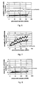
- Fig. 6 shows exemplary time dependent courses of the weight w post of the postcursor coefficients and the weight w precursor of the precursor coefficients computed from an experimental data file.
- the illustrated weights w post and w pre are given in an arbitrary unit.
- a 5-taps T/2-spaced filter is used (in total 4-5 taps).
- the frequency of the clock signal (here: 10.709228 GHz) is set to be matched to the received data signal (the feedback loop in Fig. 5 is not closed).
- Fig. 6 shows that the weights w post and w pre are almost perfectly balanced.
- the bit error ratio (BER) is measured to 1-10 -4 .
- Fig. 7 shows the time dependent courses of the weights w post and w pre when the clock was intentionally shifted by an amount of 100 KHz leading to a clock frequency of 10.709128 GHz (the feedback loop in Fig. 5 is not closed).
- the weights w post and w pre are diverging and most of all not balanced anymore. Due to the frequency shift, the measured BER increases to 2.6 ⁇ 10 -2 .
- the weight w post of the postcursor coefficients is larger than the weight w pre of the precursor coefficients indicating that the frequency of the clock signal has to be increased.
- a feedback signal has to be sent to the clock generation means, i.e., to the VCO 13 to increase the clock frequency.
- Fig. 8 shows the time dependent courses of the weights w post and w pre when the feedback loop is closed and the results from the polarization demultiplexing are fed back.
- the starting clock frequency is set to 10.709128 GHz (i.e., initially the clock frequency has an offset of 100 KHz). Due to the feedback, the frequency of the clock signal is corrected and the clock signal locks to the incoming data signal, thereby the weight w post and w pre tend to converge to the same values resulting to a measured BER of 1.4 ⁇ 10 -4 .
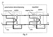
- Fig. 9 illustrates a second embodiment of the polarization demultiplexing and equalization unit 15 in Fig. 2 .
- the unit 15 in Fig. 9 is composed of two parts, a single tap polarization demultiplexer 15a and a multi-tap equalizer 15b.
- Using a separate polarization demultiplexer 15a as shown in Fig. 9 may improve the convergence behavior.
- the polarization demultiplexer 15a performs the rotation function as explained above. In practice, polarization demultiplexing may be not done perfectly by the polarization demultiplexer 15a.
- the equalizer 15b comprises four delay lines associated to four equalizer sub-filters.
- the structure of the equalizer 15b corresponds to the structure of the multi-tap filter in Fig. 3 .
- the tap coefficients of the demultiplexer 15a are determined by using the CMA as explained above (in Fig. 9 the CMA units for computing the coefficients are not shown). Also, the tap coefficients h ij of the equalizer 15b are determined by using the CMA as explained above.
- the equalizer 15b may be connected upstream of the demultiplexer 15a. Further, in both cases the equalizer 15b may have only two delay lines (one delay line per signal path) instead of four delay lines.
Landscapes
- Engineering & Computer Science (AREA)
- Computer Networks & Wireless Communication (AREA)
- Signal Processing (AREA)
- Optical Communication System (AREA)
- Synchronisation In Digital Transmission Systems (AREA)
Priority Applications (2)
| Application Number | Priority Date | Filing Date | Title |
|---|---|---|---|
| AT08290079T ATE514248T1 (de) | 2008-01-29 | 2008-01-29 | Taktrückgewinnungsschema für einen optischen empfänger basierend auf der überwachung der precursor- und postcursor-filterkoeffizienten |
| EP08290079A EP2086158B1 (fr) | 2008-01-29 | 2008-01-29 | Schéma de récupération d'horloge pour un récepteur optique basé sur la surveillance du précurseur et postcurseur des coefficients de prise |
Applications Claiming Priority (1)
| Application Number | Priority Date | Filing Date | Title |
|---|---|---|---|
| EP08290079A EP2086158B1 (fr) | 2008-01-29 | 2008-01-29 | Schéma de récupération d'horloge pour un récepteur optique basé sur la surveillance du précurseur et postcurseur des coefficients de prise |
Publications (2)
| Publication Number | Publication Date |
|---|---|
| EP2086158A1 true EP2086158A1 (fr) | 2009-08-05 |
| EP2086158B1 EP2086158B1 (fr) | 2011-06-22 |
Family
ID=39434013
Family Applications (1)
| Application Number | Title | Priority Date | Filing Date |
|---|---|---|---|
| EP08290079A Active EP2086158B1 (fr) | 2008-01-29 | 2008-01-29 | Schéma de récupération d'horloge pour un récepteur optique basé sur la surveillance du précurseur et postcurseur des coefficients de prise |
Country Status (2)
| Country | Link |
|---|---|
| EP (1) | EP2086158B1 (fr) |
| AT (1) | ATE514248T1 (fr) |
Cited By (3)
| Publication number | Priority date | Publication date | Assignee | Title |
|---|---|---|---|---|
| EP2341642A1 (fr) | 2010-01-05 | 2011-07-06 | Alcatel Lucent | Procédé de transmission de données dans un canal optique |
| US20120121274A1 (en) * | 2009-07-23 | 2012-05-17 | Cisco Technology, Inc. | Clock Recovery for Optical Transmission Systems |
| US20230006867A1 (en) * | 2021-07-01 | 2023-01-05 | Nvidia Corporation | Feed forward filter equalizer adaptation using a constrained filter tap coefficient value |
Citations (5)
| Publication number | Priority date | Publication date | Assignee | Title |
|---|---|---|---|---|
| US4061978A (en) * | 1974-09-11 | 1977-12-06 | Hycom Incorporated | Timing recovery for an automatically equalized data modem |
| US4146840A (en) * | 1978-01-31 | 1979-03-27 | Harris Corporation | Technique for obtaining symbol timing for equalizer weights |
| US4334313A (en) | 1980-09-08 | 1982-06-08 | Bell Telephone Laboratories, Incorporated | Timing recovery technique |
| EP1111837A2 (fr) * | 1999-12-21 | 2001-06-27 | Texas Instruments Incorporated | Procédé et dispositif de récupération d'horloge pour systèmes de télécommunication |
| WO2001091361A1 (fr) * | 2000-05-24 | 2001-11-29 | Infineon Technologies Ag | Procede et dispositif de regulation de cadence d'un recepteur numerique |
-
2008
- 2008-01-29 EP EP08290079A patent/EP2086158B1/fr active Active
- 2008-01-29 AT AT08290079T patent/ATE514248T1/de not_active IP Right Cessation
Patent Citations (5)
| Publication number | Priority date | Publication date | Assignee | Title |
|---|---|---|---|---|
| US4061978A (en) * | 1974-09-11 | 1977-12-06 | Hycom Incorporated | Timing recovery for an automatically equalized data modem |
| US4146840A (en) * | 1978-01-31 | 1979-03-27 | Harris Corporation | Technique for obtaining symbol timing for equalizer weights |
| US4334313A (en) | 1980-09-08 | 1982-06-08 | Bell Telephone Laboratories, Incorporated | Timing recovery technique |
| EP1111837A2 (fr) * | 1999-12-21 | 2001-06-27 | Texas Instruments Incorporated | Procédé et dispositif de récupération d'horloge pour systèmes de télécommunication |
| WO2001091361A1 (fr) * | 2000-05-24 | 2001-11-29 | Infineon Technologies Ag | Procede et dispositif de regulation de cadence d'un recepteur numerique |
Non-Patent Citations (2)
| Title |
|---|
| GITLIN R D ET AL: "CENTER-TAP TRACKING ALGORITHMS FOR TIMING RECOVERY", AT & T TECHNICAL JOURNAL, AMERICAN TELEPHONE AND TELEGRAPH CO. NEW YORK, US, vol. 66, no. 6, 1 November 1987 (1987-11-01), pages 63 - 78, XP000674116, ISSN: 8756-2324 * |
| HODGKISS W: "Equaliser-based clock extraction for modems", ELECTRONICS LETTERS, IEE STEVENAGE, GB, vol. 30, no. 16, 4 August 1994 (1994-08-04), pages 1277 - 1279, XP006000862, ISSN: 0013-5194 * |
Cited By (7)
| Publication number | Priority date | Publication date | Assignee | Title |
|---|---|---|---|---|
| US20120121274A1 (en) * | 2009-07-23 | 2012-05-17 | Cisco Technology, Inc. | Clock Recovery for Optical Transmission Systems |
| US9419726B2 (en) * | 2009-07-23 | 2016-08-16 | Cisco Technology, Inc. | Clock recovery for optical transmission systems |
| US10122470B2 (en) | 2009-07-23 | 2018-11-06 | Cisco Technology, Inc. | Clock recovery for optical transmission systems |
| EP2341642A1 (fr) | 2010-01-05 | 2011-07-06 | Alcatel Lucent | Procédé de transmission de données dans un canal optique |
| WO2011083015A1 (fr) | 2010-01-05 | 2011-07-14 | Alcatel Lucent | Procédé pour transmettre des données sur un canal optique |
| US20230006867A1 (en) * | 2021-07-01 | 2023-01-05 | Nvidia Corporation | Feed forward filter equalizer adaptation using a constrained filter tap coefficient value |
| US11665029B2 (en) * | 2021-07-01 | 2023-05-30 | Nvidia Corporation | Feed forward filter equalizer adaptation using a constrained filter tap coefficient value |
Also Published As
| Publication number | Publication date |
|---|---|
| ATE514248T1 (de) | 2011-07-15 |
| EP2086158B1 (fr) | 2011-06-22 |
Similar Documents
| Publication | Publication Date | Title |
|---|---|---|
| US8655191B2 (en) | Symbol timing recovery in polarization division multiplexed coherent optical transmission system | |
| EP2169867B1 (fr) | Algorithme axé sur la décision pour le réglage d'un démultiplexeur de polarisation dans un récepteur optique cohérent de détection | |
| CN102577183B (zh) | 用于光学传输系统的时钟恢复 | |
| US7769305B1 (en) | High-speed digital signal processing in a coherent optical receiver | |
| US8891980B2 (en) | Digital demodulator architecture | |
| EP3432488B1 (fr) | Dispositif de compensation de caractéristique de transmission, procédé de compensation de caractéristique de transmission et dispositif de communication | |
| EP2498424B1 (fr) | Procédé et système de détection optique cohérente et de traitement du signal | |
| CN101931469B (zh) | 数字相干接收装置 | |
| US9048957B2 (en) | Signal processing circuit, optical receiver, detector and method for compensating for waveform distortion | |
| EP2097997B1 (fr) | Suivi et égalisation de polarisation adaptatifs dans des récepteurs optiques cohérents | |
| JP5850041B2 (ja) | 光受信器、偏波分離装置、および光受信方法 | |
| US7509054B2 (en) | Method for the transmission of optical polarization multiplex signals | |
| CN102511135A (zh) | 路径时延差评估器、路径时延差补偿器和相干接收机 | |
| EP2273700A1 (fr) | Rafales optiques à double polarisation pour la réception d'un récepteur en mode rafale doté d'une adaptation rapide | |
| CN102725982A (zh) | 用于相干偏振复用接收机的时钟恢复方法及时钟恢复设备 | |
| US9608735B2 (en) | MIMO equalization optimized for baud rate clock recovery in coherent DP-QPSK metro systems | |
| US20110033195A1 (en) | Polarization diversity receiver systems and methods with polarization mode dispersion mitigation | |
| CN107852248A (zh) | 光接收器中的信号处理 | |
| JPWO2013128944A1 (ja) | 受信器、伝送システム、偏波多重光信号の受信方法、受信器の制御プログラム | |
| EP2086158B1 (fr) | Schéma de récupération d'horloge pour un récepteur optique basé sur la surveillance du précurseur et postcurseur des coefficients de prise | |
| CN103179060A (zh) | 均衡器的系数更新装置和方法 | |
| EP2251993B1 (fr) | Schéma de réglage pour un démultiplexeur de polarisation dans un récepteur BPSK double polarisation optique | |
| CN102369706B (zh) | 相位偏移和抖动补偿器 |
Legal Events
| Date | Code | Title | Description |
|---|---|---|---|
| PUAI | Public reference made under article 153(3) epc to a published international application that has entered the european phase |
Free format text: ORIGINAL CODE: 0009012 |
|
| AK | Designated contracting states |
Kind code of ref document: A1 Designated state(s): AT BE BG CH CY CZ DE DK EE ES FI FR GB GR HR HU IE IS IT LI LT LU LV MC MT NL NO PL PT RO SE SI SK TR |
|
| AX | Request for extension of the european patent |
Extension state: AL BA MK RS |
|
| 17P | Request for examination filed |
Effective date: 20100205 |
|
| AKX | Designation fees paid |
Designated state(s): AT BE BG CH CY CZ DE DK EE ES FI FR GB GR HR HU IE IS IT LI LT LU LV MC MT NL NO PL PT RO SE SI SK TR |
|
| GRAP | Despatch of communication of intention to grant a patent |
Free format text: ORIGINAL CODE: EPIDOSNIGR1 |
|
| GRAS | Grant fee paid |
Free format text: ORIGINAL CODE: EPIDOSNIGR3 |
|
| GRAA | (expected) grant |
Free format text: ORIGINAL CODE: 0009210 |
|
| AK | Designated contracting states |
Kind code of ref document: B1 Designated state(s): AT BE BG CH CY CZ DE DK EE ES FI FR GB GR HR HU IE IS IT LI LT LU LV MC MT NL NO PL PT RO SE SI SK TR |
|
| REG | Reference to a national code |
Ref country code: GB Ref legal event code: FG4D |
|
| REG | Reference to a national code |
Ref country code: CH Ref legal event code: EP |
|
| REG | Reference to a national code |
Ref country code: IE Ref legal event code: FG4D |
|
| REG | Reference to a national code |
Ref country code: DE Ref legal event code: R096 Ref document number: 602008007769 Country of ref document: DE Effective date: 20110804 |
|
| REG | Reference to a national code |
Ref country code: NL Ref legal event code: VDEP Effective date: 20110622 |
|
| PG25 | Lapsed in a contracting state [announced via postgrant information from national office to epo] |
Ref country code: SE Free format text: LAPSE BECAUSE OF FAILURE TO SUBMIT A TRANSLATION OF THE DESCRIPTION OR TO PAY THE FEE WITHIN THE PRESCRIBED TIME-LIMIT Effective date: 20110622 Ref country code: HR Free format text: LAPSE BECAUSE OF FAILURE TO SUBMIT A TRANSLATION OF THE DESCRIPTION OR TO PAY THE FEE WITHIN THE PRESCRIBED TIME-LIMIT Effective date: 20110622 Ref country code: LT Free format text: LAPSE BECAUSE OF FAILURE TO SUBMIT A TRANSLATION OF THE DESCRIPTION OR TO PAY THE FEE WITHIN THE PRESCRIBED TIME-LIMIT Effective date: 20110622 Ref country code: NO Free format text: LAPSE BECAUSE OF FAILURE TO SUBMIT A TRANSLATION OF THE DESCRIPTION OR TO PAY THE FEE WITHIN THE PRESCRIBED TIME-LIMIT Effective date: 20110922 |
|
| PG25 | Lapsed in a contracting state [announced via postgrant information from national office to epo] |
Ref country code: CY Free format text: LAPSE BECAUSE OF FAILURE TO SUBMIT A TRANSLATION OF THE DESCRIPTION OR TO PAY THE FEE WITHIN THE PRESCRIBED TIME-LIMIT Effective date: 20110622 Ref country code: GR Free format text: LAPSE BECAUSE OF FAILURE TO SUBMIT A TRANSLATION OF THE DESCRIPTION OR TO PAY THE FEE WITHIN THE PRESCRIBED TIME-LIMIT Effective date: 20110923 Ref country code: FI Free format text: LAPSE BECAUSE OF FAILURE TO SUBMIT A TRANSLATION OF THE DESCRIPTION OR TO PAY THE FEE WITHIN THE PRESCRIBED TIME-LIMIT Effective date: 20110622 Ref country code: SI Free format text: LAPSE BECAUSE OF FAILURE TO SUBMIT A TRANSLATION OF THE DESCRIPTION OR TO PAY THE FEE WITHIN THE PRESCRIBED TIME-LIMIT Effective date: 20110622 Ref country code: AT Free format text: LAPSE BECAUSE OF FAILURE TO SUBMIT A TRANSLATION OF THE DESCRIPTION OR TO PAY THE FEE WITHIN THE PRESCRIBED TIME-LIMIT Effective date: 20110622 Ref country code: LV Free format text: LAPSE BECAUSE OF FAILURE TO SUBMIT A TRANSLATION OF THE DESCRIPTION OR TO PAY THE FEE WITHIN THE PRESCRIBED TIME-LIMIT Effective date: 20110622 |
|
| PG25 | Lapsed in a contracting state [announced via postgrant information from national office to epo] |
Ref country code: BE Free format text: LAPSE BECAUSE OF FAILURE TO SUBMIT A TRANSLATION OF THE DESCRIPTION OR TO PAY THE FEE WITHIN THE PRESCRIBED TIME-LIMIT Effective date: 20110622 Ref country code: NL Free format text: LAPSE BECAUSE OF FAILURE TO SUBMIT A TRANSLATION OF THE DESCRIPTION OR TO PAY THE FEE WITHIN THE PRESCRIBED TIME-LIMIT Effective date: 20110622 |
|
| PG25 | Lapsed in a contracting state [announced via postgrant information from national office to epo] |
Ref country code: IS Free format text: LAPSE BECAUSE OF FAILURE TO SUBMIT A TRANSLATION OF THE DESCRIPTION OR TO PAY THE FEE WITHIN THE PRESCRIBED TIME-LIMIT Effective date: 20111022 Ref country code: PT Free format text: LAPSE BECAUSE OF FAILURE TO SUBMIT A TRANSLATION OF THE DESCRIPTION OR TO PAY THE FEE WITHIN THE PRESCRIBED TIME-LIMIT Effective date: 20111024 Ref country code: CZ Free format text: LAPSE BECAUSE OF FAILURE TO SUBMIT A TRANSLATION OF THE DESCRIPTION OR TO PAY THE FEE WITHIN THE PRESCRIBED TIME-LIMIT Effective date: 20110622 Ref country code: EE Free format text: LAPSE BECAUSE OF FAILURE TO SUBMIT A TRANSLATION OF THE DESCRIPTION OR TO PAY THE FEE WITHIN THE PRESCRIBED TIME-LIMIT Effective date: 20110622 |
|
| RAP2 | Party data changed (patent owner data changed or rights of a patent transferred) |
Owner name: ALCATEL LUCENT |
|
| PG25 | Lapsed in a contracting state [announced via postgrant information from national office to epo] |
Ref country code: RO Free format text: LAPSE BECAUSE OF FAILURE TO SUBMIT A TRANSLATION OF THE DESCRIPTION OR TO PAY THE FEE WITHIN THE PRESCRIBED TIME-LIMIT Effective date: 20110622 Ref country code: SK Free format text: LAPSE BECAUSE OF FAILURE TO SUBMIT A TRANSLATION OF THE DESCRIPTION OR TO PAY THE FEE WITHIN THE PRESCRIBED TIME-LIMIT Effective date: 20110622 Ref country code: PL Free format text: LAPSE BECAUSE OF FAILURE TO SUBMIT A TRANSLATION OF THE DESCRIPTION OR TO PAY THE FEE WITHIN THE PRESCRIBED TIME-LIMIT Effective date: 20110622 |
|
| REG | Reference to a national code |
Ref country code: CH Ref legal event code: PCOW Free format text: ALCATEL LUCENT;3, AVENUE OCTAVE GREARD;75007 PARIS (FR) |
|
| PLBE | No opposition filed within time limit |
Free format text: ORIGINAL CODE: 0009261 |
|
| PLAA | Information modified related to event that no opposition was filed |
Free format text: ORIGINAL CODE: 0009299DELT |
|
| PLBE | No opposition filed within time limit |
Free format text: ORIGINAL CODE: 0009261 |
|
| STAA | Information on the status of an ep patent application or granted ep patent |
Free format text: STATUS: NO OPPOSITION FILED WITHIN TIME LIMIT |
|
| 26N | No opposition filed |
Effective date: 20120323 |
|
| PG25 | Lapsed in a contracting state [announced via postgrant information from national office to epo] |
Ref country code: IT Free format text: LAPSE BECAUSE OF FAILURE TO SUBMIT A TRANSLATION OF THE DESCRIPTION OR TO PAY THE FEE WITHIN THE PRESCRIBED TIME-LIMIT Effective date: 20110622 |
|
| R26N | No opposition filed (corrected) |
Effective date: 20120323 |
|
| PG25 | Lapsed in a contracting state [announced via postgrant information from national office to epo] |
Ref country code: DK Free format text: LAPSE BECAUSE OF FAILURE TO SUBMIT A TRANSLATION OF THE DESCRIPTION OR TO PAY THE FEE WITHIN THE PRESCRIBED TIME-LIMIT Effective date: 20110622 |
|
| REG | Reference to a national code |
Ref country code: DE Ref legal event code: R097 Ref document number: 602008007769 Country of ref document: DE Effective date: 20120323 |
|
| PG25 | Lapsed in a contracting state [announced via postgrant information from national office to epo] |
Ref country code: MC Free format text: LAPSE BECAUSE OF NON-PAYMENT OF DUE FEES Effective date: 20120131 |
|
| REG | Reference to a national code |
Ref country code: CH Ref legal event code: PL |
|
| REG | Reference to a national code |
Ref country code: IE Ref legal event code: MM4A |
|
| PG25 | Lapsed in a contracting state [announced via postgrant information from national office to epo] |
Ref country code: CH Free format text: LAPSE BECAUSE OF NON-PAYMENT OF DUE FEES Effective date: 20120131 Ref country code: LI Free format text: LAPSE BECAUSE OF NON-PAYMENT OF DUE FEES Effective date: 20120131 |
|
| PG25 | Lapsed in a contracting state [announced via postgrant information from national office to epo] |
Ref country code: IE Free format text: LAPSE BECAUSE OF NON-PAYMENT OF DUE FEES Effective date: 20120129 |
|
| PG25 | Lapsed in a contracting state [announced via postgrant information from national office to epo] |
Ref country code: ES Free format text: LAPSE BECAUSE OF FAILURE TO SUBMIT A TRANSLATION OF THE DESCRIPTION OR TO PAY THE FEE WITHIN THE PRESCRIBED TIME-LIMIT Effective date: 20111003 |
|
| PG25 | Lapsed in a contracting state [announced via postgrant information from national office to epo] |
Ref country code: BG Free format text: LAPSE BECAUSE OF FAILURE TO SUBMIT A TRANSLATION OF THE DESCRIPTION OR TO PAY THE FEE WITHIN THE PRESCRIBED TIME-LIMIT Effective date: 20110922 |
|
| PG25 | Lapsed in a contracting state [announced via postgrant information from national office to epo] |
Ref country code: MT Free format text: LAPSE BECAUSE OF FAILURE TO SUBMIT A TRANSLATION OF THE DESCRIPTION OR TO PAY THE FEE WITHIN THE PRESCRIBED TIME-LIMIT Effective date: 20110622 |
|
| REG | Reference to a national code |
Ref country code: FR Ref legal event code: GC Effective date: 20131018 |
|
| PG25 | Lapsed in a contracting state [announced via postgrant information from national office to epo] |
Ref country code: TR Free format text: LAPSE BECAUSE OF FAILURE TO SUBMIT A TRANSLATION OF THE DESCRIPTION OR TO PAY THE FEE WITHIN THE PRESCRIBED TIME-LIMIT Effective date: 20110622 |
|
| PG25 | Lapsed in a contracting state [announced via postgrant information from national office to epo] |
Ref country code: LU Free format text: LAPSE BECAUSE OF NON-PAYMENT OF DUE FEES Effective date: 20120129 |
|
| PG25 | Lapsed in a contracting state [announced via postgrant information from national office to epo] |
Ref country code: HU Free format text: LAPSE BECAUSE OF FAILURE TO SUBMIT A TRANSLATION OF THE DESCRIPTION OR TO PAY THE FEE WITHIN THE PRESCRIBED TIME-LIMIT Effective date: 20080129 |
|
| REG | Reference to a national code |
Ref country code: FR Ref legal event code: RG Effective date: 20141016 |
|
| REG | Reference to a national code |
Ref country code: FR Ref legal event code: PLFP Year of fee payment: 8 |
|
| REG | Reference to a national code |
Ref country code: FR Ref legal event code: PLFP Year of fee payment: 9 |
|
| REG | Reference to a national code |
Ref country code: FR Ref legal event code: PLFP Year of fee payment: 10 |
|
| REG | Reference to a national code |
Ref country code: FR Ref legal event code: PLFP Year of fee payment: 11 |
|
| REG | Reference to a national code |
Ref country code: DE Ref legal event code: R082 Ref document number: 602008007769 Country of ref document: DE Representative=s name: METACOM LEGAL RECHTSANWAELTE, DE Ref country code: DE Ref legal event code: R082 Ref document number: 602008007769 Country of ref document: DE Representative=s name: METACOM LEGAL, DE Ref country code: DE Ref legal event code: R081 Ref document number: 602008007769 Country of ref document: DE Owner name: WSOU INVESTMENTS, LLC, LOS ANGELES, US Free format text: FORMER OWNER: ALCATEL LUCENT, PARIS, FR Ref country code: DE Ref legal event code: R082 Ref document number: 602008007769 Country of ref document: DE Representative=s name: BARKHOFF REIMANN VOSSIUS, DE |
|
| REG | Reference to a national code |
Ref country code: GB Ref legal event code: 732E Free format text: REGISTERED BETWEEN 20200820 AND 20200826 |
|
| REG | Reference to a national code |
Ref country code: DE Ref legal event code: R082 Ref document number: 602008007769 Country of ref document: DE Representative=s name: METACOM LEGAL RECHTSANWAELTE, DE Ref country code: DE Ref legal event code: R082 Ref document number: 602008007769 Country of ref document: DE Representative=s name: METACOM LEGAL, DE Ref country code: DE Ref legal event code: R082 Ref document number: 602008007769 Country of ref document: DE Representative=s name: METACOM LEGAL NAGEL MARKOWSKY VOSSIUS RECHTSAN, DE |
|
| P01 | Opt-out of the competence of the unified patent court (upc) registered |
Effective date: 20230606 |
|
| PGFP | Annual fee paid to national office [announced via postgrant information from national office to epo] |
Ref country code: GB Payment date: 20260629 Year of fee payment: 19 |
|
| PGFP | Annual fee paid to national office [announced via postgrant information from national office to epo] |
Ref country code: DE Payment date: 20260629 Year of fee payment: 19 |
|
| PGFP | Annual fee paid to national office [announced via postgrant information from national office to epo] |
Ref country code: FR Payment date: 20260625 Year of fee payment: 19 |