EP2087220B1 - Système évaporateur de carburant pour évaporer des carburants liquides et utilisé dans des dispositifs alimentés par combustion - Google Patents
Système évaporateur de carburant pour évaporer des carburants liquides et utilisé dans des dispositifs alimentés par combustion Download PDFInfo
- Publication number
- EP2087220B1 EP2087220B1 EP20070844832 EP07844832A EP2087220B1 EP 2087220 B1 EP2087220 B1 EP 2087220B1 EP 20070844832 EP20070844832 EP 20070844832 EP 07844832 A EP07844832 A EP 07844832A EP 2087220 B1 EP2087220 B1 EP 2087220B1
- Authority
- EP
- European Patent Office
- Prior art keywords
- liquid fuel
- heated
- evaporator
- evaporator element
- distribution manifold
- Prior art date
- Legal status (The legal status is an assumption and is not a legal conclusion. Google has not performed a legal analysis and makes no representation as to the accuracy of the status listed.)
- Active
Links
Images


Classifications
-
- F—MECHANICAL ENGINEERING; LIGHTING; HEATING; WEAPONS; BLASTING
- F02—COMBUSTION ENGINES; HOT-GAS OR COMBUSTION-PRODUCT ENGINE PLANTS
- F02M—SUPPLYING COMBUSTION ENGINES IN GENERAL WITH COMBUSTIBLE MIXTURES OR CONSTITUENTS THEREOF
- F02M15/00—Carburettors with heating, cooling or thermal insulating means for combustion-air, fuel, or fuel-air mixture
- F02M15/02—Carburettors with heating, cooling or thermal insulating means for combustion-air, fuel, or fuel-air mixture with heating means, e.g. to combat ice-formation
-
- B—PERFORMING OPERATIONS; TRANSPORTING
- B25—HAND TOOLS; PORTABLE POWER-DRIVEN TOOLS; MANIPULATORS
- B25C—HAND-HELD NAILING OR STAPLING TOOLS; MANUALLY OPERATED PORTABLE STAPLING TOOLS
- B25C1/00—Hand-held nailing tools; Nail feeding devices
- B25C1/08—Hand-held nailing tools; Nail feeding devices operated by combustion pressure
-
- F—MECHANICAL ENGINEERING; LIGHTING; HEATING; WEAPONS; BLASTING
- F02—COMBUSTION ENGINES; HOT-GAS OR COMBUSTION-PRODUCT ENGINE PLANTS
- F02M—SUPPLYING COMBUSTION ENGINES IN GENERAL WITH COMBUSTIBLE MIXTURES OR CONSTITUENTS THEREOF
- F02M17/00—Carburettors having pertinent characteristics not provided for in, or of interest apart from, the apparatus of preceding main groups F02M1/00 - F02M15/00
- F02M17/18—Other surface carburettors
- F02M17/26—Other surface carburettors with other wetted bodies
- F02M17/28—Other surface carburettors with other wetted bodies fuel being drawn through a porous body
-
- F—MECHANICAL ENGINEERING; LIGHTING; HEATING; WEAPONS; BLASTING
- F02—COMBUSTION ENGINES; HOT-GAS OR COMBUSTION-PRODUCT ENGINE PLANTS
- F02M—SUPPLYING COMBUSTION ENGINES IN GENERAL WITH COMBUSTIBLE MIXTURES OR CONSTITUENTS THEREOF
- F02M21/00—Apparatus for supplying engines with non-liquid fuels, e.g. gaseous fuels stored in liquid form
- F02M21/02—Apparatus for supplying engines with non-liquid fuels, e.g. gaseous fuels stored in liquid form for gaseous fuels
- F02M21/0203—Apparatus for supplying engines with non-liquid fuels, e.g. gaseous fuels stored in liquid form for gaseous fuels characterised by the type of gaseous fuel
- F02M21/0209—Hydrocarbon fuels, e.g. methane or acetylene
- F02M21/0212—Hydrocarbon fuels, e.g. methane or acetylene comprising at least 3 C-Atoms, e.g. liquefied petroleum gas [LPG], propane or butane
-
- F—MECHANICAL ENGINEERING; LIGHTING; HEATING; WEAPONS; BLASTING
- F02—COMBUSTION ENGINES; HOT-GAS OR COMBUSTION-PRODUCT ENGINE PLANTS
- F02M—SUPPLYING COMBUSTION ENGINES IN GENERAL WITH COMBUSTIBLE MIXTURES OR CONSTITUENTS THEREOF
- F02M21/00—Apparatus for supplying engines with non-liquid fuels, e.g. gaseous fuels stored in liquid form
- F02M21/02—Apparatus for supplying engines with non-liquid fuels, e.g. gaseous fuels stored in liquid form for gaseous fuels
- F02M21/0218—Details on the gaseous fuel supply system, e.g. tanks, valves, pipes, pumps, rails, injectors or mixers
- F02M21/0248—Injectors
- F02M21/0281—Adapters, sockets or the like to mount injection valves onto engines; Fuel guiding passages between injectors and the air intake system or the combustion chamber
-
- F—MECHANICAL ENGINEERING; LIGHTING; HEATING; WEAPONS; BLASTING
- F02—COMBUSTION ENGINES; HOT-GAS OR COMBUSTION-PRODUCT ENGINE PLANTS
- F02M—SUPPLYING COMBUSTION ENGINES IN GENERAL WITH COMBUSTIBLE MIXTURES OR CONSTITUENTS THEREOF
- F02M21/00—Apparatus for supplying engines with non-liquid fuels, e.g. gaseous fuels stored in liquid form
- F02M21/02—Apparatus for supplying engines with non-liquid fuels, e.g. gaseous fuels stored in liquid form for gaseous fuels
- F02M21/06—Apparatus for de-liquefying, e.g. by heating
-
- F—MECHANICAL ENGINEERING; LIGHTING; HEATING; WEAPONS; BLASTING
- F23—COMBUSTION APPARATUS; COMBUSTION PROCESSES
- F23D—BURNERS
- F23D11/00—Burners using a direct spraying action of liquid droplets or vaporised liquid into the combustion space
- F23D11/36—Details
- F23D11/44—Preheating devices; Vaporising devices
- F23D11/441—Vaporising devices incorporated with burners
- F23D11/443—Vaporising devices incorporated with burners heated by the main burner flame
- F23D11/445—Vaporising devices incorporated with burners heated by the main burner flame the flame and the vaporiser not coming into direct contact
-
- F—MECHANICAL ENGINEERING; LIGHTING; HEATING; WEAPONS; BLASTING
- F23—COMBUSTION APPARATUS; COMBUSTION PROCESSES
- F23D—BURNERS
- F23D14/00—Burners for combustion of a gas, e.g. of a gas stored under pressure as a liquid
- F23D14/28—Burners for combustion of a gas, e.g. of a gas stored under pressure as a liquid in association with a gaseous fuel source, e.g. acetylene generator, or a container for liquefied gas
-
- F—MECHANICAL ENGINEERING; LIGHTING; HEATING; WEAPONS; BLASTING
- F02—COMBUSTION ENGINES; HOT-GAS OR COMBUSTION-PRODUCT ENGINE PLANTS
- F02B—INTERNAL-COMBUSTION PISTON ENGINES; COMBUSTION ENGINES IN GENERAL
- F02B63/00—Adaptations of engines for driving pumps, hand-held tools or electric generators; Portable combinations of engines with engine-driven devices
- F02B63/02—Adaptations of engines for driving pumps, hand-held tools or electric generators; Portable combinations of engines with engine-driven devices for hand-held tools
-
- F—MECHANICAL ENGINEERING; LIGHTING; HEATING; WEAPONS; BLASTING
- F02—COMBUSTION ENGINES; HOT-GAS OR COMBUSTION-PRODUCT ENGINE PLANTS
- F02M—SUPPLYING COMBUSTION ENGINES IN GENERAL WITH COMBUSTIBLE MIXTURES OR CONSTITUENTS THEREOF
- F02M21/00—Apparatus for supplying engines with non-liquid fuels, e.g. gaseous fuels stored in liquid form
- F02M21/02—Apparatus for supplying engines with non-liquid fuels, e.g. gaseous fuels stored in liquid form for gaseous fuels
- F02M21/0218—Details on the gaseous fuel supply system, e.g. tanks, valves, pipes, pumps, rails, injectors or mixers
- F02M21/023—Valves; Pressure or flow regulators in the fuel supply or return system
- F02M21/0236—Multi-way valves; Multiple valves forming a multi-way valve system
-
- F—MECHANICAL ENGINEERING; LIGHTING; HEATING; WEAPONS; BLASTING
- F02—COMBUSTION ENGINES; HOT-GAS OR COMBUSTION-PRODUCT ENGINE PLANTS
- F02M—SUPPLYING COMBUSTION ENGINES IN GENERAL WITH COMBUSTIBLE MIXTURES OR CONSTITUENTS THEREOF
- F02M21/00—Apparatus for supplying engines with non-liquid fuels, e.g. gaseous fuels stored in liquid form
- F02M21/02—Apparatus for supplying engines with non-liquid fuels, e.g. gaseous fuels stored in liquid form for gaseous fuels
- F02M21/0218—Details on the gaseous fuel supply system, e.g. tanks, valves, pipes, pumps, rails, injectors or mixers
- F02M21/023—Valves; Pressure or flow regulators in the fuel supply or return system
- F02M21/0239—Pressure or flow regulators therefor
-
- Y—GENERAL TAGGING OF NEW TECHNOLOGICAL DEVELOPMENTS; GENERAL TAGGING OF CROSS-SECTIONAL TECHNOLOGIES SPANNING OVER SEVERAL SECTIONS OF THE IPC; TECHNICAL SUBJECTS COVERED BY FORMER USPC CROSS-REFERENCE ART COLLECTIONS [XRACs] AND DIGESTS
- Y02—TECHNOLOGIES OR APPLICATIONS FOR MITIGATION OR ADAPTATION AGAINST CLIMATE CHANGE
- Y02T—CLIMATE CHANGE MITIGATION TECHNOLOGIES RELATED TO TRANSPORTATION
- Y02T10/00—Road transport of goods or passengers
- Y02T10/10—Internal combustion engine [ICE] based vehicles
- Y02T10/30—Use of alternative fuels, e.g. biofuels
-
- Y—GENERAL TAGGING OF NEW TECHNOLOGICAL DEVELOPMENTS; GENERAL TAGGING OF CROSS-SECTIONAL TECHNOLOGIES SPANNING OVER SEVERAL SECTIONS OF THE IPC; TECHNICAL SUBJECTS COVERED BY FORMER USPC CROSS-REFERENCE ART COLLECTIONS [XRACs] AND DIGESTS
- Y10—TECHNICAL SUBJECTS COVERED BY FORMER USPC
- Y10T—TECHNICAL SUBJECTS COVERED BY FORMER US CLASSIFICATION
- Y10T137/00—Fluid handling
- Y10T137/6416—With heating or cooling of the system
Definitions
- the present invention relates generally to combustion-powered systems, and more particularly to new and improved liquid fuel supply and evaporator system for use in connection with combustion-powered devices, such as, for example, combustion-powered tools, more specifically, combustion-powered fastener-driving tools, wherein the new and improved evaporator system can be utilized to effectively convert a liquid fuel into a gaseous fuel for combustion within the combustion chamber of a combustion-powered fastener-driving tool such that liquid fuel sources, as well as gaseous fuel sources, can be utilized to power combustion-powered fastener-driving tools.
- combustion-powered devices such as, for example, combustion-powered tools, more specifically, combustion-powered fastener-driving tools
- the new and improved evaporator system can be utilized to effectively convert a liquid fuel into a gaseous fuel for combustion within the combustion chamber of a combustion-powered fastener-driving tool such that liquid fuel sources, as well as gaseous fuel sources, can be utilized to power combustion-powered fastener-driving tools
- Portable combustion-powered tools having various different means for conducting or charging a combustible fuel into a suitable combustion chamber, are of course well-known. Examples of such portable power tools are disclosed within United States Patent 6,912,988 which issued to Adams on July 5, 2005 , United States Patent 4,905,634 which issued to Veldman on March 6, 1990 and United States Patent 4,821,683 which issued to Veldman on April 18, 1989 .
- the portable combustion-powered tools can utilize any one of various gaseous fuels, such as, for example, compressed natural gas, liquid petroleum gas, butane, or the like.
- the introduction of the incoming gaseous fuel is also utilized to effectively induce or entrain the flow of ambient air into the combustion chamber of the power tool either for scavenging purposes in connection with residual gases that will be present within the combustion chamber upon completion of a particular power tool firing cycle, or for charging purposes in connection with the preparation for and initiation of a subsequent power tool firing cycle.
- the portable combustion-powered tools as disclosed within the aforenoted patents, are generally satisfactory, it is noted that such portable power tools nevertheless exhibit some operational drawbacks or limitations, particularly when it is desired to utilize liquid fuels as the fuel source.
- liquid fuels firstly be converted into gaseous fuels so as to enable the fuels to undergo properly controlled combustion.
- a predetermined amount of the liquid fuel be supplied so as to achieve proper or more accurate stoichiometric air-fuel ratios.
- a liquid fuel supply and evaporator system for converting a liquid fuel into a gaseous fuel, comprising: a liquid fuel supply source; an evaporator element for converting a liquid fuel into a gaseous fuel by an evaporation process; a liquid fuel distribution manifold interposed between said liquid fuel supply source and said evaporator element for conducting a liquid fuel from said liquid fuel supply source into said evaporator element; and a heated housing disposed in thermal communication with said evaporator element so as to heat said evaporator element whereby said heated evaporator element can convert the liquid fuel into a gaseous fuel by means of the evaporation process.
- a sintered metal liquid fuel evaporator element is disposed internally within the evaporator housing so as to be heated thereby, and a liquid fuel distribution manifold is disposed internally within the sintered metal liquid fuel evaporator element so as to charge liquid fuel, supplied to the liquid fuel distribution manifold from a liquid fuel source, into the sintered metal liquid fuel evaporator element.
- a liquid fuel portioning valve is interposed between the liquid fuel source and the liquid fuel distribution manifold so as to discharge a predetermined amount of the liquid fuel into the liquid fuel distribution manifold.
- the liquid fuel, charged into and dispersed within the sintered metal liquid fuel evaporator element, is effectively converted from a liquid fuel into a gaseous fuel which is then transmitted by means of a gas distribution manifold, incorporated within the evaporator housing, toward the combustion chamber of the portable combustion powered fastener-driving tool.
- the new and improved fuel evaporator system comprises a gaseous fuel discharge port which is defined within said heated housing ; and said evaporator element has a substantially conical configuration such that a downstream end portion of said evaporator element is disposed in fluidic communication with said gaseous fuel discharge port so as to fluidically conduct the gaseous fuel into said gaseous fuel discharge port.
- the invention also relates to a method of converting a liquid fuel into a gaseous fuel according to claim 7.
- FIGURES 1 and 2 a new and improved liquid fuel supply and evaporator system, which has been constructed in accordance with the principles and teachings of the present invention for effectively vaporizing liquid fuels such that liquid fuel sources can be used within portable combustion-powered devices, such as, for example, portable combustion-powered fastener-driving tools, and which discloses the various structural components thereof prior to the initiation of a fuel-injection operative cycle, is disclosed and is generally indicated by the reference character 100.
- the new and improved liquid fuel supply and evaporator system 100 comprises an evaporator housing 102 which is fabricated from a suitable metal or other heat conducting material so as to be capable of absorbing heat in order to, in turn, provide the necessary heat for vaporizing a liquid fuel as will be more fully appreciated hereinafter.
- the evaporator housing 102 is adapted to be disposed in thermal communication with, for example, the combustion chamber housing of the portable combustion-powered fastener-driving tool so as to in fact absorb the heat or thermal energy generated within, and emitted by, the combustion chamber housing of the combustion-powered fastener-driving tool as a result of the combustion process which cyclically occurs within the combustion chamber.
- the axially central portion of the evaporator housing 102 is provided with a substantially frusto-conically-shaped axially extending bore 104, and that a substantially correspondingly frusto-conically configured sintered metal liquid fuel evaporator element 106 is adapted to be disposed within the bore 104 such that the external peripheral wall surface portion 108 of the sintered metal liquid fuel evaporator element 106 is disposed in surface-to-surface contact with the internal peripheral wall surface portion 110 of the evaporator housing 102 which defines bore 104.
- the axially central portion of the sintered metal liquid fuel evaporator element 106 is likewise provided with a substantially conically-shaped axially extending bore 112, and that a substantially correspondingly configured liquid fuel distribution manifold 114, which is also preferably fabricated from a suitable metal, is adapted to be disposed within the bore 112 such that the external peripheral wall surface portion 116 of the liquid fuel distribution manifold 114 is disposed in surface-to-surface contact with the internal peripheral wall surface portion 118 of the sintered metal liquid fuel evaporator element 106 which defines bore 112.
- the upstream or rear end portion of the liquid fuel distribution manifold 114 is counterbored, as at 120, so as to receive a liquid fuel inlet fitting and actuator 122 which is operatively attached to a liquid fuel portioning valve 124 as can best be seen in FIGURE 1 , whereby the counterbored region 120 of the liquid fuel distribution manifold 114 also effectively defines or serves as a liquid fuel inlet port 126.
- the liquid fuel portioning valve 124 is, in turn, operatively connected to, for example, a liquid petroleum gas fuel source 128 by means of a fluid conduit 129, and in this manner, when the liquid fuel inlet fitting and actuator 122 is in fact actuated, a predetermined amount of the liquid fuel, as supplied from the liquid petroleum gas fuel source 128, is dispensed or injected from the liquid fuel inlet fitting and actuator 122 into the liquid fuel inlet port 126 of the counterbored liquid fuel distribution manifold 114.
- the liquid fuel distribution manifold 114 has an axial passageway or bore 130 defined therein which is coaxially disposed with respect to the liquid fuel inlet fitting and actuator 122 and which extends axially from the axial central portion of the liquid fuel distribution manifold 114 toward the pointed forward or downstream end portion of the liquid fuel distribution manifold 114, and a pair of axially spaced transversely oriented passageways or bores 132,134 which are fluidically connected to the axially oriented passageway or bore 130.
- liquid fuel inlet fitting and actuator 122 when the liquid fuel inlet fitting and actuator 122 is in fact actuated, a predetermined amount of the liquid fuel, as supplied from the liquid petroleum gas fuel source 128, is dispensed from the liquid fuel inlet fitting and actuator 122 into the liquid fuel inlet port 126 of the counterbored liquid fuel distribution manifold 114, the liquid fuel will be further conducted into the axially oriented passageway or bore 130, and will, in turn, be conducted, through means of the transversely oriented passageways or bores 132,134, into the sintered metal liquid fuel evaporator element 106.
- the liquid fuel effectively injected or charged into the sintered metal liquid fuel evaporator element 106, will be dispersed within and throughout the sintered metal liquid fuel evaporator element 106 in preparation for being converted from its liquid state into a gaseous state as a result of being evaporated when heat or thermal radiation is transmitted or conducted from the evaporator housing 102 to the sintered metal liquid fuel evaporator element 106.
- the forward or downstream end portion of the evaporator housing 102 which defines the substantially frusto-conically-shaped axially extending bore 104, is also counterbored so as to effectively form or define an annular shoulder portion 136, and correspondingly, the downstream or forward end portion of the frusto-conically configured sintered metal liquid fuel evaporator element 106 has a planar surface portion 138 which is adapted to be seated upon the annular shoulder portion 136 of the evaporator housing 102 when the sintered metal liquid fuel evaporator element 106 is installed within the evaporator housing 102 as illustrated within FIGURE 1 .
- the annular shoulder portion 136 of the evaporator housing 102 annularly surrounds an axially located gaseous fuel discharge port 140, and it can therefore be appreciated that, as a result of the frusto-conically configured sintered metal liquid fuel evaporator element 106, once the liquid fuel, dispersed within and throughout the sintered metal liquid fuel evaporator element 106, has effectively been converted from its liquid state to its gaseous state, the flow of the gaseous fuel will in effect be naturally fluidically conducted toward the gaseous fuel discharge port 140.
- gaseous fuel discharge port 140 is fluidically connected to a central portion of a transversely oriented passageway 142 which is formed within the forward or downstream end portion of the evaporator housing 102 and which effectively defines or forms a gaseous fuel distribution manifold.
- Opposite end portions of the gaseous fuel distribution manifold 142 are respectively provided with an exhaust port 144,146, and a pair of gaseous fuel discharge nozzles 148,150 are fixedly mounted within the exhaust ports 144,146 so as to discharge the gaseous fuel toward the combustion chamber 152 of, for example, a combustion-powered fastener-driving tool.
- the rear or upstream end portion of the evaporator housing 102 is also provided with a counterbored region 154 so as to effectively define an annular shoulder portion 156 upon the evaporator housing 102. It is also seen that the upstream or rear end portion of the liquid fuel distribution manifold 114 is provided with an annular flanged portion 158.
- the flanged portion 158 of the liquid fuel distribution manifold 114 will be seated within the counter-bored region 154 of the evaporator housing 102 and will be engaged with the annular shoulder portion 156 of the evaporator housing 102.
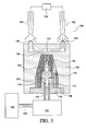
- liquid fuel portioning valve 124 when the liquid fuel portioning valve 124 is pushed or moved upwardly from its normal, non-actuated position, as illustrated within FIGURE 1 , to its actuated position as illustrated within FIGURE 3 , a predetermined amount of liquid fuel, as supplied from the liquid fuel source 128 and through the liquid fuel conduit 129, is dispensed or injected by means of the liquid fuel portioning valve 124 through the liquid fuel inlet port 126 and into the axially oriented passageway or bore 130 defined within the liquid fuel distribution manifold 114.
- the liquid fuel will, in turn, flow through the axially oriented passageway or bore 130, as well as into and through the transversely oriented passageways or bores 132,134 whereby the liquid fuel will be dispersed into oppositely disposed side portions of the sintered metal liquid fuel evaporator element 106.
- the evaporator housing 102 is disposed in thermal communication with a heat source of the combustion-powered tool, such as, for example, the combustion chamber housing of the combustion-powered tool, and since the evaporator housing 102 is fabricated from a suitable heat conductive material, such as, for example, a suitable metal, the evaporator housing 102 will be heated by means of the heat or thermal radiation generated within the tool combustion chamber 152 and emitted by the tool combustion chamber housing.
- liquid fuel distribution manifold 114 is likewise disposed in thermal communication with the evaporator housing 102 as a result of the flanged portion 158 of the liquid fuel distribution manifold 114 being disposed within the counter-bored region 154 of the evaporator housing 102 wherein the flanged portion 158 of the liquid fuel distribution manifold 114 is disposed in contact with the shoulder portion 156 of the evaporator housing 102.
- the liquid fuel distribution manifold 114 will be indirectly heated by means of the heat or thermal radiation generated within the tool combustion chamber 152 and emitted by the tool combustion chamber housing, that is, through means of the evaporator housing 102, and accordingly still further, it can be appreciated that both the internal and external regions of the sintered metal liquid fuel evaporator element 106 will be respectively heated by means of the liquid fuel distribution manifold 114 and the evaporator housing 102.
- the gaseous fuel will be discharged from the sintered metal liquid fuel evaporator element 106 through means of the front or downstream planar surface portion 138 and the gaseous fuel discharge port 140 so as to flow into the gaseous fuel distribution manifold 142. From the gaseous fuel distribution manifold 142, the gaseous fuel can then flow through the pair of gaseous fuel discharge nozzles 148,150 and into the combustion chamber 152.
- gaseous fuel can be conducted from the pair of gaseous fuel discharge nozzles 148,150 directly into the combustion chamber 152 as illustrated, for example, within FIGURE 2
- the gaseous fuel can alternatively be conducted from the pair of gaseous fuel discharge nozzles 148,150 through a pair of jet pump venturi structures 160,162 wherein ambient air is effectively entrained into the jet pump venturi structures 160,162, as the gaseous fuel flows through the jet pump venturi structures, so as to form air/fuel mixtures to be conducted into the combustion chamber 152, all as illustrated within FIGURE 3 .
- a new and improved liquid fuel supply and evaporator system for use in connection with combustion-powered devices, such as, for example, combustion-powered tools, more specifically, combustion-powered fastener-driving tools
- the new and improved fuel evaporator system comprises an evaporator housing which is adapted to be disposed in thermal communication with, for example, the combustion chamber housing of the portable combustion-powered fastener-driving tool in order to absorb the heat or thermal radiation generated within, and emitted by, the combustion chamber housing as a result of the combustion process which cyclically occurs within the combustion chamber.
- a sintered metal liquid fuel evaporator element is disposed internally within the evaporator housing so as to be heated thereby, and a liquid fuel distribution manifold is disposed internally within the sintered metal liquid fuel evaporator element so as to charge liquid fuel, supplied to the liquid fuel distribution manifold from a liquid fuel source, into the sintered metal liquid fuel evaporator element.
- a liquid fuel portioning valve is interposed between the liquid fuel source and the liquid fuel distribution manifold so as to discharge a pre-determined amount of the liquid fuel into the liquid fuel distribution manifold.
- the liquid fuel, charged into and dispersed within the sintered metal liquid fuel evaporator element, is effectively converted from a liquid fuel into a gaseous fuel which is then transmitted by means of a gas distribution manifold, incorporated within the evaporator housing, toward the combustion chamber of the portable combustion powered fastener-driving tool.
- the portable combustion-powered fastener-driving tool is therefore capable of being operated with liquid fuels as opposed to being required to be operated only with gaseous fuels.
Landscapes
- Engineering & Computer Science (AREA)
- Chemical & Material Sciences (AREA)
- Combustion & Propulsion (AREA)
- Mechanical Engineering (AREA)
- General Engineering & Computer Science (AREA)
- Chemical Kinetics & Catalysis (AREA)
- General Chemical & Material Sciences (AREA)
- Oil, Petroleum & Natural Gas (AREA)
- Spray-Type Burners (AREA)
- Feeding And Controlling Fuel (AREA)
- Wick-Type Burners And Burners With Porous Materials (AREA)
- Portable Nailing Machines And Staplers (AREA)
Claims (7)
- Système d'alimentation et d'évaporation de combustible liquide (100) pour convertir un combustible liquide en combustible gazeux, comprenant :une source d'alimentation en combustible liquide (128) ;un élément évaporateur (106) pour convertir un combustible liquide en combustible gazeux par un processus d'évaporation ;un collecteur de distribution de combustible liquide (114) interposé entre ladite source d'alimentation en combustible liquide et ledit élément évaporateur pour conduire un combustible liquide depuis ladite source d'alimentation en combustible liquide dans ledit élément évaporateurun boîtier chauffé (102) disposé en communication thermique avec ledit élément évaporateur de manière à chauffer ledit élément évaporateur, ce par quoi ledit élément évaporateur chauffé peut convertir le combustible liquide en un combustible gazeux au moyen du processus d'évaporation ;un orifice de décharge de combustible gazeux (140) défini dans ledit boîtier chauffé ;et ledit collecteur de distribution de combustible liquide (114) étant disposé en communication thermique avec ledit boîtier chauffé (102) de manière à être chauffé par ledit boîtier chauffé ;et ledit élément évaporateur (106) :- étant interposé entre ledit boîtier chauffé (102) et ledit collecteur de distribution de combustible liquide chauffé (114) de manière à être chauffé à la fois par ledit boîtier chauffé et par ledit collecteur de distribution de combustible liquide chauffé ; et- étant disposé à l'intérieur dans ledit boîtier chauffé de telle sorte que des portions de paroi externe (108) dudit élément évaporateur soient disposées en contact avec des portions de paroi interne (110) dudit boîtier chauffé (102) ; etledit collecteur de distribution de combustible liquide chauffé (114) étant disposé à l'intérieur dans ledit élément évaporateur (106) de telle sorte que des portions de paroi externe (116) dudit collecteur de distribution de combustible liquide chauffé soient disposées en contact avec des portions de paroi interne (118) dudit élément évaporateur,caractérisé en ce que ledit élément évaporateur (106) a une configuration au moins substantiellement conique de telle sorte qu'une portion d'extrémité aval dudit élément évaporateur soit disposée en communication fluidique avec ledit orifice de décharge de combustible gazeux (140) de manière à conduire fluidiquement le combustible gazeux dans ledit orifice de décharge de combustible gazeux.
- Système d'alimentation et d'évaporation de combustible liquide selon la revendication 1, dans lequel :ledit élément évaporateur (106) est fabriqué à partir de métal fritté.
- Système d'alimentation et d'évaporation de combustible liquide selon la revendication 1, comprenant en outre :une soupape de séparation de liquide (124) interposée entre ladite source d'alimentation en combustible liquide et ledit collecteur de distribution de combustible liquide pour distribuer une quantité prédéterminée de combustible liquide depuis ladite source d'alimentation en combustible liquide dans ledit collecteur de distribution de combustible liquide.
- Système d'alimentation et d'évaporation de combustible liquide selon la revendication 1, dans lequel :ledit collecteur de distribution de combustible liquide (114) a une pluralité de passages de fluide (132, 134) définis à l'intérieur de celui-ci pour distribuer le combustible liquide,distribué dans ceux-ci par ladite soupape de séparation de liquide, vers différentes régions dudit élément évaporateur.
- Système d'alimentation et d'évaporation de combustible liquide selon la revendication 1, dans lequel :ledit collecteur de distribution de combustible liquide (114) est fabriqué en métal.
- Système d'alimentation et d'évaporation de combustible liquide selon la revendication 1, comprenant en outre :une pluralité de buses de décharge de combustible gazeux (148, 150) disposées sur ledit boîtier chauffé pour décharger du combustible gazeux vers l'appareil de combustion dans lequel le combustible gazeux doit être brûle ; etun collecteur de distribution de combustible gazeux (142) défini dans ledit boîtier chauffé et reliant fluidiquement ledit orifice de décharge de combustible gazeux et ladite pluralité de buses de décharge de combustible gazeux de manière à distribuer le combustible gazeux depuis ledit orifice de décharge de combustible gazeux (140) jusqu'à ladite pluralité de buses de décharge de combustible gazeux (148, 150).
- Procédé pour convertir un combustible liquide en un combustible gazeux, comprenant les étapes consistant à :fournir un combustible liquide à partir d'une source d'alimentation en combustible liquide ;fournir un élément évaporateur (106) pour convertir le combustible liquide en un combustible gazeux par un processus d'évaporation ;interposer un collecteur de distribution de combustible liquide (114) entre ladite source d'alimentation en combustible liquide et ledit élément évaporateur de manière à conduire le combustible liquide depuis ladite source d'alimentation en combustible liquide jusque dans ledit élément évaporateur ;disposer un boîtier chauffé (102) en communication thermique avec ledit élément évaporateur (106) de manière à chauffer ledit élément évaporateur ce par quoi ledit élément évaporateur chauffé peut convertir le combustible liquide en combustible gazeux au moyen du processus d'évaporation ; etfournir un orifice de décharge de combustible gazeux (140) défini dans ledit boîtier chauffé ;et ledit collecteur de distribution de combustible liquide (114) étant disposé en communication thermique avec ledit boîtier chauffé (102) de manière à être chauffé par ledit boîtier chauffé ;et ledit élément évaporateur (106) :- étant interposé entre ledit boîtier chauffé (102) et ledit collecteur de distribution de combustible liquide chauffé (114) de manière à être chauffé à la fois par ledit boîtier chauffé et par ledit collecteur de distribution de combustible liquide chauffé ; et- étant disposé à l'intérieur dans ledit boîtier chauffé de telle sorte que des portions de paroi externe (108) dudit élément évaporateur soient disposées en contact avec des portions de paroi interne (110) dudit boîtier chauffé (102) ;
etledit collecteur de distribution de combustible liquide chauffé (114) étant disposé à l'intérieur dans ledit élément évaporateur (106) de telle sorte que des portions de paroi externe (116) dudit collecteur de distribution de combustible liquide chauffé soient disposées en contact avec des portions de paroi interne (118) dudit élément évaporateur,caractérisé en ce que ledit élément évaporateur (106) a une configuration au moins substantiellement conique de telle sorte qu'une portion d'extrémité aval dudit élément évaporateur soit disposée en communication fluidique avec ledit orifice de décharge de combustible gazeux (140) de manière à conduire fluidiquement le combustible gazeux dans ledit orifice de décharge de combustible gazeux.
Applications Claiming Priority (3)
| Application Number | Priority Date | Filing Date | Title |
|---|---|---|---|
| US85863706P | 2006-11-13 | 2006-11-13 | |
| US11/889,042 US7938104B2 (en) | 2006-11-13 | 2007-08-08 | Fuel evaporator system for vaporizing liquid fuels to be used within combustion-powered devices |
| PCT/US2007/083442 WO2008060870A1 (fr) | 2006-11-13 | 2007-11-02 | Système évaporateur de carburant pour évaporer des carburants liquides et utilisé dans des dispositifs alimentés par combustion |
Publications (2)
| Publication Number | Publication Date |
|---|---|
| EP2087220A1 EP2087220A1 (fr) | 2009-08-12 |
| EP2087220B1 true EP2087220B1 (fr) | 2011-10-26 |
Family
ID=38962829
Family Applications (1)
| Application Number | Title | Priority Date | Filing Date |
|---|---|---|---|
| EP20070844832 Active EP2087220B1 (fr) | 2006-11-13 | 2007-11-02 | Système évaporateur de carburant pour évaporer des carburants liquides et utilisé dans des dispositifs alimentés par combustion |
Country Status (12)
| Country | Link |
|---|---|
| US (1) | US7938104B2 (fr) |
| EP (1) | EP2087220B1 (fr) |
| JP (1) | JP3162339U (fr) |
| KR (1) | KR200468741Y1 (fr) |
| AT (1) | ATE530755T1 (fr) |
| AU (1) | AU2007319573B2 (fr) |
| CA (1) | CA2666830C (fr) |
| DK (1) | DK2087220T3 (fr) |
| ES (1) | ES2375667T3 (fr) |
| NZ (1) | NZ576620A (fr) |
| TW (1) | TWI445879B (fr) |
| WO (1) | WO2008060870A1 (fr) |
Cited By (2)
| Publication number | Priority date | Publication date | Assignee | Title |
|---|---|---|---|---|
| EP3067158A1 (fr) | 2015-03-10 | 2016-09-14 | Illinois Tool Works Inc. | Perfectionnements pour un outil de fixation a gaz |
| EP3195984A1 (fr) | 2016-01-20 | 2017-07-26 | Illinois Tool Works Inc. | Outil de fixation a gaz |
Families Citing this family (7)
| Publication number | Priority date | Publication date | Assignee | Title |
|---|---|---|---|---|
| DE102011084719A1 (de) * | 2011-10-18 | 2013-04-18 | Robert Bosch Gmbh | Kraftstoffeinspritzvorrichtung |
| US10759031B2 (en) | 2014-08-28 | 2020-09-01 | Power Tech Staple and Nail, Inc. | Support for elastomeric disc valve in combustion driven fastener hand tool |
| US9862083B2 (en) | 2014-08-28 | 2018-01-09 | Power Tech Staple and Nail, Inc. | Vacuum piston retention for a combustion driven fastener hand tool |
| US11179837B2 (en) | 2017-12-01 | 2021-11-23 | Illinois Tool Works Inc. | Fastener-driving tool with multiple combustion chambers and usable with fuel canisters of varying lengths |
| CN109899182A (zh) * | 2017-12-11 | 2019-06-18 | 金伯林 | 挥发式化油器 |
| RU2687856C1 (ru) * | 2018-07-25 | 2019-05-16 | Федеральное государственное бюджетное образовательное учреждение высшего образования "Вятский государственный университет" (ВятГУ) | Система подачи дополнительного топлива в дизель |
| CA3052627A1 (fr) | 2018-08-21 | 2020-02-21 | Power Tech Staple and Nail, Inc. | Soupapes et circuit de carburant de chambre de combustion pour outil manuel de scellement entraine |
Family Cites Families (22)
| Publication number | Priority date | Publication date | Assignee | Title |
|---|---|---|---|---|
| FR439069A (fr) | 1912-01-17 | 1912-06-05 | Joseph Marie Adolphe Brumauld | Vaporisateur |
| GB191310726A (en) * | 1913-05-07 | 1914-05-07 | Tom Brown Tivey | Improved Vapourization of Petrol, Benzole, Petroleum or other Liquid Fuels for Internal Combustion Engines. |
| US1530882A (en) * | 1923-07-21 | 1925-03-24 | Alfred V Chapin | Fume utilizer |
| DE522323C (de) | 1928-04-23 | 1931-04-07 | Le Carbone Sa | Brennstoffvergaser mit poroesem Fuellkoerper |
| US1973889A (en) * | 1931-01-26 | 1934-09-18 | Continental Motors Corp | Engine |
| FR1238173A (fr) * | 1965-02-06 | 1960-08-05 | Ford | Dispositif de chauffage pour carburateur |
| DE2422628A1 (de) | 1974-05-10 | 1975-11-20 | Elco Oelbrennerwerk Ag | Vergasungsbrenner fuer oel |
| US4086893A (en) * | 1977-02-22 | 1978-05-02 | Donald B. Conlin | Carburetor |
| US4157700A (en) * | 1977-08-18 | 1979-06-12 | Conner George E | Pre-vaporization system |
| DE2912519C2 (de) * | 1979-03-29 | 1984-03-15 | Kernforschungsanlage Jülich GmbH, 5170 Jülich | Brenner für flüssigen Brennstoff und Verbrennungsluft |
| US4342303A (en) * | 1980-09-15 | 1982-08-03 | Mccord Robert L | Fuel vaporizer and carburetor preheater system |
| US4570605A (en) * | 1982-03-15 | 1986-02-18 | Hale Fire Pump Company | Fuel supply for a piston engine |
| NZ203923A (en) * | 1983-04-18 | 1986-10-08 | A G G Veldman | Explosion actuated device for operating a range of hand tools |
| AU572133B2 (en) * | 1983-04-18 | 1988-05-05 | Veldman, A.G.G. | Percussive tool with improved combustion chamber |
| US5291870A (en) * | 1993-01-27 | 1994-03-08 | Covey Jr Ray M | Fuel vaporizing system |
| US5692095A (en) * | 1995-05-10 | 1997-11-25 | Allports, Inc. | Capillary feed boiler |
| GB2327979A (en) * | 1997-08-01 | 1999-02-10 | Ford Global Tech Inc | I.c. engine fuel vapour extraction system |
| US6769421B2 (en) * | 1999-08-24 | 2004-08-03 | Randolph M. Pentel | Method and apparatus for vaporizing fuel |
| EP1285162A1 (fr) * | 2000-05-30 | 2003-02-26 | Heru Prasanta Wijaya | Systeme de chauffage du carburant d'un moteur diesel |
| DE20102026U1 (de) * | 2001-02-02 | 2001-04-26 | Andreas Stihl AG & Co., 71336 Waiblingen | Vergaseranordnung |
| US6912988B2 (en) * | 2003-01-24 | 2005-07-05 | Joseph S. Adams | Multiple-front combustion chamber system with a fuel/air management system |
| JP2006112283A (ja) * | 2004-10-14 | 2006-04-27 | Nikki Co Ltd | Lpg加熱装置 |
-
2007
- 2007-08-08 US US11/889,042 patent/US7938104B2/en active Active
- 2007-11-02 JP JP2009600037U patent/JP3162339U/ja not_active Expired - Fee Related
- 2007-11-02 KR KR2020097000007U patent/KR200468741Y1/ko not_active Expired - Fee Related
- 2007-11-02 NZ NZ576620A patent/NZ576620A/en unknown
- 2007-11-02 DK DK07844832T patent/DK2087220T3/da active
- 2007-11-02 AU AU2007319573A patent/AU2007319573B2/en active Active
- 2007-11-02 CA CA 2666830 patent/CA2666830C/fr active Active
- 2007-11-02 AT AT07844832T patent/ATE530755T1/de not_active IP Right Cessation
- 2007-11-02 ES ES07844832T patent/ES2375667T3/es active Active
- 2007-11-02 EP EP20070844832 patent/EP2087220B1/fr active Active
- 2007-11-02 WO PCT/US2007/083442 patent/WO2008060870A1/fr not_active Ceased
- 2007-11-12 TW TW96142726A patent/TWI445879B/zh not_active IP Right Cessation
Cited By (6)
| Publication number | Priority date | Publication date | Assignee | Title |
|---|---|---|---|---|
| EP3067158A1 (fr) | 2015-03-10 | 2016-09-14 | Illinois Tool Works Inc. | Perfectionnements pour un outil de fixation a gaz |
| WO2016144580A1 (fr) | 2015-03-10 | 2016-09-15 | Illinois Tool Works Inc. | Améliorations concernant un outil de fixation entraîné par gaz. |
| EP3189939A1 (fr) | 2015-03-10 | 2017-07-12 | Illinois Tool Works Inc. | Perfectionnements pour un outil de fixation a gaz |
| EP3189937A1 (fr) | 2015-03-10 | 2017-07-12 | Illinois Tool Works Inc. | Perfectionnements pour un outil de fixation a gaz |
| EP3189938A1 (fr) | 2015-03-10 | 2017-07-12 | Illinois Tool Works Inc. | Perfectionnements pour un outil de fixation a gaz |
| EP3195984A1 (fr) | 2016-01-20 | 2017-07-26 | Illinois Tool Works Inc. | Outil de fixation a gaz |
Also Published As
| Publication number | Publication date |
|---|---|
| US20080110418A1 (en) | 2008-05-15 |
| US7938104B2 (en) | 2011-05-10 |
| WO2008060870A1 (fr) | 2008-05-22 |
| ES2375667T3 (es) | 2012-03-05 |
| AU2007319573B2 (en) | 2012-03-01 |
| ATE530755T1 (de) | 2011-11-15 |
| CA2666830C (fr) | 2012-03-27 |
| EP2087220A1 (fr) | 2009-08-12 |
| KR200468741Y1 (ko) | 2013-09-05 |
| KR20090007301U (ko) | 2009-07-20 |
| AU2007319573A1 (en) | 2008-05-22 |
| TW200829789A (en) | 2008-07-16 |
| TWI445879B (zh) | 2014-07-21 |
| NZ576620A (en) | 2012-03-30 |
| DK2087220T3 (da) | 2012-02-06 |
| CA2666830A1 (fr) | 2008-05-22 |
| JP3162339U (ja) | 2010-09-02 |
Similar Documents
| Publication | Publication Date | Title |
|---|---|---|
| EP2087220B1 (fr) | Système évaporateur de carburant pour évaporer des carburants liquides et utilisé dans des dispositifs alimentés par combustion | |
| EP1488169B1 (fr) | Procede et appareil de generation d'energie par combustion de combustible vaporise | |
| US8347832B2 (en) | Fuel supply and combustion chamber systems for fastener-driving tools | |
| EP1084340B1 (fr) | Moteur polycarburant | |
| EP1954928B1 (fr) | Systemes d'alimentation en combustible et de chambres de combustion pour outils d'entrainement de dispositif de fixation | |
| US20090011378A1 (en) | Apparatus and Method for Burning a Fuel | |
| CN201401248Y (zh) | 用于将液体燃料转化为气体燃料的液体燃料供应和蒸发器系统 | |
| CN118499154A (zh) | 一种气固两相流化喷注喷嘴和供粉系统 | |
| CN208983341U (zh) | 汽化燃烧装置 | |
| CN102528753A (zh) | 击入机具 | |
| EP4425047A1 (fr) | Procédé et appareil de brulage et d'atomisation de liquides | |
| EP0111574A1 (fr) | Système à combustion pour la propulsion de systèmes mécaniques utilisant l'hydrogène gazeux comme carburant | |
| CN214307228U (zh) | 高闪点燃油汽化燃烧装置 | |
| CN102528751A (zh) | 击入机具 | |
| JPH0539923A (ja) | バーナーの点火装置 | |
| HK1176907A (en) | Multi-physics fuel atomizer and methods |
Legal Events
| Date | Code | Title | Description |
|---|---|---|---|
| PUAI | Public reference made under article 153(3) epc to a published international application that has entered the european phase |
Free format text: ORIGINAL CODE: 0009012 |
|
| 17P | Request for examination filed |
Effective date: 20090612 |
|
| AK | Designated contracting states |
Kind code of ref document: A1 Designated state(s): AT BE BG CH CY CZ DE DK EE ES FI FR GB GR HU IE IS IT LI LT LU LV MC MT NL PL PT RO SE SI SK TR |
|
| 17Q | First examination report despatched |
Effective date: 20090827 |
|
| DAX | Request for extension of the european patent (deleted) | ||
| GRAP | Despatch of communication of intention to grant a patent |
Free format text: ORIGINAL CODE: EPIDOSNIGR1 |
|
| GRAS | Grant fee paid |
Free format text: ORIGINAL CODE: EPIDOSNIGR3 |
|
| GRAA | (expected) grant |
Free format text: ORIGINAL CODE: 0009210 |
|
| AK | Designated contracting states |
Kind code of ref document: B1 Designated state(s): AT BE BG CH CY CZ DE DK EE ES FI FR GB GR HU IE IS IT LI LT LU LV MC MT NL PL PT RO SE SI SK TR |
|
| REG | Reference to a national code |
Ref country code: GB Ref legal event code: FG4D |
|
| REG | Reference to a national code |
Ref country code: CH Ref legal event code: EP |
|
| REG | Reference to a national code |
Ref country code: IE Ref legal event code: FG4D |
|
| REG | Reference to a national code |
Ref country code: DE Ref legal event code: R096 Ref document number: 602007018329 Country of ref document: DE Effective date: 20120119 |
|
| REG | Reference to a national code |
Ref country code: NL Ref legal event code: T3 |
|
| REG | Reference to a national code |
Ref country code: DK Ref legal event code: T3 |
|
| REG | Reference to a national code |
Ref country code: ES Ref legal event code: FG2A Ref document number: 2375667 Country of ref document: ES Kind code of ref document: T3 Effective date: 20120305 |
|
| LTIE | Lt: invalidation of european patent or patent extension |
Effective date: 20111026 |
|
| REG | Reference to a national code |
Ref country code: AT Ref legal event code: MK05 Ref document number: 530755 Country of ref document: AT Kind code of ref document: T Effective date: 20111026 |
|
| PG25 | Lapsed in a contracting state [announced via postgrant information from national office to epo] |
Ref country code: IS Free format text: LAPSE BECAUSE OF FAILURE TO SUBMIT A TRANSLATION OF THE DESCRIPTION OR TO PAY THE FEE WITHIN THE PRESCRIBED TIME-LIMIT Effective date: 20120226 Ref country code: BE Free format text: LAPSE BECAUSE OF FAILURE TO SUBMIT A TRANSLATION OF THE DESCRIPTION OR TO PAY THE FEE WITHIN THE PRESCRIBED TIME-LIMIT Effective date: 20111026 Ref country code: LT Free format text: LAPSE BECAUSE OF FAILURE TO SUBMIT A TRANSLATION OF THE DESCRIPTION OR TO PAY THE FEE WITHIN THE PRESCRIBED TIME-LIMIT Effective date: 20111026 |
|
| PG25 | Lapsed in a contracting state [announced via postgrant information from national office to epo] |
Ref country code: PL Free format text: LAPSE BECAUSE OF FAILURE TO SUBMIT A TRANSLATION OF THE DESCRIPTION OR TO PAY THE FEE WITHIN THE PRESCRIBED TIME-LIMIT Effective date: 20111026 Ref country code: GR Free format text: LAPSE BECAUSE OF FAILURE TO SUBMIT A TRANSLATION OF THE DESCRIPTION OR TO PAY THE FEE WITHIN THE PRESCRIBED TIME-LIMIT Effective date: 20120127 Ref country code: SE Free format text: LAPSE BECAUSE OF FAILURE TO SUBMIT A TRANSLATION OF THE DESCRIPTION OR TO PAY THE FEE WITHIN THE PRESCRIBED TIME-LIMIT Effective date: 20111026 Ref country code: LV Free format text: LAPSE BECAUSE OF FAILURE TO SUBMIT A TRANSLATION OF THE DESCRIPTION OR TO PAY THE FEE WITHIN THE PRESCRIBED TIME-LIMIT Effective date: 20111026 Ref country code: SI Free format text: LAPSE BECAUSE OF FAILURE TO SUBMIT A TRANSLATION OF THE DESCRIPTION OR TO PAY THE FEE WITHIN THE PRESCRIBED TIME-LIMIT Effective date: 20111026 Ref country code: PT Free format text: LAPSE BECAUSE OF FAILURE TO SUBMIT A TRANSLATION OF THE DESCRIPTION OR TO PAY THE FEE WITHIN THE PRESCRIBED TIME-LIMIT Effective date: 20120227 |
|
| PG25 | Lapsed in a contracting state [announced via postgrant information from national office to epo] |
Ref country code: MC Free format text: LAPSE BECAUSE OF NON-PAYMENT OF DUE FEES Effective date: 20111130 Ref country code: CY Free format text: LAPSE BECAUSE OF FAILURE TO SUBMIT A TRANSLATION OF THE DESCRIPTION OR TO PAY THE FEE WITHIN THE PRESCRIBED TIME-LIMIT Effective date: 20111026 |
|
| REG | Reference to a national code |
Ref country code: CH Ref legal event code: PL |
|
| PG25 | Lapsed in a contracting state [announced via postgrant information from national office to epo] |
Ref country code: BG Free format text: LAPSE BECAUSE OF FAILURE TO SUBMIT A TRANSLATION OF THE DESCRIPTION OR TO PAY THE FEE WITHIN THE PRESCRIBED TIME-LIMIT Effective date: 20120126 Ref country code: LI Free format text: LAPSE BECAUSE OF NON-PAYMENT OF DUE FEES Effective date: 20111130 Ref country code: EE Free format text: LAPSE BECAUSE OF FAILURE TO SUBMIT A TRANSLATION OF THE DESCRIPTION OR TO PAY THE FEE WITHIN THE PRESCRIBED TIME-LIMIT Effective date: 20111026 Ref country code: CH Free format text: LAPSE BECAUSE OF NON-PAYMENT OF DUE FEES Effective date: 20111130 Ref country code: CZ Free format text: LAPSE BECAUSE OF FAILURE TO SUBMIT A TRANSLATION OF THE DESCRIPTION OR TO PAY THE FEE WITHIN THE PRESCRIBED TIME-LIMIT Effective date: 20111026 Ref country code: SK Free format text: LAPSE BECAUSE OF FAILURE TO SUBMIT A TRANSLATION OF THE DESCRIPTION OR TO PAY THE FEE WITHIN THE PRESCRIBED TIME-LIMIT Effective date: 20111026 |
|
| REG | Reference to a national code |
Ref country code: IE Ref legal event code: MM4A |
|
| PG25 | Lapsed in a contracting state [announced via postgrant information from national office to epo] |
Ref country code: RO Free format text: LAPSE BECAUSE OF FAILURE TO SUBMIT A TRANSLATION OF THE DESCRIPTION OR TO PAY THE FEE WITHIN THE PRESCRIBED TIME-LIMIT Effective date: 20111026 |
|
| PLBE | No opposition filed within time limit |
Free format text: ORIGINAL CODE: 0009261 |
|
| STAA | Information on the status of an ep patent application or granted ep patent |
Free format text: STATUS: NO OPPOSITION FILED WITHIN TIME LIMIT |
|
| 26N | No opposition filed |
Effective date: 20120727 |
|
| PG25 | Lapsed in a contracting state [announced via postgrant information from national office to epo] |
Ref country code: IE Free format text: LAPSE BECAUSE OF NON-PAYMENT OF DUE FEES Effective date: 20111102 |
|
| REG | Reference to a national code |
Ref country code: DE Ref legal event code: R097 Ref document number: 602007018329 Country of ref document: DE Effective date: 20120727 |
|
| PG25 | Lapsed in a contracting state [announced via postgrant information from national office to epo] |
Ref country code: AT Free format text: LAPSE BECAUSE OF FAILURE TO SUBMIT A TRANSLATION OF THE DESCRIPTION OR TO PAY THE FEE WITHIN THE PRESCRIBED TIME-LIMIT Effective date: 20111026 |
|
| PG25 | Lapsed in a contracting state [announced via postgrant information from national office to epo] |
Ref country code: MT Free format text: LAPSE BECAUSE OF FAILURE TO SUBMIT A TRANSLATION OF THE DESCRIPTION OR TO PAY THE FEE WITHIN THE PRESCRIBED TIME-LIMIT Effective date: 20111026 |
|
| PG25 | Lapsed in a contracting state [announced via postgrant information from national office to epo] |
Ref country code: LU Free format text: LAPSE BECAUSE OF NON-PAYMENT OF DUE FEES Effective date: 20111102 |
|
| PG25 | Lapsed in a contracting state [announced via postgrant information from national office to epo] |
Ref country code: FI Free format text: LAPSE BECAUSE OF FAILURE TO SUBMIT A TRANSLATION OF THE DESCRIPTION OR TO PAY THE FEE WITHIN THE PRESCRIBED TIME-LIMIT Effective date: 20111026 |
|
| PG25 | Lapsed in a contracting state [announced via postgrant information from national office to epo] |
Ref country code: TR Free format text: LAPSE BECAUSE OF FAILURE TO SUBMIT A TRANSLATION OF THE DESCRIPTION OR TO PAY THE FEE WITHIN THE PRESCRIBED TIME-LIMIT Effective date: 20111026 |
|
| PG25 | Lapsed in a contracting state [announced via postgrant information from national office to epo] |
Ref country code: HU Free format text: LAPSE BECAUSE OF FAILURE TO SUBMIT A TRANSLATION OF THE DESCRIPTION OR TO PAY THE FEE WITHIN THE PRESCRIBED TIME-LIMIT Effective date: 20111026 |
|
| REG | Reference to a national code |
Ref country code: FR Ref legal event code: PLFP Year of fee payment: 9 |
|
| REG | Reference to a national code |
Ref country code: FR Ref legal event code: PLFP Year of fee payment: 10 |
|
| REG | Reference to a national code |
Ref country code: FR Ref legal event code: PLFP Year of fee payment: 11 |
|
| P01 | Opt-out of the competence of the unified patent court (upc) registered |
Effective date: 20230606 |
|
| PGFP | Annual fee paid to national office [announced via postgrant information from national office to epo] |
Ref country code: NL Payment date: 20241126 Year of fee payment: 18 |
|
| PGFP | Annual fee paid to national office [announced via postgrant information from national office to epo] |
Ref country code: DK Payment date: 20241126 Year of fee payment: 18 |
|
| PGFP | Annual fee paid to national office [announced via postgrant information from national office to epo] |
Ref country code: IT Payment date: 20241122 Year of fee payment: 18 Ref country code: ES Payment date: 20241202 Year of fee payment: 18 |
|
| PGFP | Annual fee paid to national office [announced via postgrant information from national office to epo] |
Ref country code: DE Payment date: 20251128 Year of fee payment: 19 |
|
| PGFP | Annual fee paid to national office [announced via postgrant information from national office to epo] |
Ref country code: GB Payment date: 20251127 Year of fee payment: 19 |
|
| PGFP | Annual fee paid to national office [announced via postgrant information from national office to epo] |
Ref country code: FR Payment date: 20251125 Year of fee payment: 19 |