EP2087341B1 - System und verfahren zur messung einer erntequalitätsgrösse auf einer erntevorrichtung - Google Patents
System und verfahren zur messung einer erntequalitätsgrösse auf einer erntevorrichtung Download PDFInfo
- Publication number
- EP2087341B1 EP2087341B1 EP07864571A EP07864571A EP2087341B1 EP 2087341 B1 EP2087341 B1 EP 2087341B1 EP 07864571 A EP07864571 A EP 07864571A EP 07864571 A EP07864571 A EP 07864571A EP 2087341 B1 EP2087341 B1 EP 2087341B1
- Authority
- EP
- European Patent Office
- Prior art keywords
- sensor device
- verification
- parameter
- measuring
- sensor
- Prior art date
- Legal status (The legal status is an assumption and is not a legal conclusion. Google has not performed a legal analysis and makes no representation as to the accuracy of the status listed.)
- Not-in-force
Links
- 238000003306 harvesting Methods 0.000 title claims abstract description 47
- 238000000034 method Methods 0.000 title claims abstract description 28
- 238000012795 verification Methods 0.000 claims abstract description 175
- 238000010200 validation analysis Methods 0.000 claims description 54
- 230000007613 environmental effect Effects 0.000 claims description 28
- 238000004891 communication Methods 0.000 claims description 16
- 238000004378 air conditioning Methods 0.000 claims description 9
- 229920002472 Starch Polymers 0.000 claims description 7
- 239000003599 detergent Substances 0.000 claims description 7
- 235000019621 digestibility Nutrition 0.000 claims description 7
- 239000000835 fiber Substances 0.000 claims description 7
- 239000000463 material Substances 0.000 claims description 7
- 230000007935 neutral effect Effects 0.000 claims description 7
- 235000019698 starch Nutrition 0.000 claims description 7
- 239000008107 starch Substances 0.000 claims description 7
- 239000000428 dust Substances 0.000 claims description 6
- 239000012530 fluid Substances 0.000 claims description 5
- 238000012546 transfer Methods 0.000 claims description 3
- 239000011810 insulating material Substances 0.000 claims description 2
- 238000005259 measurement Methods 0.000 abstract description 26
- 230000008901 benefit Effects 0.000 description 5
- 230000007246 mechanism Effects 0.000 description 5
- 239000011521 glass Substances 0.000 description 4
- 239000002245 particle Substances 0.000 description 4
- 238000006243 chemical reaction Methods 0.000 description 3
- 239000000470 constituent Substances 0.000 description 3
- 238000001228 spectrum Methods 0.000 description 3
- 238000009825 accumulation Methods 0.000 description 2
- 239000003570 air Substances 0.000 description 2
- 230000008859 change Effects 0.000 description 2
- 238000001816 cooling Methods 0.000 description 2
- 230000005670 electromagnetic radiation Effects 0.000 description 2
- 235000013305 food Nutrition 0.000 description 2
- 230000000977 initiatory effect Effects 0.000 description 2
- 239000012774 insulation material Substances 0.000 description 2
- 238000012986 modification Methods 0.000 description 2
- 230000004048 modification Effects 0.000 description 2
- 239000004417 polycarbonate Substances 0.000 description 2
- 229920000515 polycarbonate Polymers 0.000 description 2
- 230000008569 process Effects 0.000 description 2
- 238000005070 sampling Methods 0.000 description 2
- 229910052594 sapphire Inorganic materials 0.000 description 2
- 239000010980 sapphire Substances 0.000 description 2
- 230000003678 scratch resistant effect Effects 0.000 description 2
- 239000000126 substance Substances 0.000 description 2
- 238000005033 Fourier transform infrared spectroscopy Methods 0.000 description 1
- 239000012773 agricultural material Substances 0.000 description 1
- 239000012080 ambient air Substances 0.000 description 1
- 230000003750 conditioning effect Effects 0.000 description 1
- 238000007796 conventional method Methods 0.000 description 1
- 239000002826 coolant Substances 0.000 description 1
- 239000013078 crystal Substances 0.000 description 1
- 230000001627 detrimental effect Effects 0.000 description 1
- 239000004794 expanded polystyrene Substances 0.000 description 1
- -1 for example Substances 0.000 description 1
- 239000004459 forage Substances 0.000 description 1
- 230000001939 inductive effect Effects 0.000 description 1
- 230000003993 interaction Effects 0.000 description 1
- 239000007788 liquid Substances 0.000 description 1
- 239000003973 paint Substances 0.000 description 1
- 230000000704 physical effect Effects 0.000 description 1
- 238000009428 plumbing Methods 0.000 description 1
- 229920002635 polyurethane Polymers 0.000 description 1
- 239000004814 polyurethane Substances 0.000 description 1
- 238000012545 processing Methods 0.000 description 1
- 238000003908 quality control method Methods 0.000 description 1
- 230000005855 radiation Effects 0.000 description 1
- 238000011160 research Methods 0.000 description 1
- 230000004044 response Effects 0.000 description 1
- 230000003068 static effect Effects 0.000 description 1
- 238000001392 ultraviolet--visible--near infrared spectroscopy Methods 0.000 description 1
- 238000005303 weighing Methods 0.000 description 1
Images




Classifications
-
- G—PHYSICS
- G01—MEASURING; TESTING
- G01N—INVESTIGATING OR ANALYSING MATERIALS BY DETERMINING THEIR CHEMICAL OR PHYSICAL PROPERTIES
- G01N21/00—Investigating or analysing materials by the use of optical means, i.e. using sub-millimetre waves, infrared, visible or ultraviolet light
- G01N21/17—Systems in which incident light is modified in accordance with the properties of the material investigated
- G01N21/25—Colour; Spectral properties, i.e. comparison of effect of material on the light at two or more different wavelengths or wavelength bands
- G01N21/31—Investigating relative effect of material at wavelengths characteristic of specific elements or molecules, e.g. atomic absorption spectrometry
- G01N21/35—Investigating relative effect of material at wavelengths characteristic of specific elements or molecules, e.g. atomic absorption spectrometry using infrared light
- G01N21/359—Investigating relative effect of material at wavelengths characteristic of specific elements or molecules, e.g. atomic absorption spectrometry using infrared light using near infrared light
-
- G—PHYSICS
- G01—MEASURING; TESTING
- G01N—INVESTIGATING OR ANALYSING MATERIALS BY DETERMINING THEIR CHEMICAL OR PHYSICAL PROPERTIES
- G01N21/00—Investigating or analysing materials by the use of optical means, i.e. using sub-millimetre waves, infrared, visible or ultraviolet light
- G01N21/17—Systems in which incident light is modified in accordance with the properties of the material investigated
- G01N21/25—Colour; Spectral properties, i.e. comparison of effect of material on the light at two or more different wavelengths or wavelength bands
- G01N21/27—Colour; Spectral properties, i.e. comparison of effect of material on the light at two or more different wavelengths or wavelength bands using photo-electric detection ; circuits for computing concentration
- G01N21/274—Calibration, base line adjustment, drift correction
- G01N21/276—Calibration, base line adjustment, drift correction with alternation of sample and standard in optical path
-
- A—HUMAN NECESSITIES
- A01—AGRICULTURE; FORESTRY; ANIMAL HUSBANDRY; HUNTING; TRAPPING; FISHING
- A01D—HARVESTING; MOWING
- A01D41/00—Combines, i.e. harvesters or mowers combined with threshing devices
- A01D41/12—Details of combines
- A01D41/127—Control or measuring arrangements specially adapted for combines
- A01D41/1277—Control or measuring arrangements specially adapted for combines for measuring grain quality
-
- A—HUMAN NECESSITIES
- A01—AGRICULTURE; FORESTRY; ANIMAL HUSBANDRY; HUNTING; TRAPPING; FISHING
- A01D—HARVESTING; MOWING
- A01D43/00—Mowers combined with apparatus performing additional operations while mowing
- A01D43/08—Mowers combined with apparatus performing additional operations while mowing with means for cutting up the mown crop, e.g. forage harvesters
- A01D43/085—Control or measuring arrangements specially adapted therefor
Definitions
- the various embodiments of the present invention are directed to a system for substantially automating the quality control of a measuring device carried by a harvesting device for measuring quality parameters in a harvested crop.
- quality parameters such as, for example, moisture, digestibility, starch content, oil content, sugar content, protein content, and/or neutral detergent fiber (NDF) content.
- quality parameters may be measured using sensor devices mounted on a harvesting device (such as a chopper or combine, for example).
- Sensor devices such as near-infrared reflection (NIR) devices, for example
- NIR near-infrared reflection
- Sensor devices used to measure harvest quality parameters are often exposed to the elements (such as rain, dust, and light). Because the output of such sensor devices may be affected by slight changes in environmental parameters (such as light, temperature, and humidity, for example), sensor devices carried in conventional sensor device mounts on harvesting devices often record inaccurate measurements of quality parameters.
- conventional sensor device housings configured to carry such sensor devices do not include mechanisms and/or facilities for allowing checks and/or verification procedures that may allow a user to ensure that the sensor devices are operating to specifications during operation of the harvesting device.
- referencing and/or validating the sensor devices may be disruptive to the measurement of the quality parameter and/or may result in substantially inaccurate data.
- referencing such as "manual zeroing," for example
- validating of sensor devices such as NIR devices, for example
- referencing and/or validation procedures are often not performed often enough to produce optimal harvest quality parameter data.
- Some conventional devices for mounting sensor devices on a harvesting device may include chain-driven rotational devices for moving a sensor device about a central axis such that the sensor device may be selectively aligned with one or more verification references (such as, for example, a white, black, and/or colored tile having known reflectance characteristics).
- the device sometimes fails to optimally position the sensor device (such as an NIR device) relative to the verification reference.
- a maximum reflectance reference such as a white reference tile, for example
- imprecise movement of the sensor device may also result in an erroneous attempt to reference the sensor device outside the boundaries of the reference tile.
- such conventional devices may result in the improper and/or incomplete referencing of the sensor device.
- a system, device, and method that allows for accurate referencing of a quality parameter sensor device mounted on a harvesting device (such as a chopper or combine, for example). Furthermore, there exists a need for a system, device, and method that allows for control of environmental parameters in the measurement environment. There also exists a need for a system, device, and method that allows for real-time validation of the functionality of the sensor device (using, for example, reference crop samples having known characteristics). There further exists a need for a system, device, and method that allows for precise control of the movement of the sensor device relative to one or more referencing and/or validation standards.
- US 6,483,583 discloses a system in accordance with the pre-characterizing section of claim 1.
- EP 1,577,663 discloses a food analyzer which can be installed on a self-propelled food loading unit, and which includes a spectrometer for determining the spectrum of electromagnetic radiation reflected and/or absorbed by a foodstuff loaded by the self-propelled unit; and a processing unit for determining, as a function of the acquired spectrum of electromagnetic radiation, chemical and physical information relative to the elements in the foodstuff.
- Embodiments of the present invention provide a system for measuring a quality parameter of a harvested crop.
- the system may be adapted to be carried by a harvesting device (such as a chopper, for example).
- the system comprises a sensor device configured to be capable of measuring a quality parameter of a harvested crop.
- An aspect the present invention provides a system for measuring a quality parameter of a harvested crop, the system adapted to be carried by a harvesting device such that a sensor device is capable of measuring the quality parameter of a harvested crop, the system comprising: a sensor device enclosure configured to contain the sensor device in a controlled environment defined by at least one environmental parameter; a verification device the verification device being characterized by a known parameter; an actuator device configured to selectively convey the sensor device to a measuring position relative to the harvesting device such that the sensor device is capable of measuring the quality parameter of the harvested crop), the actuator device being further configured to selectively convey the sensor device to a verification position substantially adjacent to the verification device such that the sensor device is capable of measuring a verification parameter of the verification device so as to verify an operating capacity of the sensor device by comparing the known parameter of the verification device to the verification parameter measured by the sensor device when the sensor device is conveyed to the verification position, characterized in that the verification device is disposed within the sensor device enclosure.
- a system for measuring a quality parameter of a harvested crop the system adapted to be carried by a harvesting device, the system comprising: a sensor device, the sensor device being capable of measuring a quality parameter of a harvested crop; a sensor device enclosure configured to contain the sensor device in a controlled environment defined by at least one environmental parameter; a verification device, the verification device being characterized by a known parameter; an actuator device configured to selectively convey the sensor device to a measuring position relative to the harvesting device such that the sensor device is capable of measuring the quality parameter of the harvested crop, the actuator device being further configured to selectively convey the sensor device to a verification position substantially adjacent to the verification device such that the sensor device is capable of measuring a verification parameter of the verification device so as to calibrate the sensor device by comparing the known parameter of the verification device to the verification parameter measured by the sensor device when the sensor device is conveyed to the verification position, characterized in that the verification device 60 is disposed within the sensor device enclosure.
- the system comprises a sensor device enclosure configured to contain the sensor device in a controlled environment defined by at least one environmental parameter.
- Such system embodiments further comprise a verification device disposed within the sensor device enclosure, wherein the verification device is characterized by a known parameter.
- the system further comprises an actuator device configured to selectively convey the sensor device to a measuring position relative to the harvesting device such that the sensor device is capable of measuring the quality parameter of the harvested crop.
- the actuator device is further configured to selectively convey the sensor device to a verification position substantially adjacent to the verification device such that the sensor device is capable of measuring a verification parameter of the verification device.
- the system may be configured to be capable of verifying the proper operation of the sensor device by comparing the known parameter of the verification device to the verification parameter measured by the sensor device when the sensor device is conveyed to the verification position.
- the verification device may include, but is not limited to: a reference tile (such as, for example, black or white reference tiles); a validation crop sample (characterized by a known quality parameter, for example, such as a known moisture content corresponding to a known reflectance); and combinations of such verification standards.
- a reference tile such as, for example, black or white reference tiles
- a validation crop sample characterized by a known quality parameter, for example, such as a known moisture content corresponding to a known reflectance
- the known parameter may comprise a known reflectance of the reference standard.
- the known parameter of the verification device may include, but is not limited to: a moisture of the validation crop sample; a starch content of the validation crop sample; an oil content of the validation crop sample; a sugar content of the validation crop sample; a protein content of the validation crop sample; a digestibility measure of the validation crop sample; a neutral detergent fiber content of the validation crop sample; and combinations of such known validation parameters.
- the sensor device enclosure may be configured to contain the sensor device in a controlled environment defined by at least one environmental parameter.
- the sensor device enclosure may comprise a substantially light-reflective material disposed on an outer surface of the sensor device enclosure to reduce the accumulation of heat within the enclosure.
- the sensor device enclosure may further comprise an insulating material such that heat transfer between an interior of the sensor device enclosure and an exterior of the sensor device enclosure is minimized.
- the system may comprise an air-conditioning device operably engaged with the sensor device enclosure and in fluid communication with the sensor device enclosure via at vent aperture defined in the sensor device enclosure. The air-conditioning device may be configured to control the at least one environmental parameter.
- the sensor device enclosure may define a vent aperture configured to be operably engaged with a conduit for conveying an air flow to alter the at least one environmental parameter.
- the controlled environmental parameter within the sensor device enclosure may include, but is not limited to: temperature; humidity; light levels; dust concentration; and combinations of such environmental parameters.
- the actuator device may comprise a linear actuator device for conveying the sensor device to at least one of the measuring position and one or more verification positions.
- the linear actuator device may further comprise a screw drive for conveying the sensor device to at least one of the measuring position and one or more verification positions.
- the actuator device may further comprise a plurality of adjustable stops corresponding to a plurality of discrete positions including at least one of the measuring position and one or more verification positions.
- the linear actuator device may be configured to be responsive to the adjustable stops so as to be capable of conveying the sensor device to each of the plurality of discrete positions.
- the actuator device may comprise a rotational actuator device for conveying the sensor device to at least one of the measuring position and the verification position.
- the system may further comprise, a second actuator device configured to selectively convey the verification device relative to the sensor device such that the sensor device is capable of measuring one or more verification parameters of the verification device.
- a method for measuring a quality parameter of a harvested crop comprising: enclosing a sensor device in a sensor device enclosure configured to contain the sensor device in a controlled environment defined by at least one environmental parameter; conveying the sensor device to a verification position substantially adjacent to a verification device, the verification device being characterized by a known parameter; comparing the known parameter of the verification device to a verification parameter measured by the sensor device so as to determine a difference therebetween, when the sensor device is conveyed to the verification position; verifying the operation of the sensor device by comparing the difference determined in the comparing step to a selected upper limit and a selected lower limit; and conveying the sensor device to a measuring position relative to the harvesting device such that the sensor device is capable of measuring the quality parameter of the harvested crop, characterized in that the verification device is disposed within the sensor device enclosure.
- the embodiments of the present invention also provide a method for measuring a quality parameter of a harvested crop.
- the method comprises steps for enclosing a sensor device in an enclosure configured to contain the sensor device in a controlled environment defined by at least one environmental parameter.
- the method further comprises conveying the sensor device to a verification position substantially adjacent to a verification device.
- the verification device is disposed within the sensor device enclosure and is characterized by a known parameter.
- the method also comprises steps for comparing the known parameter of the verification device to a verification parameter measured by the sensor device when the sensor device is conveyed to the verification position and controlling the lower and upper acceptable limits of a detected difference between the known and measured parameter (such as moisture and other constituent contents, for example).
- the method further comprises conveying the sensor device to a measuring position relative to the harvesting device such that the sensor device is capable of measuring the quality parameter of the harvested crop.
- the various embodiments of the device and method of the present invention provide many advantages that may include, but are not limited to: providing a substantially dust-free, light-protected, air-conditioned, and/or light-conditioned environment for a sensor device carried by a harvesting device such that the sensor device may be capable of reliably measuring a quality parameter of a harvested crop; providing a system for precisely conveying a sensor device to a plurality of verification and measurement positions within a controlled enclosure such that the sensor device may be reliably referenced, validated and/or used to measure a quality parameter of a harvested crop while being carried on board a harvesting device; and providing a system that allows a sensor device to be reliably referenced and/or validated while in use in an agricultural environment.
- the term "verification device” 60 as used herein may refer generally to devices capable of performing both referencing (which may include “zeroing,” for example) functions and validation functions.
- the "verification device” 60 may comprise reference tiles 70 , 80 for establishing zero, 100%, and/or other reference reflectance values.
- the term “verification device,” 60 as used herein may also refer generally to one or more validation check cells 110 (containing validation crop samples 90 , for example, as shown in FIG. 2 ) for validating the operation of the sensor device 20 .
- FIG. 1 illustrates an exemplary system 1 for enclosing a sensor device 20 in a sensor device enclosure 10 such that the sensor device 20 may be better equipped to reliably measure a quality parameter of a harvested crop.
- the system 1 is adapted to be carried by a harvesting device H , such as a chopper or a combine, for example, such that the system 1 may enable the sensor device 20 to be used and/or quality-controlled while the sensor device 20 is being carried through a relatively harsh agricultural environment (such as, for example, a growing field and/or research plot) characterized by the presence of dust, extreme temperatures, high relative humidity, and changing light levels.
- a harvesting device H such as a chopper or a combine, for example
- system 1 embodiments of the present invention provide a sensor device enclosure 10 configured to contain the sensor device 20 in a controlled environment 30 defined by at least one environmental parameter that may include, but is not limited to: temperature; humidity; light; and combinations of such parameters.
- the sensor device 20 may be configured to be capable of measuring at least one quality parameter of a harvested crop 50 including, but not limited to, moisture, starch content, oil content, sugar content, protein content, digestibility, neutral detergent fiber content, and combinations thereof.
- the quality parameter may comprise a reflectance value of the harvested crop 50 (which may correspond to one or more of moisture, starch content, oil content, sugar content, protein content, digestibility, and/or neutral detergent fiber content of the harvested crop).
- the system 1 may comprise a computer 6 wherein the computer 6 is capable of determining one or more quality parameters of the harvested crop 50 based on a detected reflectance.
- the computer 6 may be integrated with and/or in communication with the controller 5 described herein (wherein the controller 5 may disposed in a cab C of the harvesting device H , for example).
- the controller 5 may be configured to be capable of controlling the process of determining one or more quality parameters of the harvested crop 50 as well as controlling the process of referencing and validating the sensor device in either automated or manual mode.
- the sensor device 20 may comprise a NIR (or VIS-NIR or UV-VIS-NIR or any other region of the electromagnetic spectrum suited to determine constituent content of harvested crops or other matrices). Measurements (such as reflectance) obtained from an NIR device may provide an accurate and relatively inexpensive method for analyzing agricultural materials such as grain or forage in terms of quantifiable quality parameters.
- the NIR device 20 is configured to project light on an object, such as the harvested crop 50 , for example, and/or one or more components of the verification device 60 .
- the sensor device 20 may comprise one or more sensors including, but not limited to: a moisture sensor, a sonar device, a light sensor, a photo detector, or a sensor device utilizing Fourier Transform infrared radiation to measure a quality parameter.
- the sensor device 20 may be mounted on and/or carried by a harvesting device H relative to a conveyance channel 40 that may be capable of delivering the harvested crop 50 (and/or a sampling thereof) to the sensor device enclosure 10 (and/or to a position adjacent to the enclosure 10 (as shown generally in FIG. 2 )).
- the arrows shown in FIG. 1 indicate the flow direction of the harvested crop 50 through the conveyance channel 40 (and consequently to a position adjacent to the sensor device enclosure 10 and/or a transparent portion 11 thereof) and to a measuring position 100 (see FIG. 2 , for example) relative to the sensor device 20 .
- FIG. 1 the arrows shown in FIG. 1 indicate the flow direction of the harvested crop 50 through the conveyance channel 40 (and consequently to a position adjacent to the sensor device enclosure 10 and/or a transparent portion 11 thereof) and to a measuring position 100 (see FIG. 2 , for example) relative to the sensor device 20 .
- the sensor device enclosure 10 may be carried by the harvesting device H and positioned relative to the conveyance channel 40 (such as a spout or chute, for example) such that a number of individual grains and/or other particles of the harvested crop 50 pass substantially in front of a transparent portion 11 of the sensor device enclosure 10 .
- the transparent portion 11 may, in some embodiments, comprise a substantially scratch-resistant material such as glass or sapphire, for example.
- the sensor device 10 may be capable of determining a quality parameter of a harvested crop 50 by computing an average quality parameter (and/or an average reflectance, as described further herein) for a number of individual grains and/or other particles of the harvested crop 50 as they pass substantially through a measuring position 100 disposed substantially adjacent to the transparent portion 11 of the sensor device enclosure 10 (as shown, for example, in FIG. 2 ).
- the system 1 may comprise a computer 6 configured to be capable of computing an average quality parameter (and/or an average reflectance corresponding to such a quality parameter) of the harvested crop 50 as individual grains and/or other particles of the harvested crop 50 pass substantially through a measuring position 100 .
- the computer 6 may be integrated with and/or in configured to be in communication with the controller 5 described herein with reference to FIG. 3 .
- Various system 1 embodiments of the present invention may comprise other conveyance mechanisms for delivering the harvested crop 50 (and/or a sample, thereof) to a measuring position 100 (see FIG. 2 , for example) relative to the sensor device 20 .
- the sensor device enclosure 10 may be carried by a harvesting device H such that the measuring position 100 of the sensor device 20 (see FIG. 2 , for example) is substantially adjacent to an output of the harvesting device (such as an output chute, channel (see element 40 , for example), or other conveyance mechanism for carrying the harvested crop 50 from an output of the harvesting device H to a container (which may also be carried by the harvesting device H and/or by a support vehicle configured to accompany the harvesting device H in the agricultural environment.
- an output of the harvesting device such as an output chute, channel (see element 40 , for example
- a container which may also be carried by the harvesting device H and/or by a support vehicle configured to accompany the harvesting device H in the agricultural environment.
- the harvested crop 50 may be conveyed (via the output, for example) to and/or through the measuring position 100 as described further herein.
- the sensor device enclosure 10 may be carried by a harvesting device H such that the measuring position 100 of the sensor device 20 is substantially adjacent to (directly above, for example) a conveyor 200 (see FIG. 1 ) carried by the harvesting device H or adjacent to (directly beside, for example) a conveyance path disposed between a hopper 201 (or weighing bin) and the conveyor 200 such that the sensor device 20 may be capable of measuring the quality parameter of a harvested crop 50 as it falls from the hopper 201 and onto the conveyor 200 .
- the actuator device 25 described herein may be used to convey the verification device 60 (such as the reference tiles 70 , 80 and/or validating check cells 110 , as described further herein) relative to the measurement position 100 of the sensor device 20 such that the sensor device 20 may be positioned substantially stationary relative to the conveyor 200 (and/or relative to a measurement position 100 disposed between a hopper 201 and a the conveyor 200 ) carried by the harvesting device H and such that the sensor device 20 may still be referenced and/or validated as described further herein without the need to move and/or actuate the sensor device 20 relative to the measuring position 100 .
- the verification device 60 such as the reference tiles 70 , 80 and/or validating check cells 110 , as described further herein
- the system 1 comprises a verification device 60 disposed within the sensor device enclosure 10 .
- the verification device 60 may be characterized by a known parameter that is comparable and/or readily convertible to an output of the sensor device 20 such that the sensor device 20 may be referenced and/or validated by measuring some parameter of the verification device 60 .
- the term "verification device” 60 as used herein, may refer generally to devices capable of performing both referencing (including, but not limited to "zeroing") functions and validation functions.
- the "verification device” 60 may comprise reference tiles 70 , 80 for establishing zero, 100%, and/or other reference reflectance values in embodiments wherein the sensor device 20 comprises an NIR device.
- the term "verification device,” 60 as used herein, may also refer generally to one or more validation check cells 110 (containing validation crop samples 90 , for example, as shown in FIG. 2 ) for validating the operation of the sensor device 20 .
- each of the check cells 110 may contain validation crop samples 90 having a known reflectance value or other known parameter.
- the known parameter of the check cell (which may be stored in a memory device integrated with the computer 6 and/or the controller 5 in communication with the system 1 ) may be directly compared (using the output of chemometric software carried by a computer 6 , for example) with the measured parameter output of the sensor device such that the sensor device 20 may, in turn, be validated in the field.
- the verification device 60 may comprise one or more reference tiles (such as, for example, a black reference tile 70 for establishing a "substantially no reflectance” and a white reference tile 80 for establishing a "100% reflectance" value for the NIR device so as to "zero" the NIR device.
- the term "zeroing" may be defined generally as both: establishing a zero reflectance value standard for the sensor device 20 (by scanning a black reference tile 70 , for example); and also establishing a 100% reflectance value for the sensor device 20 (by scanning a white reference tile 80 ).
- the verification device 60 may further comprise a validation crop sample 90 (see FIG. 2 , for example) characterized by a known parameter that may include, but is not limited to: a moisture content of the validation crop sample 90 ; a starch content of the validation crop sample 90 ; an oil content of the validation crop sample 90 ; a sugar content of the validation crop sample 90 ; a protein content of the validation crop sample 90 ; a digestibility measure of the validation crop sample 90 ; a neutral detergent fiber (NDF) content of the validation crop sample 90 ; and combinations of such parameters.
- a validation crop sample 90 see FIG. 2 , for example
- a known parameter may include, but is not limited to: a moisture content of the validation crop sample 90 ; a starch content of the validation crop sample 90 ; an oil content of the validation crop sample 90 ; a sugar content of the validation crop sample 90 ; a protein content of the validation crop sample 90 ; a digestibility measure of the validation crop sample 90 ; a neutral detergent fiber (NDF) content of the validation
- a reflectance value of the validation crop sample 90 may be used to validate the sensor device 20 such that the output of the sensor device 20 may be readily and reliably converted (by a controller 5 , for example or a separate computer 6 in communication with the system 1 ) to one or more quality parameters corresponding to a harvested crop 50 .
- the sensor device 20 may comprise a computer 6 either in communication with the sensor device 20 and/or integrated with the sensor device 20 for storing verification measurements and/or conversion factors in a memory device (that may be in communication with and/or integrated with the computer 6 ).
- the computer 6 may be further configured to be capable of calculating one or more conversion factors (i.e. reflectance to quality parameter conversions using commercially-available chemometric software) based on the interaction of the sensor device 20 with one or more verification devices 60 .
- the computer 6 may be integrated with and/or in communication with the controller 5 described herein with reference to FIG. 3 .
- the validation crop samples 90 may be contained within corresponding check cells 110 .
- the check cell 110 may comprise a substantially transparent and/or substantially fluid-tight material such as, for example, polycarbonate and/or glass.
- the check cell 110 may prevent the validation crop sample 90 from being exposed to the elements (moisture, dust, and/or ambient air, for example) that may cause the physical properties of the validation crop sample 90 to change over time (which may, in turn, result in a change in a reflectance value of the validation crop sample 90 ).
- Various system 1 embodiments of the present invention may further comprise an actuator device 25 configured to selectively convey the sensor device 20 to a measuring position 100 such that the sensor device 20 is capable of measuring desired parameters of the harvested crop 50 .
- the actuator device 25 is also configured to selectively convey the sensor device 20 to a verification position substantially adjacent to the verification device 60 (such as, for example, the reference tiles 70 , 80 and/or one or more check cells 110 ).
- the sensor device 20 may be validated and/or "zeroed” by comparing the known parameter of the verification device 60 to a verification parameter measured by the sensor device 20 when the sensor device 20 is selectively conveyed to one or more verification position(s) (see elements 70 , 80 , 110 of FIG.
- the arrows indicate selective conveyance of the sensor device 20 above the various components of the verification device 60 and above the measuring position 100 .
- the actuator device 25 is configured to be capable of conveying the sensor device 20 to one of five discrete positions (including, for example, the measuring position 100 and four verification positions relative to the various components 70 , 80 , 110 of the verification device 60 .
- the actuator device 25 may be configured to convey the sensor device 20 to a number of different distinct positions (such as, for example, two to eight discrete locations relative to the actuator track 28 of the linear actuator device 25 such that the actuator device 25 is capable of precisely conveying the sensor device 20 to each of number of components of the verification device 60 and a number of measuring positions 100 .
- the actuator device 25 may comprise a linear actuator device for conveying the sensor device to the measuring position 100 and/or at least one of the verification positions 70 , 80 , 90 wherein the various verification positions 70 , 80 , 90 are disposed substantially in series with the measuring position 100 .
- the linear actuator device 25 may comprise an actuator bearing track 28 such that the sensor device 20 may be slidable relative to the bearing track 28 .
- the actuator device 25 may further comprise a screw drive 27 (such as a jack screw, for example) operably engaged with a motor 26 (such as a stepper motor, for example) for rotating the screw drive 27 (in response to control inputs (see FIG. 3 , for example) from the controller 5 , for example).
- the linear actuator device 25 may be capable of precisely conveying the sensor device 20 to one or more of the verification positions 70 , 80 , 90 and/or to the measurement position 100 .
- the actuator device 25 may further comprise a plurality of adjustable stops 29 corresponding to a plurality of discrete positions including at least one of the measuring position 100 and one or more of the verification positions 70 , 80 , 90 .
- the linear actuator device 25 may be configured to be responsive to the adjustable stops 29 so as to be capable of conveying the sensor device 20 precisely and repeatably to each of the plurality of discrete positions within the sensor device enclosure 10 .
- the adjustable stops 29 may, in some system 1 embodiments, comprise set screws and/or other fastening mechanisms that may allow a user to precisely adjust the position of the adjustable stops 29 relative to the actuator device 25 (and/or a bearing track 28 thereof).
- the various sensor device 20 types that may be used to measure a quality parameter of a harvested crop 50 may each benefit from the precision motion and placement afforded by an actuator device 25 that is capable of precisely and accurately conveying the sensor device 20 to a measuring position 100 relative to the harvested crop 50 and/or to a verification position relative to one or more components 70 , 80 , 90 of a verification device 60 .
- some system 1 embodiments of the present invention may comprise an actuator device 25 comprising various types of precision linear actuator devices 25 , including, but not limited to: voltage-controlled screw-drive actuators (such as the screw drive 27 shown generally in FIG. 2 , for example); electromechanical pistons in communication with a controller 5 ; hydraulic pistons in communication with a hydraulic manifold and/or controller 5 ; piezoelectric linear actuators; and/or combinations of such actuator devices.
- the sensor device 20 may be conveyed substantially linearly to a verification position substantially adjacent to at least one of: the black reference tile 70 , the white reference tile 80 , the check cells 110 , and/or the measuring position 100 .
- the sensor device 20 may be conveyed substantially horizontally and/or substantially parallel to a horizontal plane (defined, for example, by the bearing track 28 of the actuator device 25 ).
- other system 1 embodiments of the present invention may further comprise an actuator device 25 configured to be capable of conveying the sensor device 20 in a variety of different directions and/or orientations such that the sensor device 20 may be precisely positioned adjacent to and/or relative to a selected discrete number of verification and/or measurement positions.
- one or more of the verification devices 60 may also be operably engaged with and/or carried by the actuator device 25 such that the sensor device 20 may be carried in a substantially static position relative to the measuring position 100 .
- the actuator device 25 may be similarly capable of conveying one or more of the reference tiles 70 , 80 and/or the validation crop samples 90 to the measurement position 100 such that the sensor device 20 need not be moved relative to the harvesting device H .
- Additional configurations may include, but need not be limited to, configurations where the sensor device and/or the verification device are rotated (such as, for example, using a stepper motor or other similar device capable of relatively accurate positioning) such that the sensor device may be positioned adjacent to and/or relative to a selected number of verification and/or measurement positions.
- An example of such a configuration is shown in FIGS. 6 and 6A .
- a sensor device 20 (which in the depicted embodiment is a NIR device) is disposed within a sensor device enclosure 10 , which may be carried by the harvesting device H such that a measuring position of the sensor device 20 is substantially adjacent to a conveyor 200 .
- the conveyor 200 may be capable of delivering the harvested crop 50 (and/or a sampling thereof) to a position adjacent to the enclosure 10 such that the harvested crop 50 passes underneath a position adjacent a lens portion 13 of the sensor device 20 .
- the sensor device 20 may be capable of determining a quality parameter of a harvested crop 50 by computing an average quality parameter (and/or an average reflectance, as described further herein) for a number of individual grains and/or other particles of the harvested crop 50 as they pass substantially through a measuring position disposed substantially adjacent to the lens portion 13 of the sensor device enclosure 10 .
- a verification device 60 may be characterized by a known parameter that is comparable and/or readily convertible to an output of the sensor device 20 such that the sensor device 20 may be referenced and/or validated by measuring some parameter of the verification device 60 .
- the verification device 60 may comprise one or more reference tiles (such as, for example, a black reference tile 70 for establishing a "substantially no reflectance” and a white reference tile 80 for establishing a "100% reflectance" value for the NIR device so as to "zero" the NIR device).
- the verification device 60 may also comprise check cells 110 that may contain validation crop samples 90 .
- the validation crop samples 90 may be characterized by a known parameter that may include, but is not limited to: a moisture content of the validation crop sample 90 ; a starch content of the validation crop sample 90 ; an oil content of the validation crop sample 90 ; a sugar content of the validation crop sample 90 ; a protein content of the validation crop sample 90 ; a digestibility measure of the validation crop sample 90 ; a neutral detergent fiber (NDF) content of the validation crop sample 90 ; and combinations of such parameters.
- a reflectance value of the validation crop sample 90 may be used to validate the sensor device 20 such that the output of the sensor device 20 may be readily and reliably to one or more quality parameters corresponding to a harvested crop 50 .
- an actuator device 25 is configured to selectively rotate the sensor device 20 (such as, for example, using a stepper motor and one or more gears) about axis A1 between a measuring position such that the sensor device 20 is capable of measuring desired parameters of the harvested crop 50 and a verification position (shown in FIG. 6A ) in which the lens potion 13 of the sensor device 20 is substantially adjacent to the verification device 60 .
- a second actuator device 35 may rotate the verification device 60 (such as, for example, using a stepper motor and one or more gears) so that reference tile 80 and check cells 110 containing reference samples 90 may be individually positioned adjacent the lens portion 13 of the sensor device 20 .
- the sensor device 20 may be validated and/or "zeroed" by comparing the known parameter of the verification device 60 to a verification parameter measured by the sensor device 20 when the sensor device 20 is selectively rotated to the individual verification positions.
- the actuator device 25 may be in communication with a controller 5 capable of receiving a user input (via a touch screen display 300 , for example, as shown generally in FIG. 3 ).
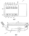
- a user inputs may include a selection of a linear or rotation position including, but not limited to: a particular measurement position 324 ; a verification position 321 (corresponding to the position of the black reference tile 70 , for example) ; a verification position 322 (corresponding to the position of a first check cell 110 , for example); a verification position 323 (corresponding to the position of a second check cell 110 , for example); and a verification position 325 (corresponding to the position of the white reference tile 80 , for example).
- the controller may be configured to be capable of running a predetermined program for periodically instructing the actuator device 25 to convey the sensor device 20 to a referencing and/or verification position as the system 1 of the present invention is conveyed (by a harvesting device H , for example) through an agricultural environment.
- the controller 5 may comprise a display 300 (such as a touch-screen display, for example) including a number of input controls 310 that may include, but are not limited to a setup button 311 (wherein a user may specify a triggering event and/or an interval after which the actuator device 25 may convey the sensor device 20 from the measurement position 100 to one or more verification positions 60 for referencing and/or validating the operation of the sensor device 20 ).
- the input controls 310 may further comprise a run button 312 allowing a user to initiate an automated and/or substantially pre-determined program of conveyance steps for referencing and/or validating the sensor device 20 .
- the display 300 of the controller 5 may further include an "NIR" or other sensor device 20 button 313 for initiating the display of a status of the sensor device 20 and/or for initiating the display of a sensor device 20 "control panel" (not shown), wherein a user may input a variety of manual adjustments to the measurement parameters of the sensor device 20 .
- the display 300 of the controller 5 may further include a "manual" button 314 wherein a user may initiate the substantially manual selection of a particular measurement position 100 and/or one or more verification positions 70 , 80 , 90 .
- the user may select the "manual" button 314 and subsequently select one of the position buttons 320 and thereby instruct the actuator device 25 to immediately convey the sensor device 20 to a selected position corresponding to one or more of the position buttons 320 (including, but not limited to: the measurement position 324 ; the verification position 321 (corresponding to the position of the black reference tile 70 , for example); the verification position 322 (corresponding to the position of a first check cell 110 , for example); the verification position 323 (corresponding to the position of a second check cell 110 , for example); and the verification position 325 (corresponding to the position of the white reference tile 80 , for example).
- a user may manually adjust the physical position of the sensor device 20 corresponding to the selection of a particular position button 320 by slidably adjusting and/or selectively securing one or more of the plurality of adjustable stops 29 corresponding to a plurality of discrete positions within the sensor device enclosure 10 (including at least one of the measuring position 100 and one or more of the verification positions 70 , 80 , 90).
- the actuator device 25 (using control inputs generated and/or received by the controller 5 , for example) may be configured to be capable of selectively and precisely conveying the sensor device 20 to one or more verification and/or referencing positions substantially adjacent a black reference tile 70 and/or substantially adjacent a white reference tile 80 .
- the sensor device 20 comprises a NIR device
- the sensor device 20 may be configured to be capable of determining the reflectance values of the reference tiles 70 , 80 to "zero" and/or "reference" the sensor device 20 .
- the actuator device 25 may be configured to be capable of conveying the sensor device 20 to a position adjacent to one or more check cells 110 , such that the sensor device 20 (comprising a NIR device, for example) may again determine a reflectance at each check cell 110 (corresponding to a "verification measurement"). The reflectance recorded from the crop sample 90 associated with each check cell 110 may then be compared with a predicted validation parameter value and, if within statistical limits, the sensor device 20 may be "validated" (i.e. determined to be operating within its specifications).
- the sensor device 20 may also be adjusted (using, for example, a sensor device 20 "control panel” accessed via the "NIR" button 313 generated by the display 300 of the controller 5 ) such that the verification parameter measured by the sensor device 20 , while the sensor device 20 is disposed in a verification position, substantially matches the known parameter of the verification device 60 .
- the actuator device 25 may then selectively move the sensor device 20 to a position adjacent to the harvested crop 50 and/or substantially above a measuring position 100 , where the sensor device 20 may be capable of measuring a quality parameter (characterized, in some embodiments, as a characteristic reflectance) of the harvested crop 50 .
- the system 1 embodiments of the present invention may comprise a sensor device enclosure 10 configured to be capable of containing the sensor device 20 in a controlled environment 30 defined by at least one environmental parameter.
- the sensor device enclosure 10 may include one or more features, individually or in combination, such that the sensor device 20 is enclosed in the controlled environment 30 defined by at least one environmental parameter, such as, for example, temperature, humidity, light, and combinations thereof.
- the sensor device enclosure 10 may comprise substantially light-reflective material 160 disposed on an outer surface of the sensor device enclosure (such as, for example, a polyurethane paint with a light reflectance value greater than 0.8) for preventing the accumulation of heat within the sensor device enclosure 10 .
- the sensor device enclosure 10 may comprise insulation material 170 (such as, for example, high-density molded expanded polystyrene, with an approximate R-value of 4) such that heat transfer between an interior of the sensor device enclosure and an exterior of the sensor device enclosure is substantially reduced and/or minimized.
- the insulation material may also comprise high R-value or "super insulating" materials (such as, for example, vacuum-insulated panels (VIPs).
- the sensor device enclosure 10 may further comprise one or more transparent portions 11 (such as, for example, a substantially transparent window) corresponding substantially to the measurement position 100 shown, for example, in FIG. 2 .
- the sensor device enclosure 10 may define one or more measurement position 100 apertures (see, for example the transparent portion 11 shown in FIG.
- the transparent portion 11 of the sensor device enclosure 10 may comprise double-pane, high R-value glass and/or polycarbonate that may allow the sensor device 20 to measure the quality parameter of the harvested crop 50 as it passes a measurement position 100 without compromising the controlled environment 30 of the interior of the sensor device enclosure 10 .
- the transparent portion 11 of the sensor device enclosure 10 may comprise a substantially scratch-resistant material including, but not limited to glass and sapphire crystal such that the harvested crop 50 and accompanying debris is less likely to scratch and/or damage the transparent portion 11 .
- an air-conditioning device 180 may be operably engaged with the sensor device enclosure 10 .
- the air conditioning device 180 may be in fluid communication with the sensor device enclosure via at vent aperture (see, for example, element 190 ) defined in the sensor device enclosure 10 .
- the air-conditioning device 180 is configured to control the at least one environmental parameter (such as temperature and/or humidity, for example).
- the sensor device enclosure 10 may further define a vent aperture 190 .
- the vent aperture 190 may be configured to be operably engaged with a conduit 175 for conveying an air flow to alter the at least one environmental parameter.
- the vent aperture 190 may be operably engaged with HVAC ducts leading to a fan and/or a dedicated air conditioning device 180 .
- the vent aperture 190 may be in fluid communication with a duct in further fluid communication with an air-conditioned interior of an operator cab C of the harvesting device H , for example.
- the sensor device enclosure 10 may include plumbing through which a coolant liquid may be introduced and/or circulated to maintain the controlled environment 30 .
- the air-conditioning device 180 may comprise a cooling device (such as a cooling plate, radiator, and/or heat sink, for example) configured to be capable of reducing a temperature within the sensor device enclosure 10 .
- Additional embodiments may further provide a method for measuring a quality parameter of a harvested crop.
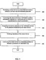
- the method first comprises step 510 for enclosing a sensor device 20 in a sensor device enclosure 10 configured to contain the sensor device 20 in a controlled environment defined by at least one environmental parameter.
- the method further comprises step 520 for conveying the sensor device 20 to a verification position substantially adjacent to a verification device 60 .
- the verification device 60 is disposed substantially within the sensor device enclosure 10 such that the sensor device 20 may be calibrated without interference from potentially error-inducing environmental conditions, including, but not limited to: high concentrations of dust, extreme temperatures, high humidity levels, and excessive ambient light levels.
- the verification device 60 disposed within the sensor device enclosure 10 is characterized by a known parameter (such as, for example, a known reflectance and/or other known quantifiable and/or identifiable physical parameter).
- the method further comprises step 530 for comparing the known parameter of the verification device 60 to a verification parameter measured by the sensor device 20 when the sensor device (and/or the verification device 60 ) is conveyed to one or more verification positions (adjacent and/or relative to one or more components of the verification device 60 , as described herein).
- Step 540 comprises verifying the operation of the sensor device 20 by controlling the lower and upper acceptable limits of the differences between the known and measured parameters of moisture and other constituent contents (step 530 , for example).
- the method embodiments of the present invention further comprise step 550 for conveying the sensor device 20 to a measuring position (see element 100 , FIG. 2 , for example) relative to the harvesting device such that the sensor device 20 is capable of measuring a quality parameter of the harvested crop 50 .
- the various conveying steps may be accomplished using an actuator device 25 configured to be capable of precisely conveying the sensor device 20 to one or more measurement and/or verification positions disposed substantially within the sensor device enclosure 10 (see FIG. 2 , for example).
- step 550 for conveying the sensor device 20 to a measuring position 100 may comprise conveying the sensor device 20 to a position substantially adjacent to a window or other substantially transparent portion 11 of the sensor device enclosure 10 (see FIG. 4 ) such that the sensor device 20 may be capable of measuring a quality parameter of a harvested crop 50 that may be conveyed adjacent to a transparent portion 11 and/or through a port defined in the sensor device enclosure 10 .
Landscapes
- Physics & Mathematics (AREA)
- Spectroscopy & Molecular Physics (AREA)
- Health & Medical Sciences (AREA)
- Life Sciences & Earth Sciences (AREA)
- Chemical & Material Sciences (AREA)
- Analytical Chemistry (AREA)
- Biochemistry (AREA)
- General Health & Medical Sciences (AREA)
- General Physics & Mathematics (AREA)
- Immunology (AREA)
- Pathology (AREA)
- Engineering & Computer Science (AREA)
- Mathematical Physics (AREA)
- Theoretical Computer Science (AREA)
- Investigating Or Analysing Materials By Optical Means (AREA)
- Combines (AREA)
Claims (15)
- System (1) zur Messung eines Qualitätsparameters einer eingebrachten Ernte, wobei das System (1) so ausgebildet ist, dass es von einer Erntevorrichtung (H) getragen wird, so dass eine Sensorvorrichtung (20) den Qualitätsparameter einer eingebrachten Ernte (50) messen kann, wobei das System (1) aufweist:ein Sensorvorrichtungsgehäuse (10), das ausgebildet ist, um die Sensorvorrichtung (20) in einer kontrollierten Umwelt (30) aufzunehmen, die durch mindestens einen Umweltparameter definiert wird;eine Prüfvorrichtung (60), wobei die Prüfvorrichtung (60) durch einen bekannten Parameter gekennzeichnet wird;eine Betätigungsvorrichtung (25), die ausgebildet ist, um die Sensorvorrichtung (20) selektiv zu einer Messposition (100) relativ zur Erntevorrichtung (H) zu transportieren, so dass die Sensorvorrichtung (20) den Qualitätsparameter der eingebrachten Ernte (50) messen kann, wobei die Betätigungsvorrichtung (25) außerdem ausgebildet ist, um die Sensorvorrichtung (20) selektiv zu einer Prüfposition im Wesentlichen benachbart der Prüfvorrichtung (60) zu transportieren, so dass die Sensorvorrichtung (20) einen Prüfparameter der Prüfvorrichtung (60) messen kann, um so eine Funktionsfähigkeit der Sensorvorrichtung (20) zu überprüfen, indem der bekannte Parameter der Prüfvorrichtung (60) mit dem von der Sensorvorrichtung (20) gemessenen Prüfparameter verglichen wird, wenn die Sensorvorrichtung (20) zur Prüfposition transportiert wird,dadurch gekennzeichnet, dass die Prüfvorrichtung (60) innerhalb des Sensorvorrichtungsgehäuses (10) angeordnet ist.
- System (1) zur Messung eines Qualitätsparameters einer eingebrachten Ernte, wobei das System (1) so ausgebildet ist, dass es von einer Erntevorrichtung (H) getragen wird, wobei das System aufweist:eine Sensorvorrichtung (20), wobei die Sensorvorrichtung (20) einen Qualitätsparameter einer eingebrachten Ernte (50) messen kann;ein Sensorvorrichtungsgehäuse (10), das ausgebildet ist, um die Sensorvorrichtung (20) in einer kontrollierten Umwelt (30) aufzunehmen, die durch mindestens einen Umweltparameter definiert wird;eine Prüfvorrichtung (60), wobei die Prüfvorrichtung (60) durch einen bekannten Parameter gekennzeichnet wird;eine Betätigungsvorrichtung (25), die ausgebildet ist, um die Sensorvorrichtung (20) selektiv zu einer Messposition (100) relativ zur Erntevorrichtung (H) zu transportieren, so dass die Sensorvorrichtung (20) den Qualitätsparameter der eingebrachten Ernte (50) messen kann, wobei die Betätigungsvorrichtung (25) außerdem ausgebildet ist, um die Sensorvorrichtung (20) selektiv zu einer Prüfposition im Wesentlichen benachbart der Prüfvorrichtung (60) zu transportieren, so dass die Sensorvorrichtung (20) einen Prüfparameter der Prüfvorrichtung (60) messen kann, um so die Sensorvorrichtung (20) zu eichen, indem der bekannte Parameter der Prüfvorrichtung (60) mit dem von der Sensorvorrichtung (20) gemessenen Prüfparameter verglichen wird, wenn die Sensorvorrichtung (20) zur Prüfposition transportiert wird,dadurch gekennzeichnet, dass die Prüfvorrichtung (60) innerhalb des Sensorvorrichtungsgehäuses (10) angeordnet ist.
- System nach Anspruch 1 oder 2, bei dem die Prüfvorrichtung (60) aus der Gruppe ausgewählt wird, die besteht aus:einer Bezugsfliese (70, 80);einer Gültigkeitsstandardernteprobe (90); undKombinationen davon.
- System nach Anspruch 3, bei dem die Bezugsfliese (70, 80) aus der Gruppe ausgewählt wird, die besteht aus:einer schwarzen Bezugsfliese (70), die durch den bekannten Parameter gekennzeichnet ist, der einen Wert des Reflexionsvermögens von im Wesentlichen Null umfaßt;eine weiße Bezugsfliese (80), die durch den bekannten Parameter gekennzeichnet ist, der einen bekannten Wert des Reflexionsvermögens von nicht Null umfasst; undKombinationen davon.
- System nach Anspruch 3, bei dem der bekannte Parameter aus der Gruppe ausgewählt wird, die besteht aus:einem Reflexionsvermögen der Prüfvorrichtung;einer Feuchtigkeit der Gültigkeitsstandardernteprobe;einem Stärkegehalt der Gültiglceitsstandardernteprobe;einem Ölgehalt der Gültigkeitsstandardernteprobe;einem Zuckergehalt der Gültigkeitsstandardernteprobe;einem Proteingehalt der Gültigkeitsstandardernteprobe;einem Verdaulichkeitsmaß der Gültigkeitsstandardernteprobe;einem NDF-Gehalt der Gültigkeitsstandardernteprobe; undKombinationen davon.
- System nach Anspruch 1 oder 2, bei dem das Sensorvorrichtungsgehäuse (10) ein im Wesentlichen lichtreflektierendes Material (160) aufweist, das auf einer Außenfläche des Sensorvorrichtungsgehäuses (10) angeordnet ist, oder bei dem das Sensorvorrichtungsgehäuse (10) ein Isoliermaterial (170) aufweist, so dass eine Wärmeübertragung zwischen dem Inneren des Sensorvorrichtungsgehäuses (10) und einer Außenseite des Sensorvorrichtungsgehäuses (10) minimiert wird.
- System nach Anspruch 1 oder 2, das außerdem eine Klimaanlage (180) aufweist, die funktionell mit dem Sensorvorrichtungsgehäuse (10) verbunden und in Fluidverbindung mit dem Sensorvorrichtungsgehäuse (10) über eine Entlüftungsöffnung (190) ist, die im Sensorvorrichtungsgehäuse (10) definiert wird, wobei die Klimaanlage (180) ausgebildet ist, um den mindestens einen Umweltparameter zu steuern.
- System nach Anspruch 1 oder 2, bei dem das Sensorvorrichtungsgehäuse (10) eine Entlüftungsöffnung (190) definiert, wobei die Entlüftungsöffnung (190) so ausgebildet ist, dass sie funktionell mit einer Leitung (175) für den Transport eines Luftstromes in Verbindung steht, um mindestens den Umweltparameter zu verändern.
- System nach Anspruch 7 oder 8, bei dem der mindestens eine Umweltparameter aus der Gruppe ausgewählt wird, die besteht aus:Temperatur; Feuchtigkeit;Lichtpegel;Staubkonzentration; undKombinationen davon.
- System nach Anspruch 1 oder 2, bei dem die Sensorvorrichtung (20) aus der Gruppe ausgewählt wird, die besteht aus:einer Nah-Infrarot-Reflexionsvorrichtung (NIR-Vorrichtung);einem Feuchtigkeitssensor;einer Sonarvorrichtung;einem Lichtsensor;einem Fotodetektor; undKombinationen davon.
- System nach Anspruch 1 oder 2, bei dem die Betätigungsvorrichtung (25) eine Betätigungsvorrichtung mit Linearbewegung für das Transportieren der Sensorvorrichtung (20) zu mindestens einer der Messposition (100) und der Prüfposition aufweist.
- System nach Anspruch 11, bei dem die Betätigungsvorrichtung (25) mit Linearbewegung einen Schneckenantrieb für das Transportieren der Sensorvorrichtung (20) zu mindestens einer der Messposition und der Prüfposition aufweist.
- System nach Anspruch 11, bei dem die Betätigungsvorrichtung (25) außerdem eine Vielzahl von einstellbaren Anschlägen (29) entsprechend einer Vielzahl von einzelnen Positionen aufweist, die mindestens eine der Messposition (100) und der Prüfposition umfassen, und bei dem die Betätigungsvorrichtung (25) mit Linearbewegung so ausgebildet ist, dass sie auf die einstellbaren Anschläge (29) anspricht, um so die Sensorvorrichtung (20) zu einer jeden der Vielzahl von einzelnen Positionen transportieren zu können.
- System nach Anspruch 1 oder 2, bei dem die Betätigungsvorrichtung (25) eine Rotationsbetätigungsvorrichtung für das Transportieren der Sensorvorrichtung (20) zu mindestens einer der Messposition (100) und der Prüfposition aufweist, das wünschenswerterweise außerdem eine zweite Betätigungsvorrichtung (35) aufweist, die ausgebildet ist, um die Prüfvorrichtung (60) relativ zur Sensorvorrichtung (20) selektiv so zu transportieren, dass die Sensorvorrichtung (20) einen oder mehrere Prüfparameter der Prüfvorrichtung (60) messen kann.
- Verfahren zur Messung eines Qualitätsparameters einer eingebrachten Ernte (50), wobei das Verfahren die folgenden Schritte aufweist:Einschließen (510) einer Sensorvorrichtung (20) in einem Sensorvorrichtungsgehäuse (10), das ausgebildet ist, um die Sensorvorrichtung (20) in einer kontrollierten Umwelt (30) aufzunehmen, die durch mindestens einen Umweltparameter definiert wird;Transportieren (520) der Sensorvorrichtung (20) zu einer Prüfposition (100) im Wesentlichen benachbart einer Prüfvorrichtung (60), wobei die Prüfvorrichtung (60) durch einen bekannten Parameter gekennzeichnet wird;Vergleichen (530) des bekannten Parameters der Prüfvorrichtung (60) mit einem von der Sensorvorrichtung (20) gemessenen Prüfparameter, um so eine Differenz dazwischen zu ermitteln, wenn die Sensorvorrichtung (20) zur Prüfposition (100) transportiert wird;Prüfen (540) der Funktion der Sensorvorrichtung (20), indem die beim Vergleichsschritt ermittelte Differenz mit einer ausgewählten oberen Grenze und einer ausgewählten unteren Grenze verglichen wird; undTransportieren (550) der Sensorvorrichtung (20) zu einer Messposition relativ zur Erntevorrichtung (H), so dass die Sensorvorrichtung (20) den Qualitätsparameter der eingebrachten Ernte (50) messen kann,dadurch gekennzeichnet, dass die Prüfvorrichtung (60) innerhalb des Sensorvorrichtungsgehäuses (10) angeordnet ist.
Applications Claiming Priority (2)
| Application Number | Priority Date | Filing Date | Title |
|---|---|---|---|
| US86647606P | 2006-11-20 | 2006-11-20 | |
| PCT/US2007/085069 WO2008064146A2 (en) | 2006-11-20 | 2007-11-19 | System and method for measuring a harvest quality parameter on a harvesting device |
Publications (2)
| Publication Number | Publication Date |
|---|---|
| EP2087341A2 EP2087341A2 (de) | 2009-08-12 |
| EP2087341B1 true EP2087341B1 (de) | 2012-04-11 |
Family
ID=39332024
Family Applications (1)
| Application Number | Title | Priority Date | Filing Date |
|---|---|---|---|
| EP07864571A Not-in-force EP2087341B1 (de) | 2006-11-20 | 2007-11-19 | System und verfahren zur messung einer erntequalitätsgrösse auf einer erntevorrichtung |
Country Status (10)
| Country | Link |
|---|---|
| US (1) | US7859674B2 (de) |
| EP (1) | EP2087341B1 (de) |
| AR (1) | AR064597A1 (de) |
| AT (1) | ATE553367T1 (de) |
| BR (1) | BRPI0718985A2 (de) |
| CA (1) | CA2670335C (de) |
| CL (1) | CL2007003328A1 (de) |
| MX (1) | MX2009005207A (de) |
| WO (1) | WO2008064146A2 (de) |
| ZA (1) | ZA200903420B (de) |
Families Citing this family (13)
| Publication number | Priority date | Publication date | Assignee | Title |
|---|---|---|---|---|
| US20090181126A1 (en) * | 2008-01-14 | 2009-07-16 | Cellencor, Inc. | Animal Feed Product From Distillers' Grain |
| WO2012141778A1 (en) | 2011-04-14 | 2012-10-18 | Pioneer Hi-Bred International, Inc. | System and method for presentation of ears of corn for image acquisition and evaluation |
| DE102015215299A1 (de) * | 2015-08-11 | 2017-02-16 | Deere & Company | Messeinrichtung zur Untersuchung geernteten Korns in einem Mähdrescher |
| JP6697964B2 (ja) * | 2016-06-27 | 2020-05-27 | 株式会社クボタ | コンバイン |
| US10169919B2 (en) * | 2016-09-09 | 2019-01-01 | Oath Inc. | Headset visual displacement for motion correction |
| DE102018103509B3 (de) * | 2017-10-11 | 2018-12-13 | Carl Zeiss Spectroscopy Gmbh | Mobiles Inhaltsstoffanalysesystem sowie Verfahren zur probenrichtigen Messung und Nutzerführung mit diesem |
| US11029713B2 (en) * | 2017-11-27 | 2021-06-08 | Liberty Reach Inc. | Method and system for expanding the range of working environments in which a 3-D or depth sensor can operate without damaging or degrading the measurement performance of the sensor |
| FI3999835T3 (fi) | 2020-01-22 | 2023-04-25 | Evonik Operations Gmbh | Menetelmä ja järjestelmä eläinperäisten, kasviperäisten tai niiden seosta olevien biologisten aineiden spektrien arvioimiseksi |
| US11647691B2 (en) * | 2020-08-17 | 2023-05-16 | Deere & Company | Close loop control of an illumination source based on sample heating |
| JP2023137889A (ja) * | 2022-03-18 | 2023-09-29 | 株式会社トプコン | 穀物成分センサ及び穀物成分分析装置 |
| US20240219363A1 (en) * | 2022-12-29 | 2024-07-04 | Agco Corporation | Sensor Placement on Swathboard of Mower |
| US20240215478A1 (en) * | 2022-12-29 | 2024-07-04 | Agco Corporation | Method for Adjusting Sensor on Swathboard of Mower |
| US20240215479A1 (en) * | 2022-12-29 | 2024-07-04 | Agco Corporation | Adjustable Sensor on Swathboard of Mower |
Family Cites Families (13)
| Publication number | Priority date | Publication date | Assignee | Title |
|---|---|---|---|---|
| US4896795A (en) * | 1988-01-15 | 1990-01-30 | Ediger Randall J | Grain moisture sensor |
| SE468334B (sv) * | 1991-04-23 | 1992-12-14 | Peter Perten | Saett och anordning foer infraroedanalys, speciellt avseende livsmedel |
| US6100526A (en) * | 1996-12-30 | 2000-08-08 | Dsquared Development, Inc. | Grain quality monitor |
| US6483583B1 (en) | 1997-02-27 | 2002-11-19 | Textron Systems Corporation | Near infrared spectrometry for real time analysis of substances |
| US5751421A (en) | 1997-02-27 | 1998-05-12 | Pioneer Hi-Bred International, Inc. | Near infrared spectrometer used in combination with a combine for real time grain analysis |
| US5991025A (en) | 1997-02-27 | 1999-11-23 | Pioneer Hi-Bred International, Inc. | Near infrared spectrometer used in combination with an agricultural implement for real time grain and forage analysis |
| EP0878704B1 (de) * | 1997-05-13 | 2005-11-09 | Gretag-Macbeth AG | Remissionsmessvorrichtung |
| US6421990B1 (en) | 1999-05-19 | 2002-07-23 | Deere & Company | Measuring device for measuring components in and/or properties of crop material |
| US6845326B1 (en) * | 1999-11-08 | 2005-01-18 | Ndsu Research Foundation | Optical sensor for analyzing a stream of an agricultural product to determine its constituents |
| DE102004010772A1 (de) | 2004-03-05 | 2005-10-06 | Deere & Company, Moline | Austrageinrichtung mit einer Messeinrichtung |
| ITBO20040160A1 (it) * | 2004-03-19 | 2004-06-19 | Dinamica Generale S R L | Apparato di analisi degli alimenti per unita' semoventi di raccolta degli alimenti |
| DE102004038408A1 (de) | 2004-08-07 | 2006-02-23 | Deere & Company, Moline | Messeinrichtung |
| DE102004048103B4 (de) * | 2004-09-30 | 2017-01-12 | Carl Zeiss Spectroscopy Gmbh | Spektrometrischer Messkopf für Erntemaschinen und andere landwirtschaftlich genutzte Maschinen |
-
2007
- 2007-11-19 US US11/942,293 patent/US7859674B2/en not_active Expired - Fee Related
- 2007-11-19 WO PCT/US2007/085069 patent/WO2008064146A2/en not_active Ceased
- 2007-11-19 EP EP07864571A patent/EP2087341B1/de not_active Not-in-force
- 2007-11-19 AT AT07864571T patent/ATE553367T1/de active
- 2007-11-19 MX MX2009005207A patent/MX2009005207A/es active IP Right Grant
- 2007-11-19 BR BRPI0718985-0A patent/BRPI0718985A2/pt not_active IP Right Cessation
- 2007-11-19 CA CA2670335A patent/CA2670335C/en not_active Expired - Fee Related
- 2007-11-20 CL CL200703328A patent/CL2007003328A1/es unknown
- 2007-11-20 AR ARP070105156A patent/AR064597A1/es not_active Application Discontinuation
-
2009
- 2009-05-19 ZA ZA200903420A patent/ZA200903420B/xx unknown
Also Published As
| Publication number | Publication date |
|---|---|
| CA2670335C (en) | 2012-08-28 |
| BRPI0718985A2 (pt) | 2014-02-11 |
| CA2670335A1 (en) | 2008-05-29 |
| US20080137087A1 (en) | 2008-06-12 |
| WO2008064146A2 (en) | 2008-05-29 |
| MX2009005207A (es) | 2009-05-28 |
| AR064597A1 (es) | 2009-04-15 |
| US7859674B2 (en) | 2010-12-28 |
| ZA200903420B (en) | 2010-06-30 |
| CL2007003328A1 (es) | 2008-06-20 |
| WO2008064146A3 (en) | 2008-07-10 |
| EP2087341A2 (de) | 2009-08-12 |
| ATE553367T1 (de) | 2012-04-15 |
Similar Documents
| Publication | Publication Date | Title |
|---|---|---|
| CA2670335C (en) | System and method for measuring a harvest quality parameter on a harvesting device | |
| AU2008200572B2 (en) | Near infrared sensor combined with camera | |
| US5957773A (en) | Method and apparatus for measuring grain characteristics | |
| AU2005218054B2 (en) | Spectrometric measuring head for harvesting machines and other equipment used in agriculture | |
| KR102317446B1 (ko) | 광학식 곡립 평가 장치 및, 상기 광학식 곡립 평가 장치를 구비한 콤바인 | |
| US4971077A (en) | On-line tobacco evaluation system and method | |
| EP1481224B1 (de) | Vorrichtung und verfahren zur bereitstellung von räumlich selektiven online-massen- oder -volumenmessungen hergestellter artikel | |
| RU2492453C2 (ru) | Способ и устройство для анализа и разделения зерна | |
| Maertens et al. | On-line measurement of grain quality with NIR technology | |
| AU2018218356B2 (en) | Spectrometric probe for sampling bulk material and automatic sample taker for sampling including the probe | |
| EP1237401B1 (de) | System zum messen von bestandteilen | |
| US20050188859A1 (en) | Production meat analysis system and method | |
| EP1894461A1 (de) | System zur Echtzeit-Analyse von Silagefutter | |
| US6749810B2 (en) | Method and apparatus for presenting grain for NIR spectography examination | |
| WO2009143921A1 (en) | A method for determining an optical property of an optical layer | |
| CN112255189A (zh) | 烟草物料在线水分仪调节方法以及装置 | |
| US20080231853A1 (en) | Qualitative Analysis System and Method for Agricultural Products in Harvesting Equipment | |
| JPH0238959A (ja) | サンプリング茶葉の計測部構造 | |
| JPH10288582A (ja) | 殻粒判別装置 | |
| EP2128603A1 (de) | Verfahren zur Bestimmung einer optischen Eigenschaft einer optischen Schicht | |
| WO2025196622A1 (en) | Sorter devices, detections systems of sorter devices, and related methods | |
| JPH0238943A (ja) | 中揉機におけるサンプリング装置の取付方法 | |
| JPS6142099Y2 (de) | ||
| JPH06308023A (ja) | 共同乾燥施設における生籾の仕分け方法 | |
| JPH0829338A (ja) | 葉菜類の鮮度評価装置 |
Legal Events
| Date | Code | Title | Description |
|---|---|---|---|
| PUAI | Public reference made under article 153(3) epc to a published international application that has entered the european phase |
Free format text: ORIGINAL CODE: 0009012 |
|
| 17P | Request for examination filed |
Effective date: 20090427 |
|
| AK | Designated contracting states |
Kind code of ref document: A2 Designated state(s): AT BE BG CH CY CZ DE DK EE ES FI FR GB GR HU IE IS IT LI LT LU LV MC MT NL PL PT RO SE SI SK TR |
|
| 17Q | First examination report despatched |
Effective date: 20091008 |
|
| DAX | Request for extension of the european patent (deleted) | ||
| GRAP | Despatch of communication of intention to grant a patent |
Free format text: ORIGINAL CODE: EPIDOSNIGR1 |
|
| RIC1 | Information provided on ipc code assigned before grant |
Ipc: G01N 21/35 20060101ALI20111124BHEP Ipc: G01N 21/27 20060101AFI20111124BHEP Ipc: A01D 41/127 20060101ALI20111124BHEP |
|
| RAP1 | Party data changed (applicant data changed or rights of an application transferred) |
Owner name: PIONEER HI-BRED INTERNATIONAL INC. |
|
| RIN1 | Information on inventor provided before grant (corrected) |
Inventor name: GRETEN, WILHELM G. Inventor name: HILDEBRAND, CARLOS Inventor name: WELLE, ROLAND |
|
| RAP1 | Party data changed (applicant data changed or rights of an application transferred) |
Owner name: PIONEER-HI-BRED INTERNATIONAL, INC. |
|
| GRAS | Grant fee paid |
Free format text: ORIGINAL CODE: EPIDOSNIGR3 |
|
| GRAA | (expected) grant |
Free format text: ORIGINAL CODE: 0009210 |
|
| AK | Designated contracting states |
Kind code of ref document: B1 Designated state(s): AT BE BG CH CY CZ DE DK EE ES FI FR GB GR HU IE IS IT LI LT LU LV MC MT NL PL PT RO SE SI SK TR |
|
| REG | Reference to a national code |
Ref country code: GB Ref legal event code: FG4D |
|
| REG | Reference to a national code |
Ref country code: CH Ref legal event code: EP |
|
| REG | Reference to a national code |
Ref country code: AT Ref legal event code: REF Ref document number: 553367 Country of ref document: AT Kind code of ref document: T Effective date: 20120415 |
|
| REG | Reference to a national code |
Ref country code: IE Ref legal event code: FG4D |
|
| REG | Reference to a national code |
Ref country code: DE Ref legal event code: R096 Ref document number: 602007022027 Country of ref document: DE Effective date: 20120606 |
|
| REG | Reference to a national code |
Ref country code: NL Ref legal event code: T3 |
|
| REG | Reference to a national code |
Ref country code: AT Ref legal event code: MK05 Ref document number: 553367 Country of ref document: AT Kind code of ref document: T Effective date: 20120411 |
|
| LTIE | Lt: invalidation of european patent or patent extension |
Effective date: 20120411 |
|
| PG25 | Lapsed in a contracting state [announced via postgrant information from national office to epo] |
Ref country code: FI Free format text: LAPSE BECAUSE OF FAILURE TO SUBMIT A TRANSLATION OF THE DESCRIPTION OR TO PAY THE FEE WITHIN THE PRESCRIBED TIME-LIMIT Effective date: 20120411 Ref country code: CY Free format text: LAPSE BECAUSE OF FAILURE TO SUBMIT A TRANSLATION OF THE DESCRIPTION OR TO PAY THE FEE WITHIN THE PRESCRIBED TIME-LIMIT Effective date: 20120411 Ref country code: IS Free format text: LAPSE BECAUSE OF FAILURE TO SUBMIT A TRANSLATION OF THE DESCRIPTION OR TO PAY THE FEE WITHIN THE PRESCRIBED TIME-LIMIT Effective date: 20120811 Ref country code: LT Free format text: LAPSE BECAUSE OF FAILURE TO SUBMIT A TRANSLATION OF THE DESCRIPTION OR TO PAY THE FEE WITHIN THE PRESCRIBED TIME-LIMIT Effective date: 20120411 Ref country code: PL Free format text: LAPSE BECAUSE OF FAILURE TO SUBMIT A TRANSLATION OF THE DESCRIPTION OR TO PAY THE FEE WITHIN THE PRESCRIBED TIME-LIMIT Effective date: 20120411 Ref country code: SE Free format text: LAPSE BECAUSE OF FAILURE TO SUBMIT A TRANSLATION OF THE DESCRIPTION OR TO PAY THE FEE WITHIN THE PRESCRIBED TIME-LIMIT Effective date: 20120411 |
|
| PG25 | Lapsed in a contracting state [announced via postgrant information from national office to epo] |
Ref country code: GR Free format text: LAPSE BECAUSE OF FAILURE TO SUBMIT A TRANSLATION OF THE DESCRIPTION OR TO PAY THE FEE WITHIN THE PRESCRIBED TIME-LIMIT Effective date: 20120712 Ref country code: PT Free format text: LAPSE BECAUSE OF FAILURE TO SUBMIT A TRANSLATION OF THE DESCRIPTION OR TO PAY THE FEE WITHIN THE PRESCRIBED TIME-LIMIT Effective date: 20120813 Ref country code: LV Free format text: LAPSE BECAUSE OF FAILURE TO SUBMIT A TRANSLATION OF THE DESCRIPTION OR TO PAY THE FEE WITHIN THE PRESCRIBED TIME-LIMIT Effective date: 20120411 Ref country code: SI Free format text: LAPSE BECAUSE OF FAILURE TO SUBMIT A TRANSLATION OF THE DESCRIPTION OR TO PAY THE FEE WITHIN THE PRESCRIBED TIME-LIMIT Effective date: 20120411 |
|
| PG25 | Lapsed in a contracting state [announced via postgrant information from national office to epo] |
Ref country code: BE Free format text: LAPSE BECAUSE OF FAILURE TO SUBMIT A TRANSLATION OF THE DESCRIPTION OR TO PAY THE FEE WITHIN THE PRESCRIBED TIME-LIMIT Effective date: 20120411 |
|
| PG25 | Lapsed in a contracting state [announced via postgrant information from national office to epo] |
Ref country code: EE Free format text: LAPSE BECAUSE OF FAILURE TO SUBMIT A TRANSLATION OF THE DESCRIPTION OR TO PAY THE FEE WITHIN THE PRESCRIBED TIME-LIMIT Effective date: 20120411 Ref country code: AT Free format text: LAPSE BECAUSE OF FAILURE TO SUBMIT A TRANSLATION OF THE DESCRIPTION OR TO PAY THE FEE WITHIN THE PRESCRIBED TIME-LIMIT Effective date: 20120411 Ref country code: CZ Free format text: LAPSE BECAUSE OF FAILURE TO SUBMIT A TRANSLATION OF THE DESCRIPTION OR TO PAY THE FEE WITHIN THE PRESCRIBED TIME-LIMIT Effective date: 20120411 Ref country code: DK Free format text: LAPSE BECAUSE OF FAILURE TO SUBMIT A TRANSLATION OF THE DESCRIPTION OR TO PAY THE FEE WITHIN THE PRESCRIBED TIME-LIMIT Effective date: 20120411 Ref country code: SK Free format text: LAPSE BECAUSE OF FAILURE TO SUBMIT A TRANSLATION OF THE DESCRIPTION OR TO PAY THE FEE WITHIN THE PRESCRIBED TIME-LIMIT Effective date: 20120411 Ref country code: RO Free format text: LAPSE BECAUSE OF FAILURE TO SUBMIT A TRANSLATION OF THE DESCRIPTION OR TO PAY THE FEE WITHIN THE PRESCRIBED TIME-LIMIT Effective date: 20120411 |
|
| PLBE | No opposition filed within time limit |
Free format text: ORIGINAL CODE: 0009261 |
|
| STAA | Information on the status of an ep patent application or granted ep patent |
Free format text: STATUS: NO OPPOSITION FILED WITHIN TIME LIMIT |
|
| 26N | No opposition filed |
Effective date: 20130114 |
|
| REG | Reference to a national code |
Ref country code: DE Ref legal event code: R097 Ref document number: 602007022027 Country of ref document: DE Effective date: 20130114 |
|
| REG | Reference to a national code |
Ref country code: CH Ref legal event code: PL |
|
| GBPC | Gb: european patent ceased through non-payment of renewal fee |
Effective date: 20121119 |
|
| PG25 | Lapsed in a contracting state [announced via postgrant information from national office to epo] |
Ref country code: CH Free format text: LAPSE BECAUSE OF NON-PAYMENT OF DUE FEES Effective date: 20121130 Ref country code: LI Free format text: LAPSE BECAUSE OF NON-PAYMENT OF DUE FEES Effective date: 20121130 Ref country code: BG Free format text: LAPSE BECAUSE OF FAILURE TO SUBMIT A TRANSLATION OF THE DESCRIPTION OR TO PAY THE FEE WITHIN THE PRESCRIBED TIME-LIMIT Effective date: 20120711 |
|
| REG | Reference to a national code |
Ref country code: IE Ref legal event code: MM4A |
|
| PG25 | Lapsed in a contracting state [announced via postgrant information from national office to epo] |
Ref country code: IE Free format text: LAPSE BECAUSE OF NON-PAYMENT OF DUE FEES Effective date: 20121119 Ref country code: ES Free format text: LAPSE BECAUSE OF FAILURE TO SUBMIT A TRANSLATION OF THE DESCRIPTION OR TO PAY THE FEE WITHIN THE PRESCRIBED TIME-LIMIT Effective date: 20120722 |
|
| PG25 | Lapsed in a contracting state [announced via postgrant information from national office to epo] |
Ref country code: GB Free format text: LAPSE BECAUSE OF NON-PAYMENT OF DUE FEES Effective date: 20121119 Ref country code: MT Free format text: LAPSE BECAUSE OF FAILURE TO SUBMIT A TRANSLATION OF THE DESCRIPTION OR TO PAY THE FEE WITHIN THE PRESCRIBED TIME-LIMIT Effective date: 20120411 |
|
| PG25 | Lapsed in a contracting state [announced via postgrant information from national office to epo] |
Ref country code: MC Free format text: LAPSE BECAUSE OF NON-PAYMENT OF DUE FEES Effective date: 20121130 Ref country code: TR Free format text: LAPSE BECAUSE OF FAILURE TO SUBMIT A TRANSLATION OF THE DESCRIPTION OR TO PAY THE FEE WITHIN THE PRESCRIBED TIME-LIMIT Effective date: 20120411 |
|
| PG25 | Lapsed in a contracting state [announced via postgrant information from national office to epo] |
Ref country code: LU Free format text: LAPSE BECAUSE OF NON-PAYMENT OF DUE FEES Effective date: 20121119 |
|
| PG25 | Lapsed in a contracting state [announced via postgrant information from national office to epo] |
Ref country code: HU Free format text: LAPSE BECAUSE OF FAILURE TO SUBMIT A TRANSLATION OF THE DESCRIPTION OR TO PAY THE FEE WITHIN THE PRESCRIBED TIME-LIMIT Effective date: 20071119 |
|
| REG | Reference to a national code |
Ref country code: FR Ref legal event code: PLFP Year of fee payment: 9 |
|
| PGFP | Annual fee paid to national office [announced via postgrant information from national office to epo] |
Ref country code: DE Payment date: 20151110 Year of fee payment: 9 Ref country code: IT Payment date: 20151124 Year of fee payment: 9 |
|
| PGFP | Annual fee paid to national office [announced via postgrant information from national office to epo] |
Ref country code: NL Payment date: 20151110 Year of fee payment: 9 Ref country code: FR Payment date: 20151008 Year of fee payment: 9 |
|
| REG | Reference to a national code |
Ref country code: DE Ref legal event code: R119 Ref document number: 602007022027 Country of ref document: DE |
|
| REG | Reference to a national code |
Ref country code: NL Ref legal event code: MM Effective date: 20161201 |
|
| REG | Reference to a national code |
Ref country code: FR Ref legal event code: ST Effective date: 20170731 |
|
| PG25 | Lapsed in a contracting state [announced via postgrant information from national office to epo] |
Ref country code: NL Free format text: LAPSE BECAUSE OF NON-PAYMENT OF DUE FEES Effective date: 20161201 |
|
| PG25 | Lapsed in a contracting state [announced via postgrant information from national office to epo] |
Ref country code: FR Free format text: LAPSE BECAUSE OF NON-PAYMENT OF DUE FEES Effective date: 20161130 Ref country code: IT Free format text: LAPSE BECAUSE OF NON-PAYMENT OF DUE FEES Effective date: 20161119 |
|
| PG25 | Lapsed in a contracting state [announced via postgrant information from national office to epo] |
Ref country code: DE Free format text: LAPSE BECAUSE OF NON-PAYMENT OF DUE FEES Effective date: 20170601 |