EP2087970B1 - Découpeur de films - Google Patents
Découpeur de films Download PDFInfo
- Publication number
- EP2087970B1 EP2087970B1 EP20090152215 EP09152215A EP2087970B1 EP 2087970 B1 EP2087970 B1 EP 2087970B1 EP 20090152215 EP20090152215 EP 20090152215 EP 09152215 A EP09152215 A EP 09152215A EP 2087970 B1 EP2087970 B1 EP 2087970B1
- Authority
- EP
- European Patent Office
- Prior art keywords
- knife
- film cutter
- degrees
- plastic sheet
- inclination
- Prior art date
- Legal status (The legal status is an assumption and is not a legal conclusion. Google has not performed a legal analysis and makes no representation as to the accuracy of the status listed.)
- Not-in-force
Links
- 238000005520 cutting process Methods 0.000 claims description 18
- 230000001105 regulatory effect Effects 0.000 claims description 6
- 230000004044 response Effects 0.000 claims description 2
- 239000002985 plastic film Substances 0.000 description 35
- 229920003023 plastic Polymers 0.000 description 28
- 230000000694 effects Effects 0.000 description 6
- 238000004519 manufacturing process Methods 0.000 description 6
- 238000003475 lamination Methods 0.000 description 5
- 239000000463 material Substances 0.000 description 3
- 239000000853 adhesive Substances 0.000 description 2
- 230000001070 adhesive effect Effects 0.000 description 2
- 230000002411 adverse Effects 0.000 description 2
- 230000008901 benefit Effects 0.000 description 2
- 230000001276 controlling effect Effects 0.000 description 2
- 238000003780 insertion Methods 0.000 description 2
- 230000037431 insertion Effects 0.000 description 2
- 239000005026 oriented polypropylene Substances 0.000 description 2
- -1 polyethylene terephthalate Polymers 0.000 description 2
- 229920000139 polyethylene terephthalate Polymers 0.000 description 2
- 239000005020 polyethylene terephthalate Substances 0.000 description 2
- 230000009467 reduction Effects 0.000 description 2
- 230000008030 elimination Effects 0.000 description 1
- 238000003379 elimination reaction Methods 0.000 description 1
- 230000006872 improvement Effects 0.000 description 1
- 238000010030 laminating Methods 0.000 description 1
- 230000007246 mechanism Effects 0.000 description 1
- 238000000034 method Methods 0.000 description 1
- 230000004048 modification Effects 0.000 description 1
- 238000012986 modification Methods 0.000 description 1
- 230000008569 process Effects 0.000 description 1
- 238000011144 upstream manufacturing Methods 0.000 description 1
Images


Classifications
-
- B—PERFORMING OPERATIONS; TRANSPORTING
- B26—HAND CUTTING TOOLS; CUTTING; SEVERING
- B26D—CUTTING; DETAILS COMMON TO MACHINES FOR PERFORATING, PUNCHING, CUTTING-OUT, STAMPING-OUT OR SEVERING
- B26D3/00—Cutting work characterised by the nature of the cut made; Apparatus therefor
- B26D3/28—Splitting layers from work; Mutually separating layers by cutting
-
- B—PERFORMING OPERATIONS; TRANSPORTING
- B26—HAND CUTTING TOOLS; CUTTING; SEVERING
- B26D—CUTTING; DETAILS COMMON TO MACHINES FOR PERFORATING, PUNCHING, CUTTING-OUT, STAMPING-OUT OR SEVERING
- B26D1/00—Cutting through work characterised by the nature or movement of the cutting member or particular materials not otherwise provided for; Apparatus or machines therefor; Cutting members therefor
- B26D1/01—Cutting through work characterised by the nature or movement of the cutting member or particular materials not otherwise provided for; Apparatus or machines therefor; Cutting members therefor involving a cutting member which does not travel with the work
- B26D1/04—Cutting through work characterised by the nature or movement of the cutting member or particular materials not otherwise provided for; Apparatus or machines therefor; Cutting members therefor involving a cutting member which does not travel with the work having a linearly-movable cutting member
- B26D1/06—Cutting through work characterised by the nature or movement of the cutting member or particular materials not otherwise provided for; Apparatus or machines therefor; Cutting members therefor involving a cutting member which does not travel with the work having a linearly-movable cutting member wherein the cutting member reciprocates
- B26D1/10—Cutting through work characterised by the nature or movement of the cutting member or particular materials not otherwise provided for; Apparatus or machines therefor; Cutting members therefor involving a cutting member which does not travel with the work having a linearly-movable cutting member wherein the cutting member reciprocates in, or substantially in, a direction parallel to the cutting edge
- B26D1/105—Cutting through work characterised by the nature or movement of the cutting member or particular materials not otherwise provided for; Apparatus or machines therefor; Cutting members therefor involving a cutting member which does not travel with the work having a linearly-movable cutting member wherein the cutting member reciprocates in, or substantially in, a direction parallel to the cutting edge for thin material, e.g. for sheets, strips or the like
-
- Y—GENERAL TAGGING OF NEW TECHNOLOGICAL DEVELOPMENTS; GENERAL TAGGING OF CROSS-SECTIONAL TECHNOLOGIES SPANNING OVER SEVERAL SECTIONS OF THE IPC; TECHNICAL SUBJECTS COVERED BY FORMER USPC CROSS-REFERENCE ART COLLECTIONS [XRACs] AND DIGESTS
- Y10—TECHNICAL SUBJECTS COVERED BY FORMER USPC
- Y10T—TECHNICAL SUBJECTS COVERED BY FORMER US CLASSIFICATION
- Y10T83/00—Cutting
- Y10T83/647—With means to convey work relative to tool station
- Y10T83/664—Roller
-
- Y—GENERAL TAGGING OF NEW TECHNOLOGICAL DEVELOPMENTS; GENERAL TAGGING OF CROSS-SECTIONAL TECHNOLOGIES SPANNING OVER SEVERAL SECTIONS OF THE IPC; TECHNICAL SUBJECTS COVERED BY FORMER USPC CROSS-REFERENCE ART COLLECTIONS [XRACs] AND DIGESTS
- Y10—TECHNICAL SUBJECTS COVERED BY FORMER USPC
- Y10T—TECHNICAL SUBJECTS COVERED BY FORMER US CLASSIFICATION
- Y10T83/00—Cutting
- Y10T83/687—By tool reciprocable along elongated edge
- Y10T83/6875—With means permitting tool to be rotatably adjusted about its cutting edge during cutting
-
- Y—GENERAL TAGGING OF NEW TECHNOLOGICAL DEVELOPMENTS; GENERAL TAGGING OF CROSS-SECTIONAL TECHNOLOGIES SPANNING OVER SEVERAL SECTIONS OF THE IPC; TECHNICAL SUBJECTS COVERED BY FORMER USPC CROSS-REFERENCE ART COLLECTIONS [XRACs] AND DIGESTS
- Y10—TECHNICAL SUBJECTS COVERED BY FORMER USPC
- Y10T—TECHNICAL SUBJECTS COVERED BY FORMER US CLASSIFICATION
- Y10T83/00—Cutting
- Y10T83/929—Tool or tool with support
Definitions
- a laminator is defined as a laminated plate employable for production of a name-tag, certificate, passport, license certificate or the like.
- the laminator is a laminated plate made by laminating a transparent plate on a paper or the like on which letters and/or pictures are printed or written.
- the film cutter (un-numbered) comprises two sets of roller type feeder means (7) for feeding a long planar plate covered by transparent plastic sheet (4) in the direction shown by an arrow (D), a traverse means (8) for traversing a knife (10) made of a thin, narrow and plane rectangular planar blade which is placed along the top surface of the long planar plate covered by transparent plastic sheet (4) to be inserted between the ends (1a) and (1b) of the neighboring quadrilateral plates (1) for the final purpose to cut the transparent plastic sheet (3) along the end (1b) of the upper one of the quadrilateral plates (1) and to produce a unit of lamination of a transparent plastic sheet (3) and a quadrilateral plate (1), the unit further representing each unit of the letters and/or pictures printed or written on the quadrilateral plate.
- Figs. 3 and 4 respectively show the side view and the plan view of a long planar plate (2) which is a series of plural quadrilateral plates (1) standing on different levels with their ends overlapped. Small areas (1aa) and (1bb), each of which is close, respectively, to one of the ends (1a) and (1b) of the quadrilateral plate (1) such as paper or the like having a size of A-4, just for example, on which letters and/or pictures are printed or written, overlap resulting in the long planar plate (2).
- each end (1a) of the quadrilateral plate (1) overlaps respective end (1b) of the quadrilateral plate (1), and that the small area (1aa) close to the end (1a) is not adhered to the small area (1bb) close to the end (1b).
- an extremely thin slit which will be referred to as (1d) remains between the small area (1aa) and the small area (1bb) to allow a knife (10) to be inserted therein or between the upper and lower quadrilateral plates (1).
- Figs. 5 and 6 respectively show the side view and the plan view of a long planar plate laminated by a transparent plastic sheet (4).
- the next step is to cover the long planar plates (2) with a transparent plastic sheet (3) which is made from polyethylene terephthalate, oriented polypropylene or the like and has a width shorter than the width of the long planar plates (2), resultantly making a long planar plate laminated by a transparent plastic sheet (4).
- a transparent plastic sheet (3) which is made from polyethylene terephthalate, oriented polypropylene or the like and has a width shorter than the width of the long planar plates (2), resultantly making a long planar plate laminated by a transparent plastic sheet (4).
- the final step to be described referring to Figs. 1 and 2 is that the transparent plastic sheet (3) is cut at each location where the ends (1a) and (1b) of the neighboring quadrilateral plates (1) overlap.
- the final step is to separate each unit from the laminated transparent plastic sheet (4).
- the purpose of the film cutter available in the prior art is to separate each unit of letters and/or pictures printed or written on the continued quadrilateral plates (1) and protected by a single transparent long plastic sheet (3).
- the film cutter has 2 sets of roller type feeder means (7) having a function to feed the long planar plate laminated by transparent plastic sheet (4) in the direction shown by an arrow (D), and a traverse means (8) for traversing a knife (10) across the long planar plate laminated by transparent plastic sheet (4).
- an extremely thin slit (1d) exists between the small area (1bb) of the end (1b) of the upper quadrilateral plates (1) and the small area (1aa) of the end (1a) of the lower quadrilateral plates (1).
- the width of the transparent long plastic sheet (3) is required to be shorter than the width of the quadrilateral plates (1) to facilitate insertion of the knife (10) in the extremely thin slit (1d) between the ends (1a) and (1b) of the quadrilateral plates (1).
- the knife (10) can be inserted between the ends (1a) and (1b) of the neighboring quadrilateral plates (1) and cut the transparent plastic sheet (3) across the entire width of the transparent plastic sheet (3) to separate individual units of plural lamination of a transparent plastic sheet (3) and the quadrilateral plate (1), the unit representing each unit of the letters and/or pictures printed or written on the long planar plates (2).
- the first one of the drawbacks is that because it is difficult to insert the knife (10) in the extremely thin slit (1d) between the small area (1bb) of the end (1b) of the upper piece of the quadrilateral plate (1) and the small area (1aa) of the end (1a) of the lower piece of the quadrilateral plates (1) (See Fig. 3 .), it is necessary equip the cutter with additional means to push downward the lateral edge of the lower piece of the quadrilateral plate (1) and to push upward the lateral edge of the upper piece of the quadrilateral plate (1).
- the inefficiency of using the additional means is clear.
- a film cutter in the sense of the preamble of claim 1 is known. That film cutter has two knifes being placed in a downward inclined position. Also in this known film cutter it is disadvantageous that the vertical position at which the knife contacts the thin slit between two adjacent short plates varies as a consequence of the linear feeding movement of the planar body comprising plural short plates.
- the object of this invention is to provide a film cutter free from the drawbacks elaborated above.
- the present invention proposes a film cutter having the features of claim 1.
- the film cutter has an inclined orientation of the knife (6).
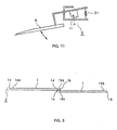
- a feature applicable to the position of the knife (6) is a downward inclination of the knife (6), wherein the cutting point is lower in the upstream direction with regard to the direction of movement D, as shown in Fig. 9 .
- the preferable angle of inclination of the knife (6) relative to the long plastic sheet (3) is between about 2 degrees and about 16 degrees.
- a further feature is application of a downward inclination of the knife (6), wherein the initial amount of inclination is selected at a small amount (e.g. 2 degrees) and the inclination is gradually increased and the cutting point of the knife (6) advances downward to keep the height of the cutting point at the initial height, regardless the progress of the feeder (7) and traverse.
- a small amount e.g. 2 degrees
- the maximum amount of inclination can be selected from the foregoing range of about 2 degrees and about 16 degrees.
- Additional features of the film cutter relate to the shape (configuration) of the knife.
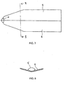
- the first additional feature applicable to the shape of the knife (6) is to make the general shape of the knife that of a rectangle that is longer in its length, narrower in its width, thinner in its thickness that has a sharp, pointed end, as illustrated in Fig. 7 .
- a two-stage reduction of the width toward the pointed end as shown in Fig. 7 is preferable.
- the preferable thickness of the knife (6) is 0.3 mm.
- the preferable magnitude of the inner angle (14) of the point of the knife (6) is in the range of about 70 degrees through 110 degrees, as shown in Fig. 7 .
- the width of the knife (6) is about 60mm and the overall length is about 160mm.
- the second additional applicable to the shape of the knife (6) is to make the cross-section of the knife (6) in a V-shape or convex when viewed from the bottom of the knife (6) (i.e., convex to the film) as shown in Fig. 8 .
- the magnitude of the angle (5) between the two parts of the knife is in the range of about 90 degrees to about 170 degrees.
- Fig. 1 is a side view of a film cutter available in the prior art.
- Fig. 2 is a plan view of a film cutter available in the prior art.
- Fig. 3 is a side view of a long planar plate produced by piling a plate above another in succession, available in the prior art and of this invention.
- Fig. 4 is a plan view of a long planar plate produced by piling a plate above another in succession, available in the prior art and of this invention.
- Fig. 5 is a side view of a long planar plate laminated by a transparent plastic sheet, available in the prior art and of this invention.
- Fig. 6 is a plan view of a long planar plate laminated by a transparent plastic sheet, available in the prior art and of this invention.
- Fig. 7 is a plan view of a knife employed for this invention.
- Fig. 8 is a cross-section of a knife employed for this invention taken along line 8-8- of figure 7 .
- Fig. 9 is a side view of a film cutter of an embodiment of this invention.
- Fig. 10 is a plan view of a film cutter of the second emdodiment of this invention.
- Fig. 11 is a side view of a means for regulating the inclination of the knife in response to the progress of the feeder means of this invention.
- Figs. 3 and 4 respectively show the side view and the plan view of a long planar plate (2) which is a series of overlapping quadrilateral plates (1) produced by overlapping one plate with a succeeding plate in succession.
- the long planar plate (2) is employed as a material plate for production of a laminator which is further a material plate for production of a name tag, certificate, passport, license plate or the like.
- the quadrilateral plates (1) are of uniform size and each bears letters and/or pictures printed or written thereon. Since the long planar plate (2) is entirely identical to that employed in the prior art, any further description is unnecessary.
- Figs. 5 and 6 respectively show the side view and the plan view of a long planar plate laminated by a transparent plastic sheet (4).
- This long planar plate laminated by a transparent plastic sheet (4) is a lamination made by covering the foregoing long planar plate (2) with a transparent long plastic sheet (3), which is preferably made from polyethylene terephthalate, oriented polypropylene or the like.
- the width of the transparent long plastic sheet (3) is less than that of the long planar plates laminated by a transparent plastic sheet (2) and the single transparent long plastic sheet (3) is adhered to plural quadrilateral plates (1). Since the long planar plate laminated by a transparent plastic sheet (4) is entirely identical to that of the prior art, any further description is unnecessary.
- Figs. 7 and 8 respectively show the plan view and the cross section of a knife (6) created just for this invention.
- the body thereof shown in the right portion of Fig. 7 is of uniform width which is made gradually smaller to reach the sharp cutting point shown in the left portion of the same drawing.
- the two-step reduction in width has shown advantageous experimental results.
- the preferable thickness of the knife (6) is about 0.3mm.
- the preferable dihedral angle (5) of the V-shaped knife (6) is in the range of about 90 through 170 degrees.
- Figs. 9 and 10 respectively is a side view and a plan view of a film cutter of an embodiment of this invention.
- the knife (6) is arranged in a downwardly inclined position, keeping the point at a lowest position, as shown in Fig. 9 .
- the angle of inclination (16) is illustrated in Fig. 9 .
- the film cutter (un-numbered) comprises two sets of roller type feed means (7) having a function to feed the long planar plate laminated by transparent plastic sheet (4) in the direction shown by an arrow (D), a traverse means (8) for traversing a knife (6) which is inserted between the ends (1a) and (1b) of the neighboring quadrilateral plates (1) for the final purpose to cut the transparent plastic sheet (3) and to produce individual units of lamination of a transparent long plastic sheet (3) and the quadrilateral plate (1) which is equivalent to units of the letters and/or pictures printed on the quadrilateral plates (1).
- the embodiment shown in Figs. 9 and 10 realizes a remarkable advantage in the convenience of inserting the knife (6) between the ends (1a) and (1b) of the neighboring quadrilateral plates (1).
- a drawback arises wherein the height at which the cutting is actually occurs gradually increases, or moves upward, following the traverse process of the knife (6).
- the feeder means typically continues advancing the long planar plate as the knife traverses the long planar plate (2) in the cutting operation.
- the moving planar plate will push against the angled knife and potentially stall the movement of the plate, thus adversely affecting the cutting operation.
- the second feature of the described embodiment of this invention is, however, effective to overcome the foregoing drawbacks.
- Fig. 11 illustrates a means (9) for controlling the angle of inclination of the knife (6), for maintaining the height at which the knife (6) contacts the extremely thin slit (1d) fixed, despite the fact that the location where the knife (6) contacts the extremely thin slit (1d) moves because of the function of the feeder means (7). Moreover, allowing the angle of inclination to increase effectives prevents stalling engagement between the long planar plate and the knife.
- means (9) automatically regulates the downward inclination of the knife (6), to maintain the vertical position at which the knife (6) contacts the extremely thin slit (1d), regardless the progress of the long planar plate covered by transparent plastic sheet (4) driven by the feeder means (7) in the direction D. Since the location where the knife (6) contacts the extremely thin slit (1d) is the location where the cutting activity is realized, the height at which the knife (6) contacts the extremely thin slit (1d) is automatically regulated at a predetermined height. Regardless of the progress of the long planar plate covered by transparent plastic sheet (4) driven by the feeder means (7), the cutting activity is not disturbed, despite the fact that the cutting location moves in the direction of the arrow D. As well, the feeder means is not jammed by engagement between the advancing long planar plate and the angled knife.
- the function of the means (9) is to balance of the weight of the knife (6) and the strength of a spring (91) for maintaining unchanged the height at which the knife (6) contacts the extremely thin slit (1d), by increasing the downward inclination of the knife (6).
- This function is realized by balancing the knife (6) by employment of a spring (91).
- the principle of the means 9 for regulating the inclination of the knife 6 in the embodiment shown is that the spring 91 will allow the cutting point of knife 6 engaged with the thin slit 1d between the ends 1bb and 1aa to move downward as the laminate 4 moves forward in the direction D.
- the inclination of the knife 6 automatically adjusts for relative movement between laminate 4 and knife 6 resulting in the inclination of the knife 6 increasing during progress of the traverse, but the height of the engagement between the knife and the transparent sheet 3 remains constant.
- Fig. 11 shows a side view of a means 9 in accordance with a preferred embodiment of the invention for regulating the inclination of the knife 6.
- the traverse means 8 includes a transversely movable knife support 11, which is driven across the laminate 4 during cutting by known drive means, which is not illustrated.
- the knife 6 is pivotally mounted to the support 11, as by a pivot axle 12, whereby the angle of inclination of the knife is adjustable.
- the inclination of the knife with respect to the support 11 and, in turn, the laminate 4 is controlled by spring 91, but other mechanisms for controlling the angle of inclination may be used.
Landscapes
- Life Sciences & Earth Sciences (AREA)
- Forests & Forestry (AREA)
- Engineering & Computer Science (AREA)
- Mechanical Engineering (AREA)
- Laminated Bodies (AREA)
- Making Paper Articles (AREA)
- Nonmetal Cutting Devices (AREA)
Claims (6)
- Dispositif à découper les films comprenant :un ensemble de moyens d'alimentation (7) pour alimenter un corps planaire comprenant plusieurs plaques courtes se chevauchant partiellement, ledit corps planaire étant couvert d'une feuille transparente (4),un couteau (6) comportant une lame rectangulaire se prolongeant en un point de coupe aigu, ledit couteau (6) étant placé dans une position inclinée vers le bas sur la surface supérieure du niveau inférieur dudit corps planaire superposé, ledit couteau (6) devant être inséré dans une fente mince (1d) se trouvant entre le niveau supérieur et le niveau inférieur dudit corps planaire superposé, ledit couteau (6) étant traversé par un moyen de traverse (8) pour découper ladite feuille transparente (4) en suivant une partie linéaire reliant lesdites plusieurs plaques courtes se chevauchant,caractérisé par le fait
qu'il comprend également un moyen (9) pour régler l'amplitude de l'inclinaison de ladite position inclinée vers le bas en réponse à la progression réalisée par ledit moyen d'alimentation (7). - Dispositif à découper les films selon la revendication 1, dans lequel l'amplitude de l'angle dudit couteau à point de coupe aigu (6) se situe dans une fourchette allant de 70 degrés à 110 degrés.
- Dispositif à découper les films selon l'une quelconque des revendications précédentes, dans lequel ledit couteau (6) présente une coupe transversale en forme de V.
- Dispositif à découper les films selon l'une quelconque des revendications précédentes, dans lequel l'épaisseur dudit couteau (6) est approximativement égale à 0,3 mm.
- Dispositif à découper les films selon la revendication 3 ou 4, dans lequel l'angle intérieur du couteau en forme de V se situe dans une fourchette comprise entre 90 degrés et 170 degrés.
- Dispositif à découper les films selon l'une quelconque des revendications précédentes, dans lequel l'amplitude de ladite inclinaison vers le bas est sélectionnée de façon à être d'approximativement 10 degrés au miment du démarrage, et est sélectionnée dans une fourchette allant approximativement de 10 à 16 degrés pour la suite.
Applications Claiming Priority (1)
| Application Number | Priority Date | Filing Date | Title |
|---|---|---|---|
| JP2008024663A JP2009184045A (ja) | 2008-02-05 | 2008-02-05 | 被膜切断装置。 |
Publications (2)
| Publication Number | Publication Date |
|---|---|
| EP2087970A1 EP2087970A1 (fr) | 2009-08-12 |
| EP2087970B1 true EP2087970B1 (fr) | 2010-10-13 |
Family
ID=40668301
Family Applications (1)
| Application Number | Title | Priority Date | Filing Date |
|---|---|---|---|
| EP20090152215 Not-in-force EP2087970B1 (fr) | 2008-02-05 | 2009-02-05 | Découpeur de films |
Country Status (5)
| Country | Link |
|---|---|
| US (1) | US20090211423A1 (fr) |
| EP (1) | EP2087970B1 (fr) |
| JP (1) | JP2009184045A (fr) |
| CN (1) | CN101502966A (fr) |
| DE (1) | DE602009000260D1 (fr) |
Families Citing this family (1)
| Publication number | Priority date | Publication date | Assignee | Title |
|---|---|---|---|---|
| CN102152327B (zh) * | 2010-11-30 | 2012-10-17 | 厦门亚太创新机器有限公司 | 薄膜切割机 |
Family Cites Families (21)
| Publication number | Priority date | Publication date | Assignee | Title |
|---|---|---|---|---|
| US532822A (en) * | 1895-01-22 | Emil saltzkorn and ludwig nicolai | ||
| US734444A (en) * | 1903-03-19 | 1903-07-21 | Samuel Stenger | Goods-exhibitor. |
| US2225630A (en) * | 1938-07-29 | 1940-12-24 | Craftsman Equipment Corp | Scoring device for sample paper boxes |
| US3213779A (en) * | 1963-06-19 | 1965-10-26 | Lois H First | Spatula |
| DE2151526A1 (de) * | 1971-10-15 | 1973-04-19 | Schulte August | Vorrichtung fuer die entfernung von etiketten |
| US3882747A (en) * | 1974-08-12 | 1975-05-13 | Othmar Carli | Dimensionally and angularly adjustable template device for interior corner cutting of picture frame mats |
| JPS6135933A (ja) * | 1984-07-28 | 1986-02-20 | Kyuichiro Kudo | 枚葉式ラミネ−タ−装置におけるフイルムカツタ−機構 |
| US4619169A (en) * | 1985-10-02 | 1986-10-28 | D&K Custom Machine Design, Inc. | Cutter mechanism for laminate slitting machine |
| EP0225505B1 (fr) * | 1985-11-12 | 1991-12-27 | Somar Corporation | Dispositif pour l'enlèvement d'un film |
| NL8800077A (nl) * | 1988-01-14 | 1989-08-01 | Vmi Epe Holland | Inrichting voor het doorsnijden van een strook ongevulcaniseerde rubber. |
| CA2015979C (fr) * | 1990-05-03 | 1997-10-07 | Robert Deaver | Dispositif pour peler une bande de transporteur |
| US5271305A (en) * | 1992-05-26 | 1993-12-21 | The Fletcher-Terry Company | Base and clamping bar assembly |
| JP3349171B2 (ja) * | 1992-07-09 | 2002-11-20 | 日本ケミコン株式会社 | ラミネート枚葉紙のカッター構造 |
| JP3412920B2 (ja) * | 1994-08-24 | 2003-06-03 | 株式会社エム・シー・ケー | ラミネータ |
| US6311783B1 (en) * | 1999-03-08 | 2001-11-06 | William Harpell | Gardening tool |
| JP3385510B2 (ja) * | 2000-05-08 | 2003-03-10 | 株式会社不二鉄工所 | フィルム切断装置ならびに切断方法 |
| JP2002184315A (ja) * | 2000-12-11 | 2002-06-28 | Sony Corp | フイルム剥離装置及び剥離方法 |
| US7200939B2 (en) * | 2001-02-26 | 2007-04-10 | Bridgestone Corporation | Device for ripping gum of conveyor belt |
| JP2002345834A (ja) * | 2001-05-25 | 2002-12-03 | Manii Kk | 医療用刃物 |
| KR100633488B1 (ko) * | 2001-11-08 | 2006-10-13 | 샤프 가부시키가이샤 | 유리 기판의 분단 방법, 유리 기판의 분단 장치 및 액정 패널 제조 장치 |
| DE202006006208U1 (de) * | 2006-04-13 | 2007-08-23 | Kiersch Composite Gmbh | Schneidvorrichtung |
-
2008
- 2008-02-05 JP JP2008024663A patent/JP2009184045A/ja active Pending
-
2009
- 2009-02-03 CN CNA2009100061447A patent/CN101502966A/zh active Pending
- 2009-02-04 US US12/320,748 patent/US20090211423A1/en not_active Abandoned
- 2009-02-05 DE DE200960000260 patent/DE602009000260D1/de active Active
- 2009-02-05 EP EP20090152215 patent/EP2087970B1/fr not_active Not-in-force
Also Published As
| Publication number | Publication date |
|---|---|
| CN101502966A (zh) | 2009-08-12 |
| DE602009000260D1 (de) | 2010-11-25 |
| US20090211423A1 (en) | 2009-08-27 |
| EP2087970A1 (fr) | 2009-08-12 |
| JP2009184045A (ja) | 2009-08-20 |
Similar Documents
| Publication | Publication Date | Title |
|---|---|---|
| US7101332B2 (en) | Sheet folding and trimming apparatus | |
| US20020168247A1 (en) | Binding system with sheet-wise formation of features | |
| EP1849619B1 (fr) | Appareil de broyage | |
| EP2406159B1 (fr) | Dispositif de transfert pour support plan dans une machine de production d'emballages | |
| US8453547B2 (en) | Method and device for trimming at least one side edge of a bound printed product | |
| EP1858788B1 (fr) | Dispositif d'alimentation feuille a feuille | |
| EP2087970B1 (fr) | Découpeur de films | |
| EP2189290B1 (fr) | Systèmes et procédé de fabrication et d'empilage d'étiquettes | |
| ATE345909T1 (de) | Vorrichtung zum dreiseitlichem schneiden von blattmaterialstapeln | |
| US5451041A (en) | Sheet feeder of a printing press | |
| EP3470347A1 (fr) | Procédé et machine d'emballage destinés à la fabrication d'emballages groupés | |
| US10967534B2 (en) | Scrap scraper | |
| US20140178153A1 (en) | Paper sheet having a hinge adjacent to its spine edge, a plurality of the sheets being bound into a book whereby the sheets lay flat when the book opened | |
| US8776660B2 (en) | Detachable sheet | |
| AU2795600A (en) | Gather-stitcher machine and method for producing a header index for print materials or papers which are filed by means of a gather-stitcher machine | |
| US20060169120A1 (en) | Serrated utility knife blade | |
| JP3606734B2 (ja) | 製本装置 | |
| CN1144733A (zh) | 切角器 | |
| HK1060484A2 (en) | A die-cutting razor for die-cutting folding ruled lines on sheets | |
| US7197971B2 (en) | Device for trimming sheet material | |
| JP3180329U (ja) | シート状部材の打ち抜き型及び仕切り体 | |
| US20040020340A1 (en) | Book trimmer and trimmer blade | |
| DE69827089T2 (de) | Verfahren und Vorrichtung zum Transportieren von Produkten in Blattform | |
| JPH09315030A (ja) | 製本装置 | |
| US8646367B2 (en) | Trimmer block pad, trimmer, and method of trimming |
Legal Events
| Date | Code | Title | Description |
|---|---|---|---|
| PUAI | Public reference made under article 153(3) epc to a published international application that has entered the european phase |
Free format text: ORIGINAL CODE: 0009012 |
|
| AK | Designated contracting states |
Kind code of ref document: A1 Designated state(s): AT BE BG CH CY CZ DE DK EE ES FI FR GB GR HR HU IE IS IT LI LT LU LV MC MK MT NL NO PL PT RO SE SI SK TR |
|
| AX | Request for extension of the european patent |
Extension state: AL BA RS |
|
| 17P | Request for examination filed |
Effective date: 20100121 |
|
| 17Q | First examination report despatched |
Effective date: 20100212 |
|
| AKX | Designation fees paid |
Designated state(s): DE ES FR GB IT NL |
|
| GRAP | Despatch of communication of intention to grant a patent |
Free format text: ORIGINAL CODE: EPIDOSNIGR1 |
|
| GRAS | Grant fee paid |
Free format text: ORIGINAL CODE: EPIDOSNIGR3 |
|
| GRAA | (expected) grant |
Free format text: ORIGINAL CODE: 0009210 |
|
| AK | Designated contracting states |
Kind code of ref document: B1 Designated state(s): DE ES FR GB IT NL |
|
| REG | Reference to a national code |
Ref country code: GB Ref legal event code: FG4D |
|
| REG | Reference to a national code |
Ref country code: NL Ref legal event code: T3 |
|
| REF | Corresponds to: |
Ref document number: 602009000260 Country of ref document: DE Date of ref document: 20101125 Kind code of ref document: P |
|
| PGFP | Annual fee paid to national office [announced via postgrant information from national office to epo] |
Ref country code: DE Payment date: 20110225 Year of fee payment: 3 Ref country code: FR Payment date: 20110301 Year of fee payment: 3 |
|
| PG25 | Lapsed in a contracting state [announced via postgrant information from national office to epo] |
Ref country code: ES Free format text: LAPSE BECAUSE OF FAILURE TO SUBMIT A TRANSLATION OF THE DESCRIPTION OR TO PAY THE FEE WITHIN THE PRESCRIBED TIME-LIMIT Effective date: 20110124 |
|
| PLBE | No opposition filed within time limit |
Free format text: ORIGINAL CODE: 0009261 |
|
| STAA | Information on the status of an ep patent application or granted ep patent |
Free format text: STATUS: NO OPPOSITION FILED WITHIN TIME LIMIT |
|
| 26N | No opposition filed |
Effective date: 20110714 |
|
| REG | Reference to a national code |
Ref country code: DE Ref legal event code: R097 Ref document number: 602009000260 Country of ref document: DE Effective date: 20110714 |
|
| PG25 | Lapsed in a contracting state [announced via postgrant information from national office to epo] |
Ref country code: IT Free format text: LAPSE BECAUSE OF FAILURE TO SUBMIT A TRANSLATION OF THE DESCRIPTION OR TO PAY THE FEE WITHIN THE PRESCRIBED TIME-LIMIT Effective date: 20101013 |
|
| REG | Reference to a national code |
Ref country code: NL Ref legal event code: V1 Effective date: 20120901 |
|
| REG | Reference to a national code |
Ref country code: FR Ref legal event code: ST Effective date: 20121031 |
|
| REG | Reference to a national code |
Ref country code: DE Ref legal event code: R119 Ref document number: 602009000260 Country of ref document: DE Effective date: 20120901 |
|
| PG25 | Lapsed in a contracting state [announced via postgrant information from national office to epo] |
Ref country code: NL Free format text: LAPSE BECAUSE OF NON-PAYMENT OF DUE FEES Effective date: 20120901 Ref country code: FR Free format text: LAPSE BECAUSE OF NON-PAYMENT OF DUE FEES Effective date: 20120229 |
|
| PG25 | Lapsed in a contracting state [announced via postgrant information from national office to epo] |
Ref country code: DE Free format text: LAPSE BECAUSE OF NON-PAYMENT OF DUE FEES Effective date: 20120901 |
|
| REG | Reference to a national code |
Ref country code: GB Ref legal event code: 732E Free format text: REGISTERED BETWEEN 20170921 AND 20170927 |
|
| PGFP | Annual fee paid to national office [announced via postgrant information from national office to epo] |
Ref country code: GB Payment date: 20180221 Year of fee payment: 10 |
|
| GBPC | Gb: european patent ceased through non-payment of renewal fee |
Effective date: 20190205 |
|
| PG25 | Lapsed in a contracting state [announced via postgrant information from national office to epo] |
Ref country code: GB Free format text: LAPSE BECAUSE OF NON-PAYMENT OF DUE FEES Effective date: 20190205 |