EP2088026A2 - Bewegliches System mit Linearmotor - Google Patents
Bewegliches System mit Linearmotor Download PDFInfo
- Publication number
- EP2088026A2 EP2088026A2 EP09001105A EP09001105A EP2088026A2 EP 2088026 A2 EP2088026 A2 EP 2088026A2 EP 09001105 A EP09001105 A EP 09001105A EP 09001105 A EP09001105 A EP 09001105A EP 2088026 A2 EP2088026 A2 EP 2088026A2
- Authority
- EP
- European Patent Office
- Prior art keywords
- movable body
- zone
- coordinate
- travel route
- route
- Prior art date
- Legal status (The legal status is an assumption and is not a legal conclusion. Google has not performed a legal analysis and makes no representation as to the accuracy of the status listed.)
- Granted
Links
Images


Classifications
-
- B—PERFORMING OPERATIONS; TRANSPORTING
- B65—CONVEYING; PACKING; STORING; HANDLING THIN OR FILAMENTARY MATERIAL
- B65G—TRANSPORT OR STORAGE DEVICES, e.g. CONVEYORS FOR LOADING OR TIPPING, SHOP CONVEYOR SYSTEMS OR PNEUMATIC TUBE CONVEYORS
- B65G43/00—Control devices, e.g. for safety, warning or fault-correcting
- B65G43/08—Control devices operated by article or material being fed, conveyed or discharged
-
- B—PERFORMING OPERATIONS; TRANSPORTING
- B60—VEHICLES IN GENERAL
- B60L—PROPULSION OF ELECTRICALLY-PROPELLED VEHICLES; SUPPLYING ELECTRIC POWER FOR AUXILIARY EQUIPMENT OF ELECTRICALLY-PROPELLED VEHICLES; ELECTRODYNAMIC BRAKE SYSTEMS FOR VEHICLES IN GENERAL; MAGNETIC SUSPENSION OR LEVITATION FOR VEHICLES; MONITORING OPERATING VARIABLES OF ELECTRICALLY-PROPELLED VEHICLES; ELECTRIC SAFETY DEVICES FOR ELECTRICALLY-PROPELLED VEHICLES
- B60L13/00—Electric propulsion for monorail vehicles, suspension vehicles or rack railways; Magnetic suspension or levitation for vehicles
-
- B—PERFORMING OPERATIONS; TRANSPORTING
- B65—CONVEYING; PACKING; STORING; HANDLING THIN OR FILAMENTARY MATERIAL
- B65G—TRANSPORT OR STORAGE DEVICES, e.g. CONVEYORS FOR LOADING OR TIPPING, SHOP CONVEYOR SYSTEMS OR PNEUMATIC TUBE CONVEYORS
- B65G1/00—Storing articles, individually or in orderly arrangement, in warehouses or magazines
- B65G1/02—Storage devices
- B65G1/04—Storage devices mechanical
- B65G1/137—Storage devices mechanical with arrangements or automatic control means for selecting which articles are to be removed
Definitions
- the present invention relates to a movable body system using a linear motor.
- the present invention relates a technique of determining a coordinate of a movable body relative to a travel route.
- movable bodies are moved using a linear motor having a primary side on the ground, and a secondary side on each of the movable bodies.
- a linear motor having a primary side on the ground, and a secondary side on each of the movable bodies.
- LSM linear synchronous motor
- Coils are provided on the ground, and secondary members such as magnets and magnetizable material are provided on the movable bodies.
- the travel route is divided into a plurality of zones, and the linear motor is controlled by a zone controller provided for each zone.
- Patent Publication 1 JP2002-337037A proposes a technique of detecting a position of a movable body using a linear scale.
- An object of the invention is to allow a plurality of movable bodies to travel in each zone by detecting coordinates of the movable bodies on a travel route using the existing sensor.
- the present invention relate to a movable body system including primary coils of a linear motor arranged along a travel route, and a movable body having a secondary side of the linear motor.
- the travel route is divided into a plurality of zones.
- Each of the zones has a zone controller for controlling the coils in the zone.
- Each of the coils has a linear scale.
- the zone controller has coordinate calculation means for converting a coordinate of the movable body based on the linear scale outputted from the linear scale, into a coordinate based on the travel route.
- means for determining a distance between movable bodies by means of the coordinate based on the travel route determined by the coordinate calculation means is provided for allowing a plurality of movable bodies to travel in one zone.
- the movable body has an ID, and at least one ID reader is provided in each zone for reading the ID of the movable body in the zone.
- the coordinate based on the travel route includes an ID of a sub-route as a part of the travel route, and a coordinate in the sub-route.
- a method of controlling a movable body system includes the steps of arranging primary coils of a linear motor along a travel route, the primary coils each having a linear scale; providing a movable body on the travel route, the movable body having a secondary side of the linear motor; dividing the travel route into a plurality of zones, and providing a zone controller for controlling the coils of the linear motor in each zone; converting a coordinate of the movable body based on the linear scale outputted from the linear scale, into a coordinate based on the travel route; and controlling the coils of the linear motor by the zone controller, by means of the coordinate based on the travel route.
- description regarding the movable body system is directly applicable to the method of controlling the movable body system.
- a coordinate based on a linear scale is converted into a coordinate based on a travel route to determine a position of a movable body objectively. In this manner, a distance between movable bodies can be determined, and a plurality of movable bodies can travel in one zone.
- FIGS. 1 to 7 show a movable body system according to an embodiment.
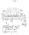
- FIG. 1 shows a basic concept of the embodiment.
- a travel route is divided into a plurality of zones 1 to 6.
- the zones 1 to 4 are inter-bay routes
- the zones 5 and 6 are intra-bay routes.
- the inter-bay route is a main or parent sub-route
- the intra-bay route is a branch or child sub-route.
- each of the sub-routes is formed in a loop, and the routes are interconnected by transit lines 24.
- Zone controllers C1 to C6 are provided for the respective zones, and the zone controllers C1 to C6 are controlled by a controller 30 that controls the entire system. Part of the travel route of the zone 1 is enlarged on a lower side in FIG. 1 .
- primary coils 42 of a linear motor are arranged at a predetermined pitch along the travel route.
- Movable bodies 44 each having a linear motor secondary magnet moves along the travel route.
- Each coil 42 has a linear scale 43.
- the controller C1 or the like stores an offset of the coils 42 in each travel route in the coordinate system in units of sub-routes, and adds the offset and a coordinate from the linear scale to determine the coordinate in the sub-route.
- the zone controller C1 or the like determines the position of the movable body in the sub-route, converts it into an absolute coordinate with additional information such as an ID and a type of the sub-route, and outputs the absolute position to nearby zone controllers and the controller 30.
- the arrangement pitch of the coils 42 is shorter than a measurement span determined by combination of the movable body 44 and the linear scale 43 so that the coordinate of the movable body 44 can be measured seamlessly without any gap.
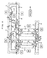
- FIG. 2 shows a layout of the movable body system.
- Zones 1 to 4, and zone 8 and 9 form a main loop 20 having two traffic lanes.
- zones 14 and 15 form a main loop 21 having one traffic lane.
- Zones 12 and 13 form intra-bay routes 22.
- Dot-dash lines in the drawing denote boundaries between zones.
- Reference numerals 24 denote transit lines connecting the intra-bay routes 22 to the main loops 20, 21.
- traffic lanes are connected by the main loop 20 having the two traffic lanes.
- Reference numerals 26 denote shortcuts for allowing travel along the loops 20, 21 in a short period of time.
- the controllers C1 to C15 control associated zones. At least one of the ID reader I1 to I48 is provided in each zone to read IDs of movable bodies. In the embodiment, the ID readers I1 to I45 are provided at entrances of the zones and at positions upstream of diverge segments. Alternatively, the ID readers I1 to I45 may be provided for each of coils of the linear motor. Arrows in FIG. 2 show travel directions of the movable bodies.
- FIG. 3 shows a layout of ID readers and transit lines 24 in the zone 1 as an example.
- the ID readers are provided at the entrances of the zones and at positions before the diverge segments.
- an ID of the movable body can be read by the ID reader.
- the ID can be read at the position before the diverge segment for controlling the movable body to move straight or move into the diverge segment.
- a mechanical mechanism controls the movable body to move into a diverge segment or a merge segment.
- the linear motor may control the movable body to move into the diverge segment or the merge segment.
- Reference numerals D 1 to D4 denote diverge apparatuses
- reference numerals M1 to M3 denote merge apparatuses provided at respective diverge segments and merge segments in FIG. 2 .
- a reference numeral 32 denotes a bus for connecting the controller 30 and the zone controller C1 or the like.
- the controller 30 or the like sends transportation instructions to the zone controller C 1 or the like, and the zone controller C 1 or the like reports the current position and the speed of the movable body at the absolute coordinate to the controller 30. Further, the zone controller C1 or the like notifies the limit speed at the zone boundary to the zone controller on the upstream side. Based on the limit speed at the zone boundary, the zone controller on the upstream side restricts the speed of the movable body.
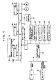
- FIG. 4 shows a layout of the linear scales 43 and structure of the zone controller.
- the movable body 44 has a magnet 45 such as a permanent magnet, and travels synchronously with the traveling magnetic field from the coils 42.
- the gravity is supported by wheels (not shown) or the like.
- the linear scale 43 and the magnetic pole sensor 47 are formed integrally with, e.g., the coils 42, and the number of magnetic poles of the magnet 45 is counted by the magnetic pole sensor 47.
- the linear scale 43 detects the phase or the like of the magnet 45 relative to the linear scale 43, and combines the detected data with a signal from the magnetic pole sensor 47 to determine the position of the magnetic object 44 based on the linear scale 43.
- the movable body 44 has an ID 46 such as an RFID or a barcode, and the ID 46 is read by an ID reader I1 or the like.
- a reference numeral 40 denotes a power line
- a reference numeral 41 denotes a signal line.
- the zone controller C1 or the like controls the coils 42 through the signal line 41, and receives data from the linear scales 43 and the ID reader.
- the coils 42 are energized through the power line 40.
- the zone controller C1 or the like controls a transfer apparatus 50 or the like provided in a station, and controls the diverge apparatus D1, and the merge apparatus M1 or the like.
- Each of the zone controllers such as the zone controller C1 has an absolute coordinate calculation unit 51.
- the signal from the linear scale 43 includes an ID of the coil 42.
- the absolute coordinate calculation unit 51 has a table for converting the ID of the coil to an ID of a sub-route to which the coil belongs, and an offset based on the origin of the sub-route. By adding the offset to the coordinate from the linear scale 43, and adding data such as the ID and the type of the sub-route to which the linear scale belongs, an absolute coordinate for uniquely identifying the position of the movable body 44 over the entire travel route is obtained.
- the types of the travel route include a large-scale main loop, a medium-scale main loop, an intra-bay route, and a transit line.
- a target speed setting unit 52 sets a target speed of the movable body 44.
- An upper limit of the travel speed is defined for each segment having a size corresponding to, e.g., a pitch of arranging the coils 42. Then, by the distance between the movable bodies 44, a limit speed for preventing interference is determined. The speed at which a trailing movable body can avoid interference even if a leading movable body is decelerated at the maximum deceleration is determined as the limit speed. Further, each of the zone controllers notifies the limit speed at the zone boundary to the zone controller on the upstream side.
- the upper limit speed at the zone boundary is the maximum speed for entry of the movable body from the zone on the upstream side without any interference with the movable body 44 in the zone on the downstream side, and for allowing the movable body to pass through the exit of the zone on the downstream side within a limit speed range.
- the zone controller on the upstream side Upon receiving a notification of the limit speed at the zone boundary, the zone controller on the upstream side takes the limit speed at the zone boundary into consideration, instead of taking the position and speed of the movable body in the zone on the downstream side into consideration.
- the process in the zone controller on the upstream side can be carried out easily.
- the motor control unit 53 controls the coils 42 as primary coils of the linear motor.
- the transfer control unit 54 controls operation of the transfer apparatus 50 relative to the movable body 44 stopped at a station, and controls operation of the transfer apparatus 50.
- a divergence control unit 55 controls the diverge apparatus D1, the merge apparatus M1 or the like to control diverging and merging of the movable bodies 44.
- the zone controller C1 or the like has a communication unit 56 for communicating with the other zone controller C2 or the like, and the controller 30 through the bus 32. Communication between the zone controllers include notification of the limit speed to the zone controller on the upstream side, and notification of data such as an ID and a destination of the entered movable body. In the case of communication between the controller 30 and zone controller C1 or the like, the absolute coordinate and the speed of the movable body are notified from the zone controller C1 or the like to the controller 30. The controller 30 notifies the ID of the movable body and the travel instruction to the zone controller C 1 or the like. The travel instruction includes a list of IDs of movable bodies, destinations, and sub-routes leading to the destinations.
- FIG. 5 shows absolute coordinate data 60 to 62.
- the data 60 is data for the large-scale main loop. As a type, for example, "0" is assigned to the first one bit, and an ID of a route and a coordinate in the route are described in the data 60.
- Data 61 is used for the medium-scale main loop. For example, the type of the data 61 is expressed by "10" in two bits, and an ID of a route and a coordinate of the route is described in the data 60.
- the data 62 is used for the intra-bay route and the transit line. The type of the data 62 is "11" in two bits, and an ID of a route and a coordinate in the route are described in the data 62.
- the data 60 to 62 have a common data length. Further, in the same sub-route, if the current position is determined, the distance to a forward position can be determined. If the entire length of the route is determined, the distance or interval to a backward position is the same route can be determined.
- a reference numeral 64 denotes a route table.
- data of the route table 4 may be stored in the controller 30, and additionally in the zone controllers C1 to C15.
- FIG. 6 shows data in the route table 64 for one sub-route.
- FIG. 6 shows the ID and the type of the route, and the entire length of the route.
- One sub-route includes one or more connection origin routes and connection destination routes.
- the connection origin means the upstream side
- the connection destination means the downstream side.
- the ID of the route, and both of the connection origin coordinate and the connection destination coordinate are described as the coordinate of the connection position. In this manner, arbitral positions on the entire travel route, and distances between arbitral positions can be determined.
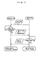
- FIG. 7 shows an algorithm at the time when the movable body moves from a zone on the upstream side to a zone on the downstream side.
- the zone controller on the upstream side notifies the limit speed at the zone boundary, e.g., at predetermined time interval.
- the zone controller on the upstream side restricts the speed of the movable body in order to prevent problems such as interference of with the leading movable body when the trailing movable body enters the zone on the downstream side.
- the ID and the destination of the movable body are notified from the zone controller on the upstream side to the zone controller on the downstream side.
- the zone controller on the downstream side can carry out the process for preparation of the arrival of the movable body.
- the ID of the movable body is detected by the ID reader at the entrance of the zone, the arrival of the movable body and the ID are notified to the zone controller on the upstream side.
- the movable body which has moved to the downstream side is deleted from targets controlled by the zone controller on the upstream side, and added to targets controlled by the zone controller on the downstream side.
- movable bodies for transportation of articles has been described in the embodiment, movable bodies of any types may be used. Further, types of the used linear motor are not limited to the linear synchronization motor.
Landscapes
- Engineering & Computer Science (AREA)
- Mechanical Engineering (AREA)
- Physics & Mathematics (AREA)
- Electromagnetism (AREA)
- Power Engineering (AREA)
- Transportation (AREA)
- Control Of Position, Course, Altitude, Or Attitude Of Moving Bodies (AREA)
- Control Of Linear Motors (AREA)
- Linear Motors (AREA)
- Control Of Vehicles With Linear Motors And Vehicles That Are Magnetically Levitated (AREA)
Applications Claiming Priority (1)
| Application Number | Priority Date | Filing Date | Title |
|---|---|---|---|
| JP2008025935A JP5093664B2 (ja) | 2008-02-06 | 2008-02-06 | 移動体システム |
Publications (3)
| Publication Number | Publication Date |
|---|---|
| EP2088026A2 true EP2088026A2 (de) | 2009-08-12 |
| EP2088026A3 EP2088026A3 (de) | 2014-07-02 |
| EP2088026B1 EP2088026B1 (de) | 2017-12-06 |
Family
ID=40718895
Family Applications (1)
| Application Number | Title | Priority Date | Filing Date |
|---|---|---|---|
| EP09001105.7A Active EP2088026B1 (de) | 2008-02-06 | 2009-01-27 | Bewegliches System mit Linearmotor |
Country Status (6)
| Country | Link |
|---|---|
| US (1) | US7945357B2 (de) |
| EP (1) | EP2088026B1 (de) |
| JP (1) | JP5093664B2 (de) |
| KR (1) | KR101301167B1 (de) |
| CN (1) | CN101504547B (de) |
| TW (1) | TWI437398B (de) |
Cited By (4)
| Publication number | Priority date | Publication date | Assignee | Title |
|---|---|---|---|---|
| EP2786946A1 (de) * | 2013-04-04 | 2014-10-08 | Knapp AG | Magnetfördertechnik für ein Transportsystem |
| EP2292461A3 (de) * | 2009-09-08 | 2014-10-15 | Murata Machinery, Ltd. | Bewegliches Fahrzeugsystem und Verfahren zur Steuerung sich bewegender Fahrzeuge |
| WO2015036197A1 (de) * | 2013-09-13 | 2015-03-19 | Krones Ag | Vorrichtung und verfahren zum transport von behältern in einer behälterbehandlungsanlage |
| EP2779432B1 (de) | 2011-11-07 | 2016-06-15 | Yamaha Hatsudoki Kabushiki Kaisha | Linearförderer |
Families Citing this family (19)
| Publication number | Priority date | Publication date | Assignee | Title |
|---|---|---|---|---|
| US8483895B1 (en) * | 2009-02-25 | 2013-07-09 | James J. Beregi | Transportation system, system components and process |
| JP4941790B2 (ja) * | 2009-08-28 | 2012-05-30 | 村田機械株式会社 | 移動体システム |
| JP5077717B2 (ja) * | 2010-04-12 | 2012-11-21 | 村田機械株式会社 | 磁極検出システム |
| JP5146855B2 (ja) * | 2010-08-09 | 2013-02-20 | 村田機械株式会社 | 天井走行車システム |
| JP2014229026A (ja) * | 2013-05-21 | 2014-12-08 | キヤノン株式会社 | 情報処理装置、情報処理方法、及びプログラム |
| CN103786595B (zh) * | 2014-01-16 | 2015-12-09 | 南车株洲电力机车有限公司 | 悬浮控制节点网络的网关控制器及控制系统 |
| IL230866A0 (en) * | 2014-02-06 | 2014-09-30 | Dan Yehuda Schlesinger | Device for surface transportation |
| US10591890B2 (en) | 2016-07-06 | 2020-03-17 | Industrial Technology Research Institute | Localization device using magnetic field and positioning method thereof |
| FR3063983A1 (fr) * | 2017-03-17 | 2018-09-21 | C.E.R.M.E.X. Constructions Etudes Et Recherches De Materiels Pour L'emballage D'expedition | Dispositif de transfert d'objets |
| TWI629225B (zh) * | 2017-08-28 | 2018-07-11 | 台達電子工業股份有限公司 | 輸送系統 |
| CN109422079B (zh) | 2017-08-28 | 2021-05-07 | 台达电子工业股份有限公司 | 输送系统 |
| TWI634404B (zh) * | 2017-09-13 | 2018-09-01 | Industrial Technology Research Institute | 利用磁力場形之定位及姿態估測方法及其系統與包含有該方法之電腦可讀取記錄媒體 |
| EP3599127B1 (de) * | 2018-07-25 | 2022-10-05 | B&R Industrial Automation GmbH | Verfahren zum betreiben eines langstatorlinearmotors mit transporteinheiten und kollisionsüberwachung |
| CN110941258A (zh) * | 2018-09-21 | 2020-03-31 | 日本电产株式会社 | 移动体的控制方法及移动体的控制系统 |
| TWI687650B (zh) | 2018-11-14 | 2020-03-11 | 財團法人工業技術研究院 | 利用磁力場形之定位及姿態估測方法及其系統 |
| KR102489221B1 (ko) * | 2020-12-21 | 2023-01-17 | 세메스 주식회사 | 위치 측정기 및 이를 포함하는 기판 처리 장치 |
| WO2023135936A1 (ja) * | 2022-01-12 | 2023-07-20 | 住友重機械工業株式会社 | 駆動装置、駆動方法、駆動プログラム |
| CN116394976A (zh) * | 2023-04-03 | 2023-07-07 | 博雷顿科技股份公司 | 一种基于相对坐标系自动驾驶循迹轨迹点生成方法 |
| CN117775741B (zh) * | 2024-01-25 | 2024-07-23 | 苏州纵苇科技有限公司 | 设备移动方法、装置、设备、存储介质和程序产品 |
Citations (1)
| Publication number | Priority date | Publication date | Assignee | Title |
|---|---|---|---|---|
| JP2002337037A (ja) | 2001-05-11 | 2002-11-26 | Murata Mach Ltd | 移動体の位置検出制御装置 |
Family Cites Families (25)
| Publication number | Priority date | Publication date | Assignee | Title |
|---|---|---|---|---|
| JPH0847111A (ja) * | 1994-08-02 | 1996-02-16 | Toshiba Corp | 搬送システム |
| US5801462A (en) * | 1995-03-31 | 1998-09-01 | Minolta Co., Ltd. | Linear motor and image reading apparatus |
| JPH09261943A (ja) * | 1996-03-22 | 1997-10-03 | Nippon Thompson Co Ltd | リニアモータ駆動装置 |
| US5864833A (en) * | 1996-12-23 | 1999-01-26 | Philips Electronics North American Corp. | Apparatus for optimizing the layout and charge maps of a flowline of pick and place machines |
| US6764266B2 (en) * | 1999-07-29 | 2004-07-20 | Young Richard C | Robotic parts handler system |
| JP2000191140A (ja) * | 1998-12-26 | 2000-07-11 | Minebea Co Ltd | リニアモ―タを用いた搬送システム |
| US6590355B1 (en) * | 1999-06-07 | 2003-07-08 | Nikon Corporation | Linear motor device, stage device, and exposure apparatus |
| JP4094799B2 (ja) * | 2000-06-22 | 2008-06-04 | 日本トムソン株式会社 | 可動マグネット型リニアモータを内蔵したスライド装置 |
| JP2002321699A (ja) * | 2001-04-27 | 2002-11-05 | Mitsubishi Heavy Ind Ltd | 航空貨物搬送システム |
| JP2003029836A (ja) * | 2001-07-12 | 2003-01-31 | Toyota Industries Corp | シャトル型搬送車の位置算出方法、シャトル型搬送車の運行制御方法及びシャトル型搬送車 |
| US7134258B2 (en) * | 2001-12-05 | 2006-11-14 | R.A. Jones & Co. Inc. | Packaging apparatus and methods |
| US20040148763A1 (en) * | 2002-12-11 | 2004-08-05 | Peacock David S. | Dispensing system and method |
| JP4305135B2 (ja) * | 2003-11-05 | 2009-07-29 | 株式会社安川電機 | リニアモータシステム |
| JP2005160209A (ja) * | 2003-11-26 | 2005-06-16 | Yaskawa Electric Corp | リニアモータの位置検出システム |
| JP2005301364A (ja) * | 2004-04-06 | 2005-10-27 | Murata Mach Ltd | 搬送台車システム |
| JP2006020415A (ja) * | 2004-07-01 | 2006-01-19 | Yamazaki Mazak Corp | リニアモータ用位置検出装置 |
| JP2006287014A (ja) * | 2005-04-01 | 2006-10-19 | Canon Inc | 位置決め装置およびリニアモータ |
| KR100686793B1 (ko) * | 2005-06-23 | 2007-02-26 | 앰코 테크놀로지 코리아 주식회사 | 캐필러리로부터 파티클을 제거할 수 있는 와이어 본딩 머신 및 캐필러리 하단 팁의 클리닝 방법 |
| US20070027651A1 (en) * | 2005-07-27 | 2007-02-01 | Ng Joh J | System and method for a color sensor |
| JP2007041687A (ja) * | 2005-08-01 | 2007-02-15 | Murata Mach Ltd | 搬送台車システム |
| US7432497B2 (en) * | 2005-09-29 | 2008-10-07 | Mitutoyo Corporation | Absolute linear encoder |
| WO2007132951A1 (en) * | 2006-05-11 | 2007-11-22 | Posco | Method and apparatus for control and safe braking in personal rapid transit systems with in-track linear induction motors |
| JP4214533B2 (ja) * | 2006-08-10 | 2009-01-28 | 村田機械株式会社 | 移動体システム |
| JP4217918B2 (ja) * | 2006-11-28 | 2009-02-04 | 村田機械株式会社 | 移動体システム |
| JP4366663B2 (ja) * | 2007-06-28 | 2009-11-18 | 村田機械株式会社 | 搬送台車システム |
-
2008
- 2008-02-06 JP JP2008025935A patent/JP5093664B2/ja active Active
- 2008-09-16 KR KR1020080090702A patent/KR101301167B1/ko active Active
- 2008-10-23 TW TW097140651A patent/TWI437398B/zh active
-
2009
- 2009-01-04 CN CN2009100013138A patent/CN101504547B/zh active Active
- 2009-01-27 EP EP09001105.7A patent/EP2088026B1/de active Active
- 2009-01-30 US US12/363,390 patent/US7945357B2/en active Active
Patent Citations (1)
| Publication number | Priority date | Publication date | Assignee | Title |
|---|---|---|---|---|
| JP2002337037A (ja) | 2001-05-11 | 2002-11-26 | Murata Mach Ltd | 移動体の位置検出制御装置 |
Cited By (6)
| Publication number | Priority date | Publication date | Assignee | Title |
|---|---|---|---|---|
| EP2292461A3 (de) * | 2009-09-08 | 2014-10-15 | Murata Machinery, Ltd. | Bewegliches Fahrzeugsystem und Verfahren zur Steuerung sich bewegender Fahrzeuge |
| EP2779432B1 (de) | 2011-11-07 | 2016-06-15 | Yamaha Hatsudoki Kabushiki Kaisha | Linearförderer |
| EP2786946A1 (de) * | 2013-04-04 | 2014-10-08 | Knapp AG | Magnetfördertechnik für ein Transportsystem |
| WO2014161709A1 (de) * | 2013-04-04 | 2014-10-09 | Knapp Ag | Transportsystem mit magnetisch angetriebenen shuttles |
| WO2015036197A1 (de) * | 2013-09-13 | 2015-03-19 | Krones Ag | Vorrichtung und verfahren zum transport von behältern in einer behälterbehandlungsanlage |
| US9809392B2 (en) | 2013-09-13 | 2017-11-07 | Krones Ag | Device and method for transporting containers in a container treatment system |
Also Published As
| Publication number | Publication date |
|---|---|
| KR20090086143A (ko) | 2009-08-11 |
| TWI437398B (zh) | 2014-05-11 |
| JP5093664B2 (ja) | 2012-12-12 |
| CN101504547B (zh) | 2012-07-18 |
| US20090198394A1 (en) | 2009-08-06 |
| EP2088026A3 (de) | 2014-07-02 |
| TW200934710A (en) | 2009-08-16 |
| CN101504547A (zh) | 2009-08-12 |
| EP2088026B1 (de) | 2017-12-06 |
| JP2009187238A (ja) | 2009-08-20 |
| US7945357B2 (en) | 2011-05-17 |
| KR101301167B1 (ko) | 2013-09-03 |
Similar Documents
| Publication | Publication Date | Title |
|---|---|---|
| US7945357B2 (en) | Movable body system having linear motor | |
| US7659997B2 (en) | Moving body system and method of detecting position of moving body | |
| EP2292461A2 (de) | Bewegliches Fahrzeugsystem und Verfahren zur Steuerung sich bewegender Fahrzeuge | |
| EP2629167A1 (de) | Fahrzeugsystem und Verfahren zur Steuerung des Fahrzeugsystems | |
| KR100817826B1 (ko) | 반송대차 시스템 | |
| CN104269048A (zh) | 智能公交系统的动态调度和时刻管理 | |
| ES2893156T3 (es) | Sistema transportador, método de funcionamiento de un sistema transportador y dispositivos de flujo para su uso en tal sistema transportador | |
| KR20090122848A (ko) | 자동운전차량시스템에서의 차량의 군집주행방법 | |
| US8188892B2 (en) | Moving vehicle system and method of detecting position of moving vehicle | |
| KR101436902B1 (ko) | 자동반송시스템 및 그 주행방법 | |
| CN111572598A (zh) | 高速磁浮列车定位方法和系统 | |
| JP5136888B2 (ja) | 移動体システム | |
| US20070016341A1 (en) | Traveling vehicle system and stop control method for traveling vehicle | |
| CN1931628B (zh) | 有轨台车系统 | |
| CN103963787A (zh) | 一种磁悬浮立交运输系统 | |
| Batelaan | A linear motor design provides close and secure vehicle separation of many transit vehicles on a guideway | |
| KR20210049373A (ko) | 자계기반의 지능형 고효율 6wd 농자재 수송차량 | |
| EP4440869A1 (de) | Transportsysteme | |
| JP2022125553A (ja) | 無人搬送車ルート案内システム、無人搬送車ルート案内方法 | |
| JP3625393B2 (ja) | 車両走行制御装置 | |
| JP2005086858A (ja) | 搬送用磁石可動型リニアモータ | |
| US20250100816A1 (en) | Method and electromagnetic transport device for detecting a mover | |
| KR102470028B1 (ko) | 리니어 엔코더 시스템과 이를 이용한 로프리스 엘리베이터 시스템 | |
| KR20100137169A (ko) | 자동운전차량시스템에서의 차량의 군집주행방법 |
Legal Events
| Date | Code | Title | Description |
|---|---|---|---|
| PUAI | Public reference made under article 153(3) epc to a published international application that has entered the european phase |
Free format text: ORIGINAL CODE: 0009012 |
|
| AK | Designated contracting states |
Kind code of ref document: A2 Designated state(s): AT BE BG CH CY CZ DE DK EE ES FI FR GB GR HR HU IE IS IT LI LT LU LV MC MK MT NL NO PL PT RO SE SI SK TR |
|
| AX | Request for extension of the european patent |
Extension state: AL BA RS |
|
| PUAL | Search report despatched |
Free format text: ORIGINAL CODE: 0009013 |
|
| AK | Designated contracting states |
Kind code of ref document: A3 Designated state(s): AT BE BG CH CY CZ DE DK EE ES FI FR GB GR HR HU IE IS IT LI LT LU LV MC MK MT NL NO PL PT RO SE SI SK TR |
|
| AX | Request for extension of the european patent |
Extension state: AL BA RS |
|
| RIC1 | Information provided on ipc code assigned before grant |
Ipc: B60L 15/00 20060101ALI20140523BHEP Ipc: H02P 6/00 20060101ALI20140523BHEP Ipc: B60L 13/00 20060101AFI20140523BHEP Ipc: B65G 54/02 20060101ALI20140523BHEP Ipc: H02P 25/06 20060101ALI20140523BHEP |
|
| 17P | Request for examination filed |
Effective date: 20141217 |
|
| RBV | Designated contracting states (corrected) |
Designated state(s): AT BE BG CH CY CZ DE DK EE ES FI FR GB GR HR HU IE IS IT LI LT LU LV MC MK MT NL NO PL PT RO SE SI SK TR |
|
| AKX | Designation fees paid |
Designated state(s): DE FR IT |
|
| AXX | Extension fees paid |
Extension state: AL Extension state: BA Extension state: RS |
|
| 17Q | First examination report despatched |
Effective date: 20160205 |
|
| GRAP | Despatch of communication of intention to grant a patent |
Free format text: ORIGINAL CODE: EPIDOSNIGR1 |
|
| INTG | Intention to grant announced |
Effective date: 20170626 |
|
| GRAS | Grant fee paid |
Free format text: ORIGINAL CODE: EPIDOSNIGR3 |
|
| GRAA | (expected) grant |
Free format text: ORIGINAL CODE: 0009210 |
|
| AK | Designated contracting states |
Kind code of ref document: B1 Designated state(s): DE FR IT |
|
| REG | Reference to a national code |
Ref country code: DE Ref legal event code: R096 Ref document number: 602009049690 Country of ref document: DE |
|
| PG25 | Lapsed in a contracting state [announced via postgrant information from national office to epo] |
Ref country code: IT Free format text: LAPSE BECAUSE OF FAILURE TO SUBMIT A TRANSLATION OF THE DESCRIPTION OR TO PAY THE FEE WITHIN THE PRESCRIBED TIME-LIMIT Effective date: 20171206 |
|
| REG | Reference to a national code |
Ref country code: DE Ref legal event code: R097 Ref document number: 602009049690 Country of ref document: DE |
|
| PLBE | No opposition filed within time limit |
Free format text: ORIGINAL CODE: 0009261 |
|
| STAA | Information on the status of an ep patent application or granted ep patent |
Free format text: STATUS: NO OPPOSITION FILED WITHIN TIME LIMIT |
|
| PG25 | Lapsed in a contracting state [announced via postgrant information from national office to epo] |
Ref country code: FR Free format text: LAPSE BECAUSE OF NON-PAYMENT OF DUE FEES Effective date: 20180206 |
|
| REG | Reference to a national code |
Ref country code: FR Ref legal event code: ST Effective date: 20180928 |
|
| 26N | No opposition filed |
Effective date: 20180907 |
|
| PGFP | Annual fee paid to national office [announced via postgrant information from national office to epo] |
Ref country code: DE Payment date: 20241218 Year of fee payment: 17 |