EP2088082B1 - Appareil de conditionnement en chapelet, et dispositif de préhension et dispositif de dépliement destiné à être utilisé dans l'appareil - Google Patents
Appareil de conditionnement en chapelet, et dispositif de préhension et dispositif de dépliement destiné à être utilisé dans l'appareil Download PDFInfo
- Publication number
- EP2088082B1 EP2088082B1 EP07829124A EP07829124A EP2088082B1 EP 2088082 B1 EP2088082 B1 EP 2088082B1 EP 07829124 A EP07829124 A EP 07829124A EP 07829124 A EP07829124 A EP 07829124A EP 2088082 B1 EP2088082 B1 EP 2088082B1
- Authority
- EP
- European Patent Office
- Prior art keywords
- dewrinkling
- item
- end portion
- evacuating
- strip pack
- Prior art date
- Legal status (The legal status is an assumption and is not a legal conclusion. Google has not performed a legal analysis and makes no representation as to the accuracy of the status listed.)
- Not-in-force
Links
- 230000037303 wrinkles Effects 0.000 claims description 37
- 238000001514 detection method Methods 0.000 description 10
- 238000004806 packaging method and process Methods 0.000 description 10
- 230000004048 modification Effects 0.000 description 9
- 238000012986 modification Methods 0.000 description 9
- 238000011144 upstream manufacturing Methods 0.000 description 8
- 238000004519 manufacturing process Methods 0.000 description 5
- 238000010586 diagram Methods 0.000 description 4
- 230000007246 mechanism Effects 0.000 description 4
- 230000002349 favourable effect Effects 0.000 description 3
- 238000002844 melting Methods 0.000 description 3
- 230000008018 melting Effects 0.000 description 3
- 239000002184 metal Substances 0.000 description 3
- 238000000034 method Methods 0.000 description 3
- 230000002265 prevention Effects 0.000 description 3
- 239000011347 resin Substances 0.000 description 3
- 229920005989 resin Polymers 0.000 description 3
- 235000011888 snacks Nutrition 0.000 description 3
- 230000002950 deficient Effects 0.000 description 2
- 230000002452 interceptive effect Effects 0.000 description 2
- 239000000463 material Substances 0.000 description 2
- 238000005201 scrubbing Methods 0.000 description 1
Images












Classifications
-
- B—PERFORMING OPERATIONS; TRANSPORTING
- B65—CONVEYING; PACKING; STORING; HANDLING THIN OR FILAMENTARY MATERIAL
- B65B—MACHINES, APPARATUS OR DEVICES FOR, OR METHODS OF, PACKAGING ARTICLES OR MATERIALS; UNPACKING
- B65B43/00—Forming, feeding, opening or setting-up containers or receptacles in association with packaging
- B65B43/42—Feeding or positioning bags, boxes, or cartons in the distended, opened, or set-up state; Feeding preformed rigid containers, e.g. tins, capsules, glass tubes, glasses, to the packaging position; Locating containers or receptacles at the filling position; Supporting containers or receptacles during the filling operation
- B65B43/46—Feeding or positioning bags, boxes, or cartons in the distended, opened, or set-up state; Feeding preformed rigid containers, e.g. tins, capsules, glass tubes, glasses, to the packaging position; Locating containers or receptacles at the filling position; Supporting containers or receptacles during the filling operation using grippers
- B65B43/465—Feeding or positioning bags, boxes, or cartons in the distended, opened, or set-up state; Feeding preformed rigid containers, e.g. tins, capsules, glass tubes, glasses, to the packaging position; Locating containers or receptacles at the filling position; Supporting containers or receptacles during the filling operation using grippers for bags
-
- B—PERFORMING OPERATIONS; TRANSPORTING
- B65—CONVEYING; PACKING; STORING; HANDLING THIN OR FILAMENTARY MATERIAL
- B65B—MACHINES, APPARATUS OR DEVICES FOR, OR METHODS OF, PACKAGING ARTICLES OR MATERIALS; UNPACKING
- B65B15/00—Attaching articles to cards, sheets, strings, webs, or other carriers
- B65B15/04—Attaching a series of articles, e.g. small electrical components, to a continuous web
-
- Y—GENERAL TAGGING OF NEW TECHNOLOGICAL DEVELOPMENTS; GENERAL TAGGING OF CROSS-SECTIONAL TECHNOLOGIES SPANNING OVER SEVERAL SECTIONS OF THE IPC; TECHNICAL SUBJECTS COVERED BY FORMER USPC CROSS-REFERENCE ART COLLECTIONS [XRACs] AND DIGESTS
- Y10—TECHNICAL SUBJECTS COVERED BY FORMER USPC
- Y10T—TECHNICAL SUBJECTS COVERED BY FORMER US CLASSIFICATION
- Y10T29/00—Metal working
- Y10T29/53—Means to assemble or disassemble
- Y10T29/53991—Work gripper, anvil, or element
Definitions
- the present invention is in the technical field of manufacturing products called strip pack, in which a plurality of items is adhered to a backing sheet and displayed in a state of being suspended.
- strip pack meaning a packaging configuration of an item that can be taken by pulling it off
- a strip pack apparatus for manufacturing this kind of strip pack includes, for example, the apparatus described in Patent Document 1, which is arranged directly below a vertical bag-making packaging machine, in which after an item manufactured at the packaging machine is moved by a left and right pair of grasping arms grasping the item at the upper both sides thereof to the adhering position below, the item is adhered to the backing sheet at the upper end portion thereof.
- the apparatus described in Patent Document 2 is also arranged directly below a vertical bag-making packaging machine, and after an it em manufactured at the packaging machine is grasped and held at the upper single surface thereof by a suction cup and moved to the adhering position in front, the item is adhered to the backing sheet at the upper end portion thereof.
- JP-A-2005162270 discloses a strip pack apparatus for handling an item for attachment to a backing sheet at an end portion of the item.
- the apparatus includes a grasper adapted to grasp the end portion from the side of the end portion to be attached to the backing sheet.
- the typical configuration of a dewrinkler for this purpose is a device that includes a dewrinkling member that undoes the wrinkles on the end portion of the item, and a supporting member that supports this dewrinkling member.
- the region that this dewrinkling member undoes the wrinkles is the area that is to be adhered to the backing sheet, and the item is being adhered to the backing sheet at this region.
- the end portion of the item to be adhered onto the backing sheet is held.
- the adhesion may fail, or the end portion may be folded to possibly result in a poor bonding, such as an insufficiency in adhesion, or an adhesion failure.
- the end portion can be flattened back.
- the end portion can be adhered to the backing sheet in a favorable state, with the end portion and the backing sheet being parallel and overlapped favorably at the time of adhering the item.
- the grasper holds the portion as near the area on which dewrinkling is done by the dewrinkler as possible.
- the reason for this is, by holding the area near where dewrinkling is done by the dewrinkler, the state of this area with wrinkles undone can be kept favorably, and the area with wrinkles undone can be kept flat, and as a result of it, the item can be adhered onto the backing sheet in an excellent state.
- the grasper will interfere with this supporting member, and will not be able to go near the area where dewrinkling is done by the dewrinkler. As a result, it is difficult for the grasper to hold the portion near the dewrinkled area.
- the strip pack will then have an inferior appearance, or a poor adhesion of the item, and the like occurs, due to wrinkles being created again in this dewrinkled area, or the area being bent and raised up and left as it is
- the present invention allows the grasper to be able to reliably grasp the portion near the area dewrinkled by the dewrinkler, during the manufacturing of the strip pack in which items are adhered to the backing sheet.
- the grasper of the strip pack apparatus holds an end portion from the sides of the item, the grasper is able to hold the item from the sides of the item near the region dewrinkled by the dewrinkler.
- the dewrinkling member is adapted to be arranged on both surfaces of the end portion so that dewrinkling of the end portion can be done efficiently and sufficiency.
- the basic configuration of this kind of a strip pack apparatus includes a conveying means for conveying an item roughly in the horizontal direction, a moving means for moving the item conveyed by this conveying means to an attaching position, and an attaching means for attaching the item moved by this moving means to a backing sheet.
- the attaching position can be considered to be arranged downward diagonally on the front side in the conveying direction with respect to the conveying means.
- an item does not have to be moved upward by the moving means like when the attaching position is arranged above the conveying means, and in addition, the width of the strip pack apparatus will not increase like when the attaching position is arranged on the side of the conveying means, and also, mechanisms and operations will not become more complicated for moving an item to the attaching position, like when the attaching position is arranged directly below the conveying means.
- a dewrinkling means for this purpose is included in the strip pack apparatus, and the region dewrinkled by this dewrinkling means is the attachment region to the backing sheet, and the item is attached to the backing sheet at this attachment region.
- the end portion dewrinkled by this kind of a dewrinkling means is the end portion on the front side in the conveying direction of the item, and for this reason, if the dewrinkling means is arranged on the front side in the conveying direction of the conveying means, this dewrinkling means interferes with the path in which the item is moved by the moving means slanting downward on the front side in the conveying direction, and thus, the item cannot be moved slanting downward on the front side in the conveying direction from the conveying means.
- the apparatus further comprises:
- this kind of a positioning means positions the items by touching the end portions on the front side in the conveying direction of the items, and therefore, if the positioning means is arranged on the front side in the conveying direction of the conveying means, this positioning means interferes with the path in which the items arc moved by the moving means slanting downward on the front side in the conveying direction, and thus, the items cannot be moved slanting downward on the front side in the conveying direction from the conveying means.
- the apparatus further comprises:
- the drive roller is typically made of metal
- the driven roller is typically made of resin.
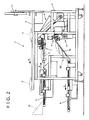
- Figs. 1 and 2 show a perspective view and a side elevation respectively, conceptually showing a strip pack apparatus 1 according to an embodiment of the present invention.
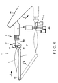
- Fig. 4 shows the flow of a series of processes, from a process of guiding a packaged item (bag X) to the interior of the strip pack apparatus 1, to a process of attaching the packaged item to a tape T.
- Figs. 3(a) and 3(b) show the packaged item (bag X) and a strip pack SP, respectively.
- Bag X has a hollow portion Y in which snacks and the like are filled, and two top and bottom seal portions Z ( Fig. 3(a) ).
- the top seal portion Z refers to the side of the seal portion Z on which the letters "SNACK" written on the bag can be read from a normal viewpoint, when one of the two seal portions Z is picked and lifted up.
- a predetermined number of bags X are aligned and attached on the tape T ( Fig. 3(b) ).
- the top seal portions Z of the bags X are attached to the tape T.
- a hole punched is provided on a portion near an end of the tape T for allowing the strip pack SP to be displayed suspended.
- the strip pack apparatus 1 having great versatility is an apparatus for manufacturing strip packs SP, and is independent from both the devices on the upstream and downstream sides. Furthermore, a packaging unit and the like for charging articles into the bags X through automatic packaging are included in the device on the upstream side. A device and the like for putting the strip packs SP into a box are included in the device on the downstream side.
- the strip pack apparatus 1 includes a body unit 2, a supply conveyor 3, a lead-in conveyor 4, a drop conveyor 5, a discharge conveyor 6, a brush unit 7, a grasp unit 8, an attaching unit 9, and a tape feeding unit 10.
- the supply conveyor 3, the lead-in conveyor 4, the drop conveyor 5, the discharge conveyor 6, the brush unit 7, the grasp unit 8, the attaching unit 9, and the tape feeding unit 10 are supported by the body unit 2.
- the supply conveyor 3 supplies the bags X produced at the device on the upstream side to the strip pack apparatus 1. More specifically, the supply conveyor 3 is arranged outside the strip pack apparatus 1, and conveys the bags X in the direction roughly horizontal, and in the direction of arrow a ( Fig. 2 ).
- the lead-in conveyor 4 guides the bags X supplied by the supply conveyor 3 to the interior of the strip pack apparatus 1. More specifically, the lead-in conveyor 4 conveys the bags X in a direction roughly horizontal, and in the direction of arrow b ( Fig. 2 ). At this time, the bags X are conveyed in the direction of arrow b with the top seal portions Z to the front. In addition, the arrow b direction is the opposite direction from the arrow a direction.
- a member 12 is arranged on the starting end portion side of the lead-in conveyor 4 that conveys the bags X in the arrow b direction ( Fig. 2 ).
- the member 12 prevents the bags X, dropped from the supply conveyor 3, from not being entered into the strip pack apparatus 1. Furthermore, the member 12 is omitted in Fig. 1 .
- the drop conveyor 5 is positioned on the terminal end portion side of the lead-in conveyor 4, and guides the bags X conveyed by the lead-in conveyor 4 to the brush unit 7.
- the drop conveyor 5 can move in the arrow e direction with a fulcrum 51 as the center thereof.
- the drop conveyor 5 tilts with the movement thereof in the arrow e direction.
- the movement of the drop conveyor 5 is linked to the movement of the grasp unit 8. This is described in detail in "C. Grasp Unit 8".
- the brush unit 7 is a device for undoing the wrinkles on the top seal portions Z of the bags X being conveyed thereto by the drop conveyor 5, and can be comprehended to be a dewrinkler. In addition, this is described in detail in "B. Brush Unit 7".
- the grasp unit 8 is a device for grasping the top seal portions Z of the bags X dewrinkled by the brush unit 7, and can be comprehended to be a grasper. In addition, this is described in detail in "C. Grasp Unit 8".
- An evacuating cylinder 70 is a device for evacuating the brush unit (dewrinkler) 7, and can be comprehended to be a dewrinkler evacuating means. In addition, this is described in detail in "D. Evacuating Cylinder 70".
- a positioning member 130 is a member for determining the position of the seal portions Z where wrinkles will be undone by the brush unit 7, and can be comprehended to be a positioning means. In addition, this is described in detail in "E. Positioning Member 130".
- the attaching unit 9 attaches the top seal portions Z of the bags X grasped by the grasp unit 8 to the tape T.
- the strip pack SP manufactured by a predetermined number of bags X being attached is being received at the tilted receiver 13, and guided to the discharge conveyor 6 ( Fig. 2 ). Note that the receiver 13 is omitted in Fig. 1 .
- Fig. 5 is a diagram of the attaching unit 9 seen from the side
- Fig. 6 is a diagram of the attaching unit 9 seen from above.
- the attaching unit 9 includes a heater 91, a clamp 92, a clamp air cylinder 93, a punch/cutter unit 94, a melting prevention member 95, and an air cylinder 96.
- the heater 91 is the source of heat used for adhering the bags X and the tape T.
- the clamp 92 capable of moving up and down, sandwiches the bags X and the tape T together with the heater 91, and is able to press the bags X against the tape T.
- the up and down movement of the clamp 92 is executed by the clamp air cylinder 93.
- the punch/cutter unit 94 can properly punch holes and put perforations on the tape T.
- the melting prevention member 95 prevents the tape T from being melted by raising the tape T up from the heater 91, with the upward movement thereof.
- the up and down movement of the melting prevention member 95 is executed by the air cylinder 96.
- the tape T and the seal portion Z are sandwiched by the downward movement of the clamp 92, and the seal portion Z is being pressed against the tape T. By doing so, the seal portion Z adheres to the tape T with the heat from the heater 91. Furthermore, the region of the seal portion Z being adhered to the tape T is shown by the symbol R in Fig. 6 .
- the attaching unit 9 repeats the adhering of the bags X, and adheres a plurality of bags X on this strip of tape T along the longitudinal direction thereof.
- the discharge conveyor 6 discharges the strip packs SP manufactured at the strip pack apparatus 1 to a device on the downstream side. More specifically, the discharge conveyor 6 conveys the strip packs SP to the arrow c direction ( Fig. 2 ).
- the tape feeding unit 10 pays out the tape T from the roll 11 in synchronism with the manufacturing of the strip pack SP.
- the roll 11 is arranged on the upper side of the body unit 2, and can be exchanged.
- strip pack apparatus 1 is independent from both the devices on the upstream and downstream sides, it may be, for example, combined with the device on the upstream side or the device on the downstream side thereof.
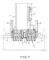
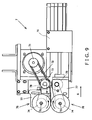
- Figs. 7 to 9 are top view, perspective view, and side view showing the brush unit (dewrinkler) 7 included in the strip pack apparatus 1 in accordance with this embodiment.
- the brush unit 7 is arranged on the distant side of the arrow b with respect to the drop conveyor 5 ( Fig. 4 ), and undoes the wrinkles on the seal portions Z of the bags X.
- the configuration of the brush unit 7 will be described below using Figs. 7 to 9 .
- the brush unit 7 includes a drive pulley 71, a timing belt 72, a driven pulley 73, a drive roller 78, and a driven roller 79, and further includes two of each of the shaft pulleys 74, rotation shafts 75, brushes 76, and supporting members 77. Note that the supporting members 77 will be described later.
- the drive pulley 71 is driven to rotate by a motor, for instance.
- the timing belt 72 is looped over the drive pulley 71 and the driven pulley 73. Consequently, the rotation of the drive pulley 71 is transferred to the driven pulley 73 through the timing belt 72.
- the drive roller 78 integral with the driven roller 73, rotates in the same direction as the direction that the driven roller 73 rotates. That is, the rotation of the drive pulley 71 is being transferred as it is through the timing belt 72 and the driven roller 73.
- the driven roller 79 is in contact with the drive roller 78, and the rotation of the drive roller 78 is being transferred directly. Furthermore, it is preferable to use metal as the material for the drive roller 78 and resin as the material for the driven roller 79, from the standpoint of efficiently transferring the power (rotation) from the drive roller 78 to the driven roller 79. It is further preferable to have the surface of the drive roller 78 knurled, as shown in Fig. 10 .
- the shaft pulleys 74 are arranged one on the upper side and one on the lower side.
- the rotation of the driven pulley 73 is transferred to the upper shaft pulley 74 via the timing belt.
- the rotation of the driven roller 79 is transferred to the lower shaft pulley 74 via the timing belt.
- the brushes 76 are arranged one on the upper side and one on the lower side, and able to sandwich the seal portions Z of bags X from the upper side and the lower side. With both the upper and the lower brushes 76, a plurality of thin disk-shaped separated brushes is arranged side by side on the rotation shafts 75 at predetermined intervals. In addition, spongious brushes, brushes like scrubbing brushes with wire rods tied together radially, and the like, can be adopted for the brushes 76.
- the upper rotation shaft 75 with the brush 76 provided couples with the upper shaft pulley 74, and rotates in the same direction as the direction that the upper shaft pulley 74 rotates.
- the lower rotation shaft 75 with the brush 76 provided couples with the lower shaft pulley 74, and rotates in the same direction as the direction that the lower shaft pulley 74 rotates.
- the upper brush 76 rotates in the same direction as the direction that the drive pulley 71 rotates, and the lower brush 76 rotates in the opposite direction from the direction that the drive pulley 71 rotates.
- the upper and lower brushes 76 can be rotated in the following manner. That is, the upper brush 76 rotates from the base portion side to the edge portion side of the seal portion Z, in the state of being in contact with the upper surface of the seal portion Z.
- the lower brush 76 rotates from the base portion side to the edge portion side of the seal portion Z, in the state of being in contact with the under surface of the seal portion Z.
- the seal portion Z can be dewrinkled efficiently and sufficiently, since the wrinkles are undone by the seal portion Z being sandwiched from above and below.
- the brushes 76 can be comprehended to be the dewrinkling members, in view of the dewrinkling being done by the brushes 76.
- the supporting members 77 are arranged one on the upper side and one on the lower side ( Fig. 9 ).
- the upper supporting member 77 supports the driven pulley 73, the drive roller 78, the upper shaft pulley 74, the upper rotation shaft 75, and the upper brush 76.
- the lower supporting member 77 supports the driven roller 79, the lower shaft pulley 74, the lower rotation shaft 75, and the lower brush 76.
- Both the upper and the lower supporting members 77 are positioned in the center of the brushes 76 in the width direction of the brushes 76 ( Figs. 7 and 8 ). For this reason, different from if the supporting members 77 are provided lateral to the brushes 76, the supporting members 77 will not interfere with a grip fingers 81 of the grasp unit 8 to be described later even if the grip fingers 81 come near the brushes 76. This is because the supporting members 77 do not stick out from the region on which the wrinkles are undone by the brushes 76. Consequently, the seal portions Z of the bags X can be grasped at a position near the brushes 76.
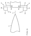
- Fig. 11 is a diagram of the grasp unit (grasper) 8 viewed from the side.
- Figs. 12(a) to 12(c) show the operation of the grasp unit 8 in sequence.
- the configuration and operation of the grasp unit 8, and the positional relationship thereof with the brush unit 7 will be described below using Figs. 11 , 12 , and 4 .
- the control of the grasp unit 8 will be described later.
- the grasp unit 8 grasps the upper seal portions Z of the bags X dewrinkled by the brush unit 7 from the upper seal portions Z side (distant side of arrow b) with respect to the bags X. More specifically, the grasp unit 8 is arranged on the distant side of the arrow b from the drop conveyor 5, and includes the pair of grip fingers 81, hands 82, arms 83, and guide rails 84 ( Fig. 4 ).
- the pair of grip fingers 81 is arranged one on the upper side and the other on the lower side, and can grasp the seal portions Z by sandwiching the seal portions Z from above and below.
- This pair of grip fingers 81 each includes a finger body 81 a and a grasp portion 81b.
- the finger bodies 81a can move (pivot) in the arrow f direction ( Fig. 11 ), with fulcrums 82a provided on the hand 82 as the centers thereof.
- the grasp portions 81 b are mounted on the tip of the finger bodies 81 a, and the surfaces 81b1 for grasping the seal portions Z take on a curved shape. Rubber and the like, for instance, having elasticity, is adopted for the grasp portions 81 b. By doing so, it becomes easier to grasp the seal portions Z, and as a result, it can prevent the seal portions Z from falling off from between the upper and lower grasp portions 81 b after being grasped.
- the hands 82 are supported on the arms 83, and are both equipped with the pair of grip fingers 81 ( Fig. 4 ).
- the hands 82 can adjust the positions thereof relative to the arms 83.
- the arms 83 can move along the tiled guide rails 84.
- each of the grip fingers 81, and the hands 82 are on the both sides of the brush unit 7 .
- the grip fingers 81 On the both sides of the brush unit 7 are each of the grip fingers 81, and the hands 82 as well, for these grip fingers 81 ( Fig. 7 ).
- the grip fingers 81 grasps the seal portions Z longitudinally at the both sides of the brushes 76. Consequently, wrinkles on the portion of the seal portions Z between the two grip fingers 81 are undone by the brush unit 7.
- the grasp unit 8 holds the seal portions Z after the seal portions Z have been dewrinkled by the brush unit 7 at a position (grasp position) P1 near the terminal end portion of the drop conveyor 5. Details will be described using Figs. 12 and 4 .
- Fig. 12 shows the seal portion Z, from a state of starting to be grasped ( Fig. 12(a) ), to a state of completely being grasped ( Fig. 12(c) ). More specifically, since the surfaces 81b1 of the grasp portions 81b take on a curved shape, the seal portion Z is grasped gradually from the edge portion side to the base portion side. By doing so, it is possible to prevent the seal portion Z from being wrinkled when the grasp unit 8 grasps the seal portion Z.
- the grasp unit 8 moves in the arrow d ( Fig. 4 ) direction, more specifically, distant side (front side) of arrow b ( Fig. 4 ), and to the direction slanting downwards.
- the bag X being grasped moves to the attaching unit 9, more specifically, to a position (attaching position) P2. This is for separating the grasp position P1 and the attaching position P2. By doing so, there is plenty of space for the attachment operation at the attaching position P2. Consequently, the attachment operation can be done easily, and as a result, a favorable state of attachment can be obtained easily.
- the drop conveyor 5 moves to the arrow e ( Fig. 4 ) direction, and tilts.
- the grasp unit 8 described above does not hold the side portion of the bag X, but holds the seal portion Z from the side of the seal portion Z of the bag X, where it is to be attached to the tape T ( Figs. 11 and 12 ). Consequently, regardless of the dimension of the width of the seal portion Z, the grasp unit 8 is able to grasp the seal portion Z of the bag X precisely.
- the seal portions Z of the bags X can be flattened even if the seal portions Z are bent, and as a result, bags X can be attached to the tape T in a favorable state.
- the grasp unit 8 holds the seal portion Z at the both sides of the attachment region R provided on the seal portion Z ( Fig. 6 ), the attachment region R of the seal portion Z to be attached to the tape T can be flattened efficiently. Consequently, this further enhances the attachment of the bags X.
- the grasp unit 8 holds the seal portion Z at the both sides of the brush unit (dewrinkler) 7 for undoing the wrinkles on the seal portion Z ( Fig. 7 ), the region of the seal portion Z on which wrinkles are undone by the brush unit 7 can be flattened efficiently. Consequently, this further enhances the attachment of the items X.
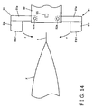
- Figs. 13 and 14 show the strip pack apparatus 1 having the above described grasp unit 8.
- This strip pack apparatus 1 further includes a bag position detection sensor 110 and a grip detection sensor 120.
- the bag position detection sensor 110 is arranged on the terminal end portion of the drop conveyor 5 ( Fig. 13 ), and detects whether or not a bag X is in the proper position on the drop conveyor 5 before the bag X is held by the grasp unit 8. Something that analyzes an image of an object on the drop conveyor 5 taken by a CCD camera and the like, for instance, can be adopted for this bag position detection sensor 110.
- the grip detection sensor 120 is arranged on the hand 82 ( Fig. 14 ), and detects when the seal portion Z of the bag X is held by the pair of grip fingers 81. Something that analyzes whether or not an object is being sandwiched between the grip fingers 81 by calculating the distance and the included angle between the grip fingers 81 when the pair of grip fingers 81 is closed, for instance, can be adopted for the grip detection sensor 120.
- Fig. 15 is a block diagram showing the connection relationship between a control unit 100 of the strip pack apparatus 1 and each of the devices.
- Fig. 16 is a flowchart showing the control of the strip pack apparatus 1.
- the control unit 100 of the strip pack apparatus 1 is connected to each of the conveyors 4 to 6, each of the units 7 to 10, and each of the sensors 110 and 120, and is able to receive and send various signals.
- the control of the strip pack apparatus 1 through the control unit 100 will be described below using Fig. 16 .
- a bag X is guided in by the lead-in conveyor 4 to the grasp position P1 (Step S101), and dewrinkling of the seal portion Z is performed on this bag X by the brush unit 7 (Step S102). Then, the bag position detection sensor 110 judges whether or not the bag X is in an acceptable position (Step S103). When it is judged that the position is acceptable, the grasp unit 8 holds the bag X (Step S 104). On the other hand, if it is judged that the position is unacceptable, the grasp unit 8 is prevented from holding the bag X (Step S113).
- Step S104 the grip detection sensor 120 judges whether or not the bag X is being held properly (Step S105). When it is judged that the bag X is being held properly, the bag X is moved slanting downward on the front side of the conveying direction b (Step S 106). On the other hand, if it is judged that the bag X is not being held properly, the bag X is prevented from being moved (Step S115).
- Step S107 the bag X is attached to the tape T by the attaching unit 9 (Step S107). Then, tape T is sent out by the tape feeding unit 10, and the strip pack SP, being the product, is discharged (Step S108).
- Step S103 in Fig. 16 whether or not the position of the item X is proper is detected by the bag position detection sensor 110 before it is being held by the grasp unit 8 (Step S103 in Fig. 16 ), and whether or not the item X judged to be in a proper position is held properly by the grasp unit 8 is detected (Step S105 in Fig. 16 ). Consequently, the bag X is attached to the tape T only when it is judged to be proper in both the detections, and thus, a plurality of bags X can be lined up visually pleasantly on the tape T. As a result, the likeliness of a strip pack SP (refer to Fig. 3(b) ) being a non-defective product can be improved.
- the seal portion Z of a bag X may be held from the sides by the pair of grip fingers 81 shown in chained line in Figs. 6 and 7 . By doing so, portions near the portion dewrinkled by the brush unit 7 can be held, and also, the seal portion Z being held will not slip off easily from the pair of grip fingers 81.
- extension portions 81x extending to the rear side in the conveying direction b from the pair of grip fingers 81 may be provided.
- portions of the hollow portion Y can also be held. Consequently, even if the contents filled inside the hollow portion Y moves to the side of the seal portion Z due to inertia and the like, the seal portion Z can be prevented from being looped back or bent, due to a pressure and the like occurred when moving.
- extension portions 81y extending in the width direction from the pair of grip fingers 81 may be provided. By doing so, a wide range of the seal portion Z can be held, and as a result, the seal portion Z being held will not slip off easily from the pair of grip fingers 81.
- the pair of grip fingers 81 can get closer to the attachment region R.
- the evacuating cylinder 70 ( Fig. 9 ) has a rod, and this rod can be reciprocated along the arrow g direction.
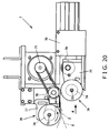
- the rod is coupled with the lower supporting member 77 of the brush unit 7. The operation of the evacuating cylinder 70 will be described below using Fig. 20 .
- the evacuating cylinder 70 moves the supporting member 77 coupled with the rod in the arrow g direction. That is, the lower supporting member 77 is evacuated to the arrow g direction. By doing so, the brush 76 supported on the lower supporting member 77 is also evacuated to the arrow g direction, that is, to the front side of the conveying direction b.
- the bag X held by the grasp unit 8 can be moved smoothly from the grasp position P1 to the attaching position P2. That is, it is possible to prevent the bag X from interfering with the brush unit 7.
- the driven roller 79 supported on the lower supporting member 77 is also evacuated to the arrow g direction, the driven roller 79 separates from the drive roller 78 ( Fig. 20 ), and as a result, the rotation of the lower brush 76 stops. Consequently, when the bag X held by the grasp unit 8 moves to the arrow d direction, even if the bag X is touched by the lower brush 76, since the brush 76 is stopped, it is possible to prevent the dewrinkled seal portion Z from being wrinkled again.
- Fig. 21 is a flowchart showing the control of the strip pack apparatus 1 having the evacuating cylinder 70.
- the evacuating cylinder 70 is connected to the control unit 100 shown in Fig. 15 .
- the bag X is guided in by the lead-in conveyor 4 to the grasp position P1 (Step S101), and the seal portion Z of the bag X is dewrinkled by the brush unit 7 (Step S 102). Then, the bag is held by the grasp unit 8 (Step S 103). After that, the bag X is moved slanting downward on the front side of the conveying direction b (Step S104). At this time, the lower brush 76 of the brush unit 7 is evacuated to the front side of the conveying direction b by the evacuating cylinder 70 (Step S105).
- the bag X When the bag X reaches the attaching position P2, the bag X is attached to the tape T by the attaching unit 9 (Step S106). The tape T is then paid out by the tape feeding unit 10, and the strip pack SP, being the product, is discharged (Step S107).
- Fig. 22 shows a modification example of the brush unit 7. With the brush unit 7 shown in Fig. 15 , the lower brush 76 can turn in the arrow h direction (downward).
- the lower brush 76 can be evacuated to the front side of the conveying direction b by turning the lower brush 76 in the arrow h direction.
- the configuration of the brush unit 7 will not become complicated.
- Figs. 23 to 25 show the strip pack apparatus 1 having the positioning member 130. In addition, in all the figures, the area around the brush unit 7 is shown enlarged.
- the positioning member 130 is a member that takes on a comb-like shape, and is supported on the lower supporting member 77.
- the rod of the evacuating cylinder 70 is moved to the opposite direction from the arrow g direction, and when the drive roller 78 and the driven roller 79 are in the state of being in contact with each other ( Fig. 24 ), the positioning member 130 meshes with the brushes 76. More specifically, the comb portion of the positioning member 130 is positioned between the plurality of the separated brushes that make up the brushes 76.
- the positioning member 130 since the positioning member 130 is supported on the lower supporting member 77, by evacuating the supporting member 77 to the arrow g direction through the evacuating cylinder 70, the positioning member 130 can also be evacuated to the arrow g direction ( Fig. 25 ). Consequently, the bag X held by the grasp unit 8 can be moved smoothly from the grasp position P1 to the attaching position P2. That is, it is possible to prevent the bag X from interfering with the positioning member 130. In addition, the evacuation of the positioning member 130 is performed in Step S105 shown in Fig. 21 .
- the positioning member 130 since the positioning member 130 is supported on the lower supporting member 77, same as the brush 76, although it can be evacuated to the arrow g direction through the same evacuating cylinder 70, for example, the positioning member 130 may be evacuated in the arrow g direction by a different cylinder from the evacuating cylinder 70. However, as shown in Figs. 23 to 25 , it is more efficient to evacuate both the positioning member 130 and the brush 76 by the same evacuating cylinder 70.
Landscapes
- Engineering & Computer Science (AREA)
- Mechanical Engineering (AREA)
- Containers And Plastic Fillers For Packaging (AREA)
- Auxiliary Devices For And Details Of Packaging Control (AREA)
- Basic Packing Technique (AREA)
Claims (10)
- Appareil de conditionnement en chapelet destiné à manipuler un article à des fins d'attache sur une feuille de doublage au niveau d'une partie d'extrémité de l'article, l'appareil comportant :un dispositif de saisie (8) adapté pour saisir la partie d'extrémité ; caractérisé parun dispositif de dépliement (7) destiné à déplier des plis sur la partie d'extrémité de l'article saisi par le dispositif de saisie (8) dans lequelle dispositif de saisie (8) est adapté pour saisir la même partie d'extrémité que la partie d'extrémité sur laquelle des plis sont dépliés par le dispositif de dépliement, etle dispositif de dépliement (7) comprend un élément de dépliement (76) pour déplier les plis sur la partie d'extrémité, et un élément de support destiné à supporter l'élément de dépliement au niveau d'une partie intermédiaire de cet élément de dépliement.
- Appareil de conditionnement en chapelet selon la revendication 1, dans lequel
l'élément de dépliement (76) est adapté pour être arrangé sur les deux surfaces de la partie d'extrémité. - Appareil de conditionnement en chapelet selon la revendication 1, comportant par ailleurs :un moyen de transport (4) destiné à transporter un article approximativement dans la direction horizontale ;un moyen de déplacement destiné à déplacer l'article, la partie d'extrémité étant dépliée par le dispositif de dépliement, allant en s'inclinant vers le bas sur le côté avant dans la direction de transport ;un moyen d'attache (9) destiné à attacher l'article déplacé par ce moyen de déplacement jusque sur une feuille de doublage au niveau de la partie d'extrémité ; etun moyen d'évacuation de dépliement (70) destiné à évacuer le moyen de dépliement jusque sur le côté avant dans la direction de transport quand l'article est déplacé par le moyen de déplacement,dans lequel le dispositif de dépliement (7) est adapté pour déplier des plis sur la partie d'extrémité sur le côté avant dans la direction de transport de l'article transporté par ce moyen de transport.
- Appareil de conditionnement en chapelet selon la revendication 3, dans lequel
le dispositif de dépliement (7) comprend un élément de dépliement supérieur (76) positionné au-dessus de la partie d'extrémité pour déplier des plis sur une surface supérieure de la partie d'extrémité, et un élément de dépliement inférieur (76) positionné sous la partie d'extrémité pour déplier des plis sur une surface inférieure de la partie d'extrémité, et
le moyen d'évacuation de dépliement (70) évacue uniquement l'élément de dépliement inférieur. - Appareil de conditionnement en chapelet selon la revendication 4, dans lequel
le moyen d'évacuation de dépliement (70) déplace l'élément de dépliement inférieur (76) approximativement à l'horizontale, de manière à évacuer l'élément de dépliement inférieur sur le côté avant dans la direction de transport. - Appareil de conditionnement en chapelet selon la revendication 4, dans lequel
le moyen d'évacuation de dépliement (70) tourne l'élément de dépliement inférieur (76) vers le bas, de manière à évacuer l'élément de dépliement inférieur sur le côté avant dans la direction de transport. - Appareil de conditionnement en chapelet selon la revendication 5, dans lequel
l'élément de dépliement supérieur (76) et l'élément de dépliement inférieur (76) sont une brosse supérieure et une brosse inférieure destinées à tourner depuis un côté de partie de base jusqu'à un côté de partie de bord, dans l'état de mise en contact avec la surface supérieure et la surface inférieure de la partie d'extrémité,
un rouleau d'entraînement entraîné par une source d'entraînement à des fins de rotation de la brosse supérieure, et un rouleau entraîné entraîné par la mise en contact avec ce rouleau d'entraînement à des fins de rotation de la brosse inférieure sont inclus, et
quand la brosse inférieure est déplacée approximativement à l'horizontale par le moyen d'évacuation de dépliement (70), le rouleau entraîné est configuré pour se séparer du rouleau d'entraînement. - Appareil de conditionnement en chapelet selon la revendication 1, comportant par ailleurs :un moyen de transport (4) destiné à transporter un article approximativement dans la direction horizontale ;un moyen de positionnement destiné à positionner l'article par mise en contact avec la partie d'extrémité sur le côté avant dans la direction de transport de l'article transporté par ce moyen de transport ;un moyen de déplacement destiné à déplacer l'article positionné par ce moyen de positionnement allant en s'inclinant vers le bas sur le côté avant dans la direction de transport ;un moyen d'attache (9) destiné à attacher l'article déplacé par ce moyen de déplacement jusque sur une feuille de doublage au niveau de la partie d'extrémité ; etun moyen d'évacuation de positionnement (70) destiné à évacuer le moyen de positionnement jusque sur le côté avant dans la direction de transport quand l'article est déplacé par le moyen de déplacement.
- Appareil de conditionnement en chapelet selon la revendication 8, comportant :un moyen d'évacuation de dépliement (70) destiné à évacuer le moyen de dépliement jusque sur le côté avant dans la direction de transport quand l'article est déplacé par le moyen de déplacement,dans lequel le dispositif de dépliement (7) est adapté pour déplier des plis sur la partie d'extrémité sur le côté avant dans la direction de transport de l'article positionné par ce moyen de positionnement.
- Appareil de conditionnement en chapelet selon la revendication 9, dans lequel
le dispositif de dépliement (7) comprend un élément de dépliement supérieur (76) positionné au-dessus de la partie d'extrémité pour déplier des plis sur une surface supérieure de la partie d'extrémité, et un élément de dépliement inférieur (76) positionné sous la partie d'extrémité pour déplier des plis sur une surface inférieure de la partie d'extrémité,
le moyen d'évacuation de dépliement (70) évacue uniquement l'élément de dépliement inférieur,
le moyen de positionnement est inclus dans l'élément de dépliement inférieur, et
le moyen d'évacuation de positionnement est le moyen d'évacuation de dépliement (70).
Priority Applications (1)
| Application Number | Priority Date | Filing Date | Title |
|---|---|---|---|
| EP12166534A EP2489598A1 (fr) | 2006-10-25 | 2007-10-03 | Appareil de conditionnement en chapelet, dispositif de préhension et dispositif de dépliement destiné à être utilisé dans l'appareil |
Applications Claiming Priority (5)
| Application Number | Priority Date | Filing Date | Title |
|---|---|---|---|
| JP2006289940A JP4994785B2 (ja) | 2006-10-25 | 2006-10-25 | ストリップパック装置 |
| JP2006289938A JP4994783B2 (ja) | 2006-10-25 | 2006-10-25 | ストリップパック装置に用いる皺伸ばし装置及びそれを用いたストリップパック装置 |
| JP2006289939A JP4994784B2 (ja) | 2006-10-25 | 2006-10-25 | ストリップパック装置 |
| JP2006289936A JP5059375B2 (ja) | 2006-10-25 | 2006-10-25 | ストリップパック装置 |
| PCT/JP2007/069385 WO2008050592A1 (fr) | 2006-10-25 | 2007-10-03 | Appareil de conditionnement en chapelet, et dispositif de préhension et dispositif de dépliement destiné à être utilisé dans l'appareil |
Related Child Applications (2)
| Application Number | Title | Priority Date | Filing Date |
|---|---|---|---|
| EP12166534A Division EP2489598A1 (fr) | 2006-10-25 | 2007-10-03 | Appareil de conditionnement en chapelet, dispositif de préhension et dispositif de dépliement destiné à être utilisé dans l'appareil |
| EP12166534.3 Division-Into | 2012-05-03 |
Publications (3)
| Publication Number | Publication Date |
|---|---|
| EP2088082A1 EP2088082A1 (fr) | 2009-08-12 |
| EP2088082A4 EP2088082A4 (fr) | 2011-11-16 |
| EP2088082B1 true EP2088082B1 (fr) | 2012-12-05 |
Family
ID=39324398
Family Applications (2)
| Application Number | Title | Priority Date | Filing Date |
|---|---|---|---|
| EP12166534A Withdrawn EP2489598A1 (fr) | 2006-10-25 | 2007-10-03 | Appareil de conditionnement en chapelet, dispositif de préhension et dispositif de dépliement destiné à être utilisé dans l'appareil |
| EP07829124A Not-in-force EP2088082B1 (fr) | 2006-10-25 | 2007-10-03 | Appareil de conditionnement en chapelet, et dispositif de préhension et dispositif de dépliement destiné à être utilisé dans l'appareil |
Family Applications Before (1)
| Application Number | Title | Priority Date | Filing Date |
|---|---|---|---|
| EP12166534A Withdrawn EP2489598A1 (fr) | 2006-10-25 | 2007-10-03 | Appareil de conditionnement en chapelet, dispositif de préhension et dispositif de dépliement destiné à être utilisé dans l'appareil |
Country Status (5)
| Country | Link |
|---|---|
| US (1) | US20100083475A1 (fr) |
| EP (2) | EP2489598A1 (fr) |
| AU (1) | AU2007310276B2 (fr) |
| BR (1) | BRPI0718024A2 (fr) |
| WO (1) | WO2008050592A1 (fr) |
Families Citing this family (3)
| Publication number | Priority date | Publication date | Assignee | Title |
|---|---|---|---|---|
| JP2009102034A (ja) | 2007-10-23 | 2009-05-14 | Ishida Co Ltd | ストリップパック装置 |
| US9415889B2 (en) | 2011-09-23 | 2016-08-16 | Premier Tech Technologies Ltee | Fully automated bag preparing system for various types of bags |
| JP2015168456A (ja) * | 2014-03-06 | 2015-09-28 | 東洋自動機株式会社 | 袋の供給方法及び袋供給装置 |
Family Cites Families (14)
| Publication number | Priority date | Publication date | Assignee | Title |
|---|---|---|---|---|
| US3864895A (en) | 1973-02-26 | 1975-02-11 | Wright Machinery Company Inc | Multi-pack method and apparatus |
| JPS60154206U (ja) * | 1984-03-27 | 1985-10-15 | オリヒロ株式会社 | 横シ−ルしわ防止装置 |
| US4829745A (en) * | 1987-12-07 | 1989-05-16 | The Dow Chemical Company | Tube spreader for removing wrinkles in tube stock |
| DE3938410A1 (de) * | 1989-11-18 | 1991-05-23 | Focke & Co | Vorrichtung zum anbringen eines klebestreifens an einem faltkarton oder dergleichen |
| US5048270A (en) * | 1990-01-26 | 1991-09-17 | Zip-Pak Incorporated | Wrinkle free film spreader device for form, fill and seal machines |
| US5433060A (en) * | 1994-02-10 | 1995-07-18 | Recot, Inc. | Automated method and apparatus for detachably securing flexible packages to a display strip |
| JPH1111442A (ja) * | 1997-06-20 | 1999-01-19 | Ishida Co Ltd | 包装装置 |
| US6860958B2 (en) * | 2002-06-27 | 2005-03-01 | Cryovac, Inc. | Wrinkle reduction assembly |
| CA2445607A1 (fr) * | 2002-10-18 | 2004-04-18 | Boss Packaging Inc. | Dispositif de presentation de sacs pour machine d'emballage |
| JP2004182302A (ja) | 2002-12-04 | 2004-07-02 | Ishida Co Ltd | 帯体取付装置および製袋包装機 |
| US7293591B2 (en) * | 2003-02-28 | 2007-11-13 | Ishida Co., Ltd. | System for mounting products to a tape |
| JP3602527B1 (ja) * | 2003-06-19 | 2004-12-15 | 株式会社イシダ | ストリップバッグ装置 |
| JP4619648B2 (ja) * | 2003-12-03 | 2011-01-26 | 株式会社イシダ | ストリップバッグ装置 |
| US7386968B2 (en) * | 2005-03-30 | 2008-06-17 | Sealed Air Corporation | Packaging machine and method |
-
2007
- 2007-10-03 EP EP12166534A patent/EP2489598A1/fr not_active Withdrawn
- 2007-10-03 BR BRPI0718024-1A patent/BRPI0718024A2/pt not_active IP Right Cessation
- 2007-10-03 EP EP07829124A patent/EP2088082B1/fr not_active Not-in-force
- 2007-10-03 US US12/447,124 patent/US20100083475A1/en not_active Abandoned
- 2007-10-03 AU AU2007310276A patent/AU2007310276B2/en not_active Ceased
- 2007-10-03 WO PCT/JP2007/069385 patent/WO2008050592A1/fr not_active Ceased
Also Published As
| Publication number | Publication date |
|---|---|
| EP2088082A1 (fr) | 2009-08-12 |
| US20100083475A1 (en) | 2010-04-08 |
| WO2008050592A1 (fr) | 2008-05-02 |
| AU2007310276A1 (en) | 2008-05-02 |
| BRPI0718024A2 (pt) | 2013-11-12 |
| EP2489598A1 (fr) | 2012-08-22 |
| AU2007310276B2 (en) | 2013-03-28 |
| EP2088082A4 (fr) | 2011-11-16 |
Similar Documents
| Publication | Publication Date | Title |
|---|---|---|
| JP4153240B2 (ja) | 個体物品を筒状袋体包装ステーションに供給する装置ならびに方法 | |
| JP2002037206A (ja) | 縦型製袋包装機 | |
| JP7080538B2 (ja) | 帯掛け包装装置 | |
| EP2088082B1 (fr) | Appareil de conditionnement en chapelet, et dispositif de préhension et dispositif de dépliement destiné à être utilisé dans l'appareil | |
| US11046467B2 (en) | Packaging apparatus | |
| US20170081068A1 (en) | Packaging apparatus | |
| US8047249B2 (en) | Strip pack apparatus | |
| CN101528548B (zh) | 揭取式包装装置以及用于该装置的夹持装置 | |
| JP2000255759A (ja) | 物品の排出装置 | |
| JP4907223B2 (ja) | ストリップパック装置 | |
| JP3833590B2 (ja) | 袋搬送装置 | |
| JP4762116B2 (ja) | シート供給装置 | |
| JP4478924B2 (ja) | 包装袋への小袋の貼着装置及びその貼着方法 | |
| JP3805542B2 (ja) | カードの繰出し装置及び繰出し方法 | |
| JP4704183B2 (ja) | ストリップバッグ装置 | |
| JP4475129B2 (ja) | シート状物品の取り出し装置 | |
| JP3830437B2 (ja) | 製袋包装機 | |
| JP2004181913A (ja) | 袋掛け装置 | |
| JP3173843U (ja) | 包装装置 | |
| JP4994784B2 (ja) | ストリップパック装置 | |
| TWI572531B (zh) | The method of tearing the label and affixing the label to the magazine | |
| JP2022018398A (ja) | 袋処理システム | |
| JP2005170472A (ja) | ストリップバッグ装置 | |
| JPH1149108A (ja) | ストレッチ包装機 |
Legal Events
| Date | Code | Title | Description |
|---|---|---|---|
| PUAI | Public reference made under article 153(3) epc to a published international application that has entered the european phase |
Free format text: ORIGINAL CODE: 0009012 |
|
| 17P | Request for examination filed |
Effective date: 20090522 |
|
| AK | Designated contracting states |
Kind code of ref document: A1 Designated state(s): AT BE BG CH CY CZ DE DK EE ES FI FR GB GR HU IE IS IT LI LT LU LV MC MT NL PL PT RO SE SI SK TR |
|
| DAX | Request for extension of the european patent (deleted) | ||
| A4 | Supplementary search report drawn up and despatched |
Effective date: 20111018 |
|
| RIC1 | Information provided on ipc code assigned before grant |
Ipc: B65B 15/04 20060101AFI20111011BHEP |
|
| GRAP | Despatch of communication of intention to grant a patent |
Free format text: ORIGINAL CODE: EPIDOSNIGR1 |
|
| GRAS | Grant fee paid |
Free format text: ORIGINAL CODE: EPIDOSNIGR3 |
|
| GRAA | (expected) grant |
Free format text: ORIGINAL CODE: 0009210 |
|
| AK | Designated contracting states |
Kind code of ref document: B1 Designated state(s): AT BE BG CH CY CZ DE DK EE ES FI FR GB GR HU IE IS IT LI LT LU LV MC MT NL PL PT RO SE SI SK TR |
|
| REG | Reference to a national code |
Ref country code: GB Ref legal event code: FG4D |
|
| REG | Reference to a national code |
Ref country code: CH Ref legal event code: EP |
|
| REG | Reference to a national code |
Ref country code: AT Ref legal event code: REF Ref document number: 587126 Country of ref document: AT Kind code of ref document: T Effective date: 20121215 |
|
| REG | Reference to a national code |
Ref country code: IE Ref legal event code: FG4D |
|
| REG | Reference to a national code |
Ref country code: DE Ref legal event code: R096 Ref document number: 602007027202 Country of ref document: DE Effective date: 20130131 |
|
| REG | Reference to a national code |
Ref country code: AT Ref legal event code: MK05 Ref document number: 587126 Country of ref document: AT Kind code of ref document: T Effective date: 20121205 |
|
| PG25 | Lapsed in a contracting state [announced via postgrant information from national office to epo] |
Ref country code: FI Free format text: LAPSE BECAUSE OF FAILURE TO SUBMIT A TRANSLATION OF THE DESCRIPTION OR TO PAY THE FEE WITHIN THE PRESCRIBED TIME-LIMIT Effective date: 20121205 Ref country code: SE Free format text: LAPSE BECAUSE OF FAILURE TO SUBMIT A TRANSLATION OF THE DESCRIPTION OR TO PAY THE FEE WITHIN THE PRESCRIBED TIME-LIMIT Effective date: 20121205 Ref country code: LT Free format text: LAPSE BECAUSE OF FAILURE TO SUBMIT A TRANSLATION OF THE DESCRIPTION OR TO PAY THE FEE WITHIN THE PRESCRIBED TIME-LIMIT Effective date: 20121205 Ref country code: ES Free format text: LAPSE BECAUSE OF FAILURE TO SUBMIT A TRANSLATION OF THE DESCRIPTION OR TO PAY THE FEE WITHIN THE PRESCRIBED TIME-LIMIT Effective date: 20130316 |
|
| REG | Reference to a national code |
Ref country code: NL Ref legal event code: VDEP Effective date: 20121205 |
|
| REG | Reference to a national code |
Ref country code: LT Ref legal event code: MG4D |
|
| PG25 | Lapsed in a contracting state [announced via postgrant information from national office to epo] |
Ref country code: CY Free format text: LAPSE BECAUSE OF FAILURE TO SUBMIT A TRANSLATION OF THE DESCRIPTION OR TO PAY THE FEE WITHIN THE PRESCRIBED TIME-LIMIT Effective date: 20121205 Ref country code: GR Free format text: LAPSE BECAUSE OF FAILURE TO SUBMIT A TRANSLATION OF THE DESCRIPTION OR TO PAY THE FEE WITHIN THE PRESCRIBED TIME-LIMIT Effective date: 20130306 Ref country code: SI Free format text: LAPSE BECAUSE OF FAILURE TO SUBMIT A TRANSLATION OF THE DESCRIPTION OR TO PAY THE FEE WITHIN THE PRESCRIBED TIME-LIMIT Effective date: 20121205 Ref country code: PL Free format text: LAPSE BECAUSE OF FAILURE TO SUBMIT A TRANSLATION OF THE DESCRIPTION OR TO PAY THE FEE WITHIN THE PRESCRIBED TIME-LIMIT Effective date: 20121205 Ref country code: LV Free format text: LAPSE BECAUSE OF FAILURE TO SUBMIT A TRANSLATION OF THE DESCRIPTION OR TO PAY THE FEE WITHIN THE PRESCRIBED TIME-LIMIT Effective date: 20121205 |
|
| PG25 | Lapsed in a contracting state [announced via postgrant information from national office to epo] |
Ref country code: AT Free format text: LAPSE BECAUSE OF FAILURE TO SUBMIT A TRANSLATION OF THE DESCRIPTION OR TO PAY THE FEE WITHIN THE PRESCRIBED TIME-LIMIT Effective date: 20121205 |
|
| PG25 | Lapsed in a contracting state [announced via postgrant information from national office to epo] |
Ref country code: EE Free format text: LAPSE BECAUSE OF FAILURE TO SUBMIT A TRANSLATION OF THE DESCRIPTION OR TO PAY THE FEE WITHIN THE PRESCRIBED TIME-LIMIT Effective date: 20121205 Ref country code: SK Free format text: LAPSE BECAUSE OF FAILURE TO SUBMIT A TRANSLATION OF THE DESCRIPTION OR TO PAY THE FEE WITHIN THE PRESCRIBED TIME-LIMIT Effective date: 20121205 Ref country code: BG Free format text: LAPSE BECAUSE OF FAILURE TO SUBMIT A TRANSLATION OF THE DESCRIPTION OR TO PAY THE FEE WITHIN THE PRESCRIBED TIME-LIMIT Effective date: 20130305 Ref country code: BE Free format text: LAPSE BECAUSE OF FAILURE TO SUBMIT A TRANSLATION OF THE DESCRIPTION OR TO PAY THE FEE WITHIN THE PRESCRIBED TIME-LIMIT Effective date: 20121205 Ref country code: CZ Free format text: LAPSE BECAUSE OF FAILURE TO SUBMIT A TRANSLATION OF THE DESCRIPTION OR TO PAY THE FEE WITHIN THE PRESCRIBED TIME-LIMIT Effective date: 20121205 Ref country code: IS Free format text: LAPSE BECAUSE OF FAILURE TO SUBMIT A TRANSLATION OF THE DESCRIPTION OR TO PAY THE FEE WITHIN THE PRESCRIBED TIME-LIMIT Effective date: 20130405 |
|
| PG25 | Lapsed in a contracting state [announced via postgrant information from national office to epo] |
Ref country code: PT Free format text: LAPSE BECAUSE OF FAILURE TO SUBMIT A TRANSLATION OF THE DESCRIPTION OR TO PAY THE FEE WITHIN THE PRESCRIBED TIME-LIMIT Effective date: 20130405 Ref country code: RO Free format text: LAPSE BECAUSE OF FAILURE TO SUBMIT A TRANSLATION OF THE DESCRIPTION OR TO PAY THE FEE WITHIN THE PRESCRIBED TIME-LIMIT Effective date: 20121205 Ref country code: NL Free format text: LAPSE BECAUSE OF FAILURE TO SUBMIT A TRANSLATION OF THE DESCRIPTION OR TO PAY THE FEE WITHIN THE PRESCRIBED TIME-LIMIT Effective date: 20121205 |
|
| PLBE | No opposition filed within time limit |
Free format text: ORIGINAL CODE: 0009261 |
|
| STAA | Information on the status of an ep patent application or granted ep patent |
Free format text: STATUS: NO OPPOSITION FILED WITHIN TIME LIMIT |
|
| PG25 | Lapsed in a contracting state [announced via postgrant information from national office to epo] |
Ref country code: DK Free format text: LAPSE BECAUSE OF FAILURE TO SUBMIT A TRANSLATION OF THE DESCRIPTION OR TO PAY THE FEE WITHIN THE PRESCRIBED TIME-LIMIT Effective date: 20121205 |
|
| 26N | No opposition filed |
Effective date: 20130906 |
|
| REG | Reference to a national code |
Ref country code: DE Ref legal event code: R097 Ref document number: 602007027202 Country of ref document: DE Effective date: 20130906 |
|
| PG25 | Lapsed in a contracting state [announced via postgrant information from national office to epo] |
Ref country code: MC Free format text: LAPSE BECAUSE OF FAILURE TO SUBMIT A TRANSLATION OF THE DESCRIPTION OR TO PAY THE FEE WITHIN THE PRESCRIBED TIME-LIMIT Effective date: 20121205 |
|
| REG | Reference to a national code |
Ref country code: CH Ref legal event code: PL |
|
| GBPC | Gb: european patent ceased through non-payment of renewal fee |
Effective date: 20131003 |
|
| REG | Reference to a national code |
Ref country code: IE Ref legal event code: MM4A |
|
| PG25 | Lapsed in a contracting state [announced via postgrant information from national office to epo] |
Ref country code: GB Free format text: LAPSE BECAUSE OF NON-PAYMENT OF DUE FEES Effective date: 20131003 Ref country code: CH Free format text: LAPSE BECAUSE OF NON-PAYMENT OF DUE FEES Effective date: 20131031 Ref country code: LI Free format text: LAPSE BECAUSE OF NON-PAYMENT OF DUE FEES Effective date: 20131031 |
|
| REG | Reference to a national code |
Ref country code: FR Ref legal event code: ST Effective date: 20140630 |
|
| REG | Reference to a national code |
Ref country code: DE Ref legal event code: R119 Ref document number: 602007027202 Country of ref document: DE Effective date: 20140501 |
|
| PG25 | Lapsed in a contracting state [announced via postgrant information from national office to epo] |
Ref country code: DE Free format text: LAPSE BECAUSE OF NON-PAYMENT OF DUE FEES Effective date: 20140501 Ref country code: IT Free format text: LAPSE BECAUSE OF NON-PAYMENT OF DUE FEES Effective date: 20131003 Ref country code: FR Free format text: LAPSE BECAUSE OF NON-PAYMENT OF DUE FEES Effective date: 20131031 |
|
| PG25 | Lapsed in a contracting state [announced via postgrant information from national office to epo] |
Ref country code: IE Free format text: LAPSE BECAUSE OF NON-PAYMENT OF DUE FEES Effective date: 20131003 |
|
| PG25 | Lapsed in a contracting state [announced via postgrant information from national office to epo] |
Ref country code: TR Free format text: LAPSE BECAUSE OF FAILURE TO SUBMIT A TRANSLATION OF THE DESCRIPTION OR TO PAY THE FEE WITHIN THE PRESCRIBED TIME-LIMIT Effective date: 20121205 |
|
| PG25 | Lapsed in a contracting state [announced via postgrant information from national office to epo] |
Ref country code: LU Free format text: LAPSE BECAUSE OF NON-PAYMENT OF DUE FEES Effective date: 20131003 Ref country code: HU Free format text: LAPSE BECAUSE OF FAILURE TO SUBMIT A TRANSLATION OF THE DESCRIPTION OR TO PAY THE FEE WITHIN THE PRESCRIBED TIME-LIMIT; INVALID AB INITIO Effective date: 20071003 |
|
| PG25 | Lapsed in a contracting state [announced via postgrant information from national office to epo] |
Ref country code: MT Free format text: LAPSE BECAUSE OF FAILURE TO SUBMIT A TRANSLATION OF THE DESCRIPTION OR TO PAY THE FEE WITHIN THE PRESCRIBED TIME-LIMIT Effective date: 20121205 |