EP2088115A2 - Kran - Google Patents
Kran Download PDFInfo
- Publication number
- EP2088115A2 EP2088115A2 EP09006475A EP09006475A EP2088115A2 EP 2088115 A2 EP2088115 A2 EP 2088115A2 EP 09006475 A EP09006475 A EP 09006475A EP 09006475 A EP09006475 A EP 09006475A EP 2088115 A2 EP2088115 A2 EP 2088115A2
- Authority
- EP
- European Patent Office
- Prior art keywords
- support
- supports
- crane
- undercarriage
- crane according
- Prior art date
- Legal status (The legal status is an assumption and is not a legal conclusion. Google has not performed a legal analysis and makes no representation as to the accuracy of the status listed.)
- Granted
Links
Images



Classifications
-
- B—PERFORMING OPERATIONS; TRANSPORTING
- B66—HOISTING; LIFTING; HAULING
- B66C—CRANES; LOAD-ENGAGING ELEMENTS OR DEVICES FOR CRANES, CAPSTANS, WINCHES, OR TACKLES
- B66C23/00—Cranes comprising essentially a beam, boom, or triangular structure acting as a cantilever and mounted for translatory of swinging movements in vertical or horizontal planes or a combination of such movements, e.g. jib-cranes, derricks, tower cranes
- B66C23/62—Constructional features or details
- B66C23/72—Counterweights or supports for balancing lifting couples
- B66C23/78—Supports, e.g. outriggers, for mobile cranes
- B66C23/80—Supports, e.g. outriggers, for mobile cranes hydraulically actuated
Definitions
- the invention relates to a crane according to the preamble of claim 1.
- Cranes with rubber-tired chassis are usually equipped with supports (see FIG. 9 ).
- the lifting of loads is usually only possible when the crane stands on the supports.
- Cranes with crawler tracks usually have no supports, but lift loads on the caterpillars and can usually also move with the load.
- caterpillar cranes can also be equipped with supports.
- FIG. 10 shows the undercarriage of the Demag CC / PC 3800. The most important components are in FIG. 11 shown schematically, wherein the direction of travel is indicated by the arrow 1.
- Four arms 4 extend from the turning center 2 to the caterpillars 3.
- Four supports 5 are fastened to the outsides of the caterpillars.
- Such a crane can be operated standing on the caterpillars as well as standing on the supports.
- FIG. 12 shows an undercarriage similar FIG. 11 , Here the caterpillars are connected to each other via a central piece 6. This center piece is the usual construction for a crawler crane without supports. In the middle of the track carrier is usually enough space. Therefore, the assembly and the bolting of the components is relatively unproblematic.
- the invention has for its object to equip a crane, in particular a mobile crane on narrow-building crawler undercarriage in such a way with supports that an enlarged support base is achieved.
- a crane in particular a mobile crane, consisting of a base frame, a superstructure and a boom arranged thereon, wherein the superstructure is connected to the undercarriage via a rotary joint and wherein a plurality of supports are provided on the crane, the serve to increase the support base, which is advantageous for both stationary cranes and mobile cranes, wherein four support arms are provided, which are arranged largely centrally to the center of rotation, wherein at least one of the supports is designed such that it is supported on at least two points and the connecting line of these points forms a tilting edge.
- a cross member may be attached to the head of the support and at a distance from each other two support cylinders are provided on the cross member.
- the support cylinders may for example be hydraulically or by means of a spindle drive extendable.
- a further support cylinder may be arranged at the head of the support centrally between the support cylinders arranged on the cross member.
- the support cylinders can - according to another embodiment - be connected at their free ends via ball joints with a support mat and it is possible that one of the cross member arranged support cylinder is rotatably mounted about its longitudinal axis in this, in order to exclude any Verzwfitungs technology.
- the undercarriage consists of a central piece and on two sides of the center piece of parallel crawler tracks, that four supports are provided, which are connected to the undercarriage, the orientation of which is fixed in such a way that they each enclose an angle of 90 ° with one another, wherein two of the supports in the longitudinal direction of the undercarriage and two are aligned transversely thereto.
- the arrangement of the supports in the longitudinal direction or transversely to the undercarriage results in a direct power flow. As a result, no avoidable moments occur. The occurring forces and stresses are smaller. Less material is needed. Weight and costs are reduced.
- the connection point of supports to the chassis is always rectangular. This is generally easier and quicker to install than a sloping joint. Also, the space required for the connection is lower.
- the supports are arranged parallel to the caterpillars and perpendicular to the caterpillars and intersect at the center of rotation.
- the concrete design may differ. However, it is true that the ends of the supports are transverse to the direction of travel outside the track and that the supports lie along the direction of travel within the track.
- connection of the supports to the undercarriage can be carried out according to an embodiment in that of the transversely oriented supports at least one is attached directly to the crawler chassis.
- the supports in the longitudinal direction can be attached directly to the center piece, or attached to the centerpiece facing side of the crawler chassis, or to center and crawler chassis.
- the supports can be easily telescoped, upwards or laterally hinged.
- the contact to the support surface producing support cylinders are arranged.
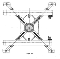
- the crane has four supports. Seen in the direction of travel shows a support 8 forward and is within the track. A support 9 points to the rear and lies within the track. A support 10 points to the left and is out of the track. A support 11 points to the right and is out of the track. In this arrangement, all columns are claimed as pure bending beam. Also, the middle piece 6 and the caterpillars 11 are not claimed to torsion. The connection of the supports 17 to 20 to the caterpillars 11 and to the middle piece 6 happen in each case vertically and in places with sufficient space.
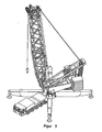
- FIG. 2 shows a crane according to the invention seen from behind.
- the superstructure 12 with boom 13 and counterweight 14 is rotatably connected via a rotary joint 15 with the center piece 6.
- the columns can be relatively long in this arrangement, whereby large moments occur in the supports. Since the left support 10 are passed through the bead 3, the height of the support 10 is limited by the height of the beads.
- the type of connection of the right support 11 removes this restriction.
- the underside of the support 11 is connected to the right-hand caterpillar. The top is struck against the center piece 6. Furthermore, it is possible to attach the support exclusively on the center piece 3. In this In case no modifications to the caterpillars have to be made. If the supports 10, 11 are connected to the center piece, this connection must be between the rotary joint and the connection to the beads.
- the rear support 9 is attached only to the center piece. To reduce the moment in the support, like the front support 8, it can be attached to both the center piece and the caterpillars. Of course, it is also possible to attach the supports 8, 9 only to the caterpillars.
- FIG. 3 shows a further advantageous embodiment.
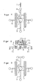
- a support 16 is designed such that a tilting edge is formed on the support. Based on FIGS. 4 and 5 the advantage is explained.
- FIG. 4 schematically four supports 17 are shown, which are arranged centrally to the center of rotation 2.
- the connecting line 18 between the ends of each two adjacent supports is referred to as tilting edge 18.
- a support 16 FIGS. 4 and 5
- FIG. 6 shows a typical conventional support.
- a hydraulic cylinder 21 is mounted, which is connected via a ball joint 22 with a support plate 23.
- the ball joint ensures that small uneven floors are compensated.
- a support according to the invention must at the end of a Have tilting edge.
- FIG. 7 One possible copy ( FIG. 7 ) consists of a support with a support cylinder 21 and two additional supports 24 which are mounted laterally in the front region of the support beam 20 on a cross member 25. In normal crane operation, the middle support cylinder 21 is used. To activate the additional support edge, the lateral supports 24 are extended. This can be done hydraulically or by spindle drive.
- FIG. 8 Another embodiment shows FIG. 8 , In the front area, two support cylinders 26, 27 are attached to a transverse bar 29. About ball joints they are connected to a support mat 28. To exclude Verzwteilungs theory, one of the cylinder 27 is rotatably mounted in the crossbar 29. When the additional tilting edge is activated, the hydraulic oil is locked in the cylinders. The arrangement is then rigid. In normal crane operation (standard support base), the cylinders are hydraulically balanced so that oil can flow freely from one cylinder to the other. Thus, the support mat is rotatable about a point between the cylinders. This possibility of being able to switch between normal operation and operation with extended tilting edge is not absolutely necessary. However, this ensures that the ground pressure distribution under the support mat 28 is uniform.
Landscapes
- Engineering & Computer Science (AREA)
- Mechanical Engineering (AREA)
- Jib Cranes (AREA)
- Iron Core Of Rotating Electric Machines (AREA)
- Forklifts And Lifting Vehicles (AREA)
- Valve Device For Special Equipments (AREA)
- Vehicle Body Suspensions (AREA)
- Vehicle Cleaning, Maintenance, Repair, Refitting, And Outriggers (AREA)
Abstract
Description
- Die Erfindung betrifft einen Kran gemäß dem Oberbegriff des Anspruchs 1.
- Krane mit gummibereiftem Fahrwerk sind in der Regel mit Stützen ausgestattet (siehe
Figur 9 ). Das Heben von Lasten ist in der Regel nur möglich, wenn der Kran auf den Stützen steht. Krane mit Raupenfahrwerk haben meist keine Stützen, sondern heben Lasten auf den Raupen stehend und können meist auch mit der Last verfahren. Um eine größere Stützbasis zu erhalten, können auch Raupenkrane zusätzlich mit Stützen ausgestattet werden.Figur 10 zeigt den Unterwagen des Demag CC/PC 3800. Die wichtigsten Komponenten sind inFigur 11 schematisch dargestellt, wobei die Fahrtrichtung durch den Pfeil 1 angedeutet ist. Von der Drehmitte 2 reichen vier Arme 4 zu den Raupen 3. An den Außenseiten der Raupen sind vier Stützen 5 befestigt. Ein solcher Kran kann sowohl auf den Raupen stehend, als auch auf den Stützen stehend betrieben werden. Diese Anordnung hat im Betrieb auf Stützen einen direkten Kraftverlauf, was erstrebenswert ist. Allerdings müssen die Kräfte und Momente durch die Raupen 11 durchgeleitet werden. Am Ende der Raupen befinden sich Umlenkräder, Getriebe und Kettenspanneinrichtungen. Dadurch ist es schwer, an dieser Stelle die Kräfte durchzuleiten.Figur 12 zeigt einen Unterwagen ähnlichFigur 11 . Hier sind die Raupen über ein Mittelstück 6 miteinander verbunden. Dieses Mittelstück ist die übliche Konstruktion für einen Raupenkran ohne Stützen. In der Mitte des Raupenträgers ist in der Regel ausreichend Platz. Daher ist die Montage und die Verbolzung der Komponenten relativ unproblematisch. - Im Stützenbetrieb sind die Kräfte in den Stützen in der Regel nicht gleichmäßig verteilt. Dadurch entsteht ein Torsionsmoment im Mittelstück 6 und auch in den Raupen 3. In
Figur 13 sind neben dem Mittelstück 6 auch die Stützen 7 an der Raupenmitte angebracht. Dadurch werden die Raupen 3 entlastet. - Der Erfindung liegt die Aufgabe zugrunde, einen Kran, insbesondere einen mobilen Kran auf schmalbauendem Raupenfahrwerk derart mit Stützen auszustatten, dass eine vergrößerte Stützbasis erreicht wird.
- Gelöst wird diese Aufgabe nach Anspruch 1 durch einen Kran, insbesondere einen mobilen Kran, bestehend aus einem Untergestell, einem Oberwagen und einem darauf angeordnete Ausleger, wobei der Oberwagen mit dem Untergestell über eine Drehverbindung verbunden ist und wobei mehrere Stützen am Kran vorgesehen sind, die zur Erhöhung der Stützbasis dienen, die sowohl für stationäre Krane als auch für mobile Krane vorteilhaft ist, wobei vier Stützarme vorgesehen sind, die weitestgehend zentrisch zur Drehmitte angeordnet sind, wobei zumindest eine der Stützen derart ausgebildet ist, dass sie sich auf mindestens zwei Punkten abstützt und die Verbindungslinie dieser Punkte eine Kippkante bildet. Dabei kann am Kopf der Stütze ein Querträger befestigt sein und im Abstand voneinander sind am Querträger zwei Stützzylinder vorgesehen.
- Die Stützzylinder können beispielsweise hydraulisch oder mittels eines Spindeltriebes ausfahrbar sein.
- Schließlich kann mittig zwischen den am Querträger angeordneten Stützzylindern ein weiterer Stützzylinder am Kopf der Stütze angeordnet sein.
- Die Stützzylinder können - nach einer weiteren Ausgestaltung - an ihren freien Enden über Kugelgelenke mit einer Stützmatte verbunden sein und es ist möglich, dass einer der am Querträger angeordneten Stützzylinder um seine Längsachse drehbar in diesem gelagert ist, um eventuelle Verzwängungskräfte auszuschließen.
- Eine vorteilhafte Ausgestaltung besteht darin, dass der Unterwagen aus einem Mittelstück und an zwei Seiten des Mittelstücks parallel zueinander angeordneten Raupenfahrwerken besteht,
dass vier Stützen vorgesehen sind, die mit dem Unterwagen verbunden sind, wobei deren Ausrichtung derart fixiert ist, dass sie jeweils einen Winkel von 90° miteinander einschließen,
wobei zwei der Stützen in Längsrichtung des Unterwagens und zwei quer dazu ausgerichtet sind. - Durch die Anordnung der Stützen in Längsrichtung bzw. quer zum Unterwagen ergibt sich ein direkter Kraftfluss. Dadurch treten keine vermeidbaren Momente auf. Die auftretenden Kräfte und Spannungen sind kleiner. Weniger Material wird benötigt. Gewicht und Kosten werden reduziert. Außerdem ist die Verbindungsstelle von Stützen an das Fahrwerk stets rechtwinklig. Dies ist im Allgemeinen leichter und schneller zu montieren als eine schräge Verbindungsstelle. Auch ist der Platzbedarf für die Verbindung geringer.
- Vorzugsweise sind die Stützen parallel zu den Raupen und senkrecht zu den Raupen angeordnet und schneiden sich in der Drehmitte. Die konkrete Ausgestaltung kann davon abweichen. Es gilt jedoch, dass die Enden der Stützen quer zur Fahrtrichtung außerhalb der Spur liegen und dass die Stützen längs der Fahrtrichtung innerhalb der Spur liegen.
- Die Anbindung der Stützen an den Unterwagen kann nach einer Ausführung dadurch erfolgen, dass von den quer ausgerichteten Stützen zumindest eine direkt am Raupenfahrwerk angebracht ist.
- Es kann aber auch eine der seitlichen Stützen mit ihrer Unterseite mit dem zugewandten Raupenfahrwerk verbunden sein, während deren Oberseite am Mittelstück befestigt ist.
- Die Stützen in Längsrichtung können direkt am Mittelstück befestigt werden, oder an der zum Mittelstück weisenden Seite des Raupenfahrwerks, oder an Mittelstück und Raupenfahrwerk befestigt werden.
- Nach einer weiteren Ausgestaltung können die Stützen leicht teleskopierbar ausgestaltet, nach oben oder seitlich klappbar sein.
- Am Kopf der Stützen sind ausfahrbare, den Kontakt zur Stützfläche herstellende Stützzylinder angeordnet.
- Die Erfindung soll nachfolgend an den Zeichnungen näher erläutert werden.
- Dabei zeigen:
- Figur 1
- eine Aufsicht auf das Raupenfahrwerk mit Stützen,
- Figur 2
- eine Ansicht von hinten,
- Figur 3
- eine abgewandelte Ausführung der Stützen mit Kippkante,
- Figur 4 und 5
- Erklärungen zur Kippkante,
- Figur 6 bis 8
- Ausbildungen einer Stütze, und
- Figur 9 bis 13
- Darstellungen zum Stand der Technik.
- Gemäß der Erfindung (
Figur 1 ) besitzt der Kran vier Stützen. In Fahrtrichtung gesehen zeigt eine Stütze 8 nach vorne und liegt innerhalb der Spur. Eine Stütze 9 zeigt nach hinten und liegt innerhalb der Spur. Eine Stütze 10 zeigt nach links und liegt außerhalb der Spur. Eine Stütze 11 zeigt nach rechts und liegt außerhalb der Spur. Bei dieser Anordnung werden alle Stützen als reine Biegeträger beansprucht. Auch das Mittelstück 6 und die Raupen 11 werden nicht auf Torsion beansprucht. Der Anschluss der Stützen 17 bis 20 an die Raupen 11 bzw. an das Mittelstück 6 geschehen jeweils senkrecht und an Stellen mit ausreichend Platz. -
Figur 2 zeigt einen erfindungsgemäßen Kran von hinten gesehen. Der Oberwagen 12 mit Ausleger 13 und Gegengewicht 14 ist über eine Drehverbindung 15 mit dem Mittelstück 6 drehbar verbunden. Wie inFigur 2 zu sehen ist, können bei dieser Anordnung die Stützen relativ lang werden, wodurch große Momente in den Stützen auftreten. Da die linke Stütze 10 durch die Raupe 3 hindurchgeführt werden, ist die Höhe der Stütze 10 durch die Höhe der Raupen begrenzt. - Die Art der Anbindung der rechten Stütze 11 hebt diese Beschränkung auf. Die Unterseite der Stütze 11 wird mit der rechten Raupe verbunden. Die Oberseite wird an das Mittelstück 6 angeschlagen. Weiterhin ist es möglich, die Stütze ausschließlich am Mittelstück 3 zu befestigen. In diesem Fall müssen keine Modifikationen an den Raupen vorgenommen werden. Falls die Stützen 10, 11 mit dem Mittelstück verbunden werden, muss diese Verbindung zwischen der Drehverbindung und der Verbindung zu den Raupen liegen. Die hintere Stütze 9 ist nur am Mittelstück befestigt. Um das Moment in der Stütze zu reduzieren, kann sie wie die vordere Stütze 8 sowohl am Mittelstück, als auch an den Raupen befestigt werden. Selbstverständlich ist es auch möglich, die Stützen 8, 9 nur an den Raupen zu befestigen.
-
Figur 3 zeigt eine weitere vorteilhafte Ausführungsform. Eine Stütze 16 wird derart gestaltet, so dass eine Kippkante an der Stütze entsteht. Anhand derFiguren 4 und 5 wird der Vorteil erläutert. InFigur 4 sind schematisch vier Stützen 17 dargestellt, die zentrisch zur Drehmitte 2 angeordnet sind. Die Verbindungslinie 18 zwischen den Enden je zwei benachbarter Stützen wird als Kippkante 18 bezeichnet. Sollte der Kran seine Standsicherheit verlieren (Unfall), würde er über diese Kante 18 kippen. Wird eine Stütze 16 (Figuren 4 und 5 ) so ausgeführt, dass sie auf zwei Punkten steht, entsteht eine Kippkante 19, die einen größeren Abstand zur Drehmitte aufweist als die herkömmlichen Kippkanten 18. Dadurch ergibt sich ein erhöhtes Lastmoment, wenn der Ausleger über dieser Stütze steht. Dieses erhöhte Lastmoment kann genutzt werden, um besonders schwere Hübe durchzuführen oder um besonders lange Ausleger vom Boden aufzurichten. - Anhand der
Figuren 6, 7 und 8 werden mögliche Ausführungsformen derartiger Stützen erläutert.Figur 6 zeigt eine typische herkömmliche Stütze. Am Ende des Stützträgers 20 ist ein Hydraulikzylinder 21 angebracht, der über ein Kugelgelenk 22 mit einem Stützteller 23 verbunden ist. Durch das Kugelgelenk wird sichergestellt, dass kleine Bodenunebenheiten ausgeglichen werden. Eine erfindungsgemäße Stütze muss an deren Ende eine Kippkante aufweisen. Eine mögliche Ausfertigung (Figur 7 ) besteht aus einer Stütze mit einem Stützzylinder 21 und zwei zusätzlichen Stützen 24, die seitlich im vorderen Bereich des Stützträgers 20 an einem Querträger 25 angebracht werden. Im normalen Kranbetrieb wird der mittlere Stützzylinder 21 verwendet. Um die zusätzliche Stützkante zu aktivieren, werden die seitlichen Stützen 24 ausgefahren. Dies kann hydraulisch oder mittels Spindelantrieb geschehen. Auch klappbare oder steckbare Stützen sind möglich. Eine andere Ausführungsform zeigtFigur 8 . Im vorderen Bereich sind zwei Stützzylinder 26, 27 an einem Querbalken 29 angebracht. Über Kugelgelenke sind sie mit einer Stützmatte 28 verbunden. Um Verzwängungskräfte auszuschließen, ist einer der Zylinder 27 drehbar im Querbalken 29 gelagert. Bei aktivierter zusätzlicher Kippkante wird das Hydrauliköl in den Zylindern eingesperrt. Die Anordnung ist dann starr. Im normalen Kranbetrieb (Standard-Stützbasis) werden die Zylinder hydraulisch gleichgeschaltet, so dass Öl ungehindert von einem Zylinder in den anderen fließen kann. Damit ist die Stützmatte um einen Punkt zwischen den Zylindern drehbar. Diese Möglichkeit, zwischen normalem Betrieb und Betrieb mit erweiterter Kippkante umschalten zu können, ist nicht zwingend notwendig. Dadurch wird allerdings gewährleistet, dass die Bodendruckverteilung unter der Stützmatte 28 gleichmäßig ist.
Claims (10)
- Kran, umfassend- ein Untergestell,- einen Oberwagen und- einen auf dem Oberwagen angeordneten Ausleger,wobei- der Oberwagen mit dem Untergestell über eine Drehverbindung verbunden ist und- mehrere Stützen am Kran vorgesehen sind,dadurch gekennzeichnet, dass
mindestens vier Stützarme vorgesehen sind, die weitestgehend zentrisch zur Drehmitte angeordnet sind, wobei mindestens eine der Stützen derart ausgebildet ist, dass sie sich auf mindestens zwei Punkten abstützt und die Verbindungslinie dieser Punkte eine Kippkante bildet. - Kran nach Anspruch 1, dadurch gekennzeichnet, dass am Kopf der Stütze ein Querträger befestigt ist und dass im Abstand voneinander am Querträger zwei Stützzylinder vorgesehen sind.
- Kran nach Anspruch 2, dadurch gekennzeichnet, dass die Stützzylinder hydraulisch ausfahrbar sind.
- Kran nach Anspruch 2, dadurch gekennzeichnet, dass die Stützzylinder mittels eines Spindeltriebes ausfahrbar sind.
- Kran nach einem der Ansprüche 2 bis 4, dadurch gekennzeichnet, dass mittig zwischen den am Querträger angeordneten Stützzylindern ein weiterer Stützzylinder am Kopf der Stütze angeordnet ist.
- Kran nach einem der Ansprüche 2 bis 5, dadurch gekennzeichnet, dass die Stützzylinder an ihren freien Enden über Kugelgelenke mit einer Stützmatte verbunden sind.
- Kran nach einem der Ansprüche 2 bis 6, dadurch gekennzeichnet, dass einer der am Querträger angeordneten Stützzylinder um seine Längsachse drehbar in diesem gelagert ist.
- Kran, insbesondere mobiler Kran, nach Anspruch 1, dadurch gekennzeichnet, dass- das Untergestell ein Unterwagen ist,- die Stützen am Kran der Erhöhung der Stützbasis dienen,- der Unterwagen ein Mittelstück und an zwei Seiten des Mittelstückes parallel zueinander angeordnete Raupenfahrwerke umfasst,- vier Stützen vorgesehen sind, die mit dem Unterwagen verbunden sind, und- eine Ausrichtung der Stützen derart fixiert ist, dass zwei der Stützen längs einer Fahrtrichtung und innerhalb der Spur des Unterwagens zwei quer dazu außerhalb der Spur des Unterwagens ausgerichtet sind.
- Kran nach einem der vorgehenden Ansprüche, dadurch gekennzeichnet, dass mindestens eine Stütze teleskopierbar ist.
- Kran nach einem der vorgehenden Ansprüche, dadurch gekennzeichnet, dass mindestens eine Stütze nach oben oder seitlich klappbar ist.
Applications Claiming Priority (2)
| Application Number | Priority Date | Filing Date | Title |
|---|---|---|---|
| DE102005047745A DE102005047745A1 (de) | 2005-09-28 | 2005-09-28 | Kran, insbesondere mobiler Kran mit schmaler Spur und erweiterter Stützbasis |
| EP06775898A EP1928778B1 (de) | 2005-09-28 | 2006-08-22 | Kran, insbesondere mobiler kran mit schmaler spur und erweiterter stützbasis |
Related Parent Applications (3)
| Application Number | Title | Priority Date | Filing Date |
|---|---|---|---|
| EP06775898.7 Division | 2006-08-22 | ||
| EP06775898A Division EP1928778B1 (de) | 2005-09-28 | 2006-08-22 | Kran, insbesondere mobiler kran mit schmaler spur und erweiterter stützbasis |
| EP06775898A Division-Into EP1928778B1 (de) | 2005-09-28 | 2006-08-22 | Kran, insbesondere mobiler kran mit schmaler spur und erweiterter stützbasis |
Publications (3)
| Publication Number | Publication Date |
|---|---|
| EP2088115A2 true EP2088115A2 (de) | 2009-08-12 |
| EP2088115A3 EP2088115A3 (de) | 2009-08-19 |
| EP2088115B1 EP2088115B1 (de) | 2010-11-10 |
Family
ID=37395775
Family Applications (2)
| Application Number | Title | Priority Date | Filing Date |
|---|---|---|---|
| EP06775898A Expired - Lifetime EP1928778B1 (de) | 2005-09-28 | 2006-08-22 | Kran, insbesondere mobiler kran mit schmaler spur und erweiterter stützbasis |
| EP09006475A Expired - Lifetime EP2088115B1 (de) | 2005-09-28 | 2006-08-22 | Kran |
Family Applications Before (1)
| Application Number | Title | Priority Date | Filing Date |
|---|---|---|---|
| EP06775898A Expired - Lifetime EP1928778B1 (de) | 2005-09-28 | 2006-08-22 | Kran, insbesondere mobiler kran mit schmaler spur und erweiterter stützbasis |
Country Status (9)
| Country | Link |
|---|---|
| US (2) | US8499945B2 (de) |
| EP (2) | EP1928778B1 (de) |
| JP (1) | JP5405112B2 (de) |
| CN (1) | CN101277894B (de) |
| AT (2) | ATE457294T1 (de) |
| CA (1) | CA2623713A1 (de) |
| DE (4) | DE102005047745A1 (de) |
| ES (2) | ES2339155T3 (de) |
| WO (1) | WO2007036188A2 (de) |
Cited By (1)
| Publication number | Priority date | Publication date | Assignee | Title |
|---|---|---|---|---|
| WO2019228590A1 (de) * | 2018-05-30 | 2019-12-05 | David Mann | Stabilisierungseinrichtung und verfahren zum erhöhen der standsicherheit mobiler baumaschinen |
Families Citing this family (13)
| Publication number | Priority date | Publication date | Assignee | Title |
|---|---|---|---|---|
| US9284168B2 (en) * | 2009-10-01 | 2016-03-15 | Mw Industries, Inc. | Guyless service rig with side-mounted, pivotally deployable rear outriggers |
| DE102011102110B4 (de) | 2011-05-20 | 2023-05-17 | Liebherr-Werk Ehingen Gmbh | Unterwagen für Raupenkran, Raupenkran und Verfahren zum Auf- und Abbau eines Raupenkrans |
| DE102012001930A1 (de) | 2012-02-02 | 2013-08-08 | LTK GmbH | Vorrichtung zur kontinuierlichen Bestimmung der Standsicherheit und Verfahren zur Überwachung der Standsicherheit |
| US9238945B2 (en) | 2013-02-15 | 2016-01-19 | Black Hawk Energy Services, Inc. | Base beam and self-propelled derrick rig assembly |
| US20140231609A1 (en) * | 2013-02-15 | 2014-08-21 | Black Hawk Energy Services | Base beam for supporting a self-propelled derrick rig |
| US9212524B2 (en) | 2013-02-15 | 2015-12-15 | Black Hawk Energy Services, Inc. | Methods of supporting a self-propelled derrick rig |
| DE202016004687U1 (de) * | 2016-07-29 | 2017-11-02 | Liebherr-Werk Nenzing Gmbh | Mobile Arbeitsmaschine |
| DE102016011189B4 (de) * | 2016-09-15 | 2024-06-27 | Liebherr-Werk Ehingen Gmbh | Vorrichtung zum Stabilisieren eines Krans |
| CN107572433B (zh) * | 2017-10-11 | 2019-01-08 | 徐工集团工程机械有限公司 | 一种随车起重机防倾翻系统及方法 |
| CN111847285B (zh) * | 2020-08-13 | 2023-06-02 | 合肥工业大学 | 一种适用于柔索并联起重机器人的稳定调节机构及调节方法 |
| CN114408776B (zh) * | 2022-01-24 | 2023-03-10 | 浙江三一装备有限公司 | 起重机及其起臂方法 |
| CN116812786A (zh) * | 2023-05-31 | 2023-09-29 | 徐州建机工程机械有限公司 | 履带底盘及履带式塔机 |
| CN119872480A (zh) * | 2025-01-20 | 2025-04-25 | 中联重科股份有限公司 | 工程底盘及工程机械 |
Citations (1)
| Publication number | Priority date | Publication date | Assignee | Title |
|---|---|---|---|---|
| DE2517203A1 (de) | 1975-04-18 | 1976-10-21 | Liebherr Werk Ehingen | Autokran |
Family Cites Families (37)
| Publication number | Priority date | Publication date | Assignee | Title |
|---|---|---|---|---|
| DE129892C (de) | ||||
| US527741A (en) * | 1894-10-16 | Means for supporting dredge or other structures | ||
| US2131479A (en) * | 1936-07-11 | 1938-09-27 | Clyde Iron Works | Loading hoist |
| US2139960A (en) * | 1937-08-11 | 1938-12-13 | Roy D Kauffman | Crane |
| US2910189A (en) * | 1956-08-02 | 1959-10-27 | Maschf Augsburg Nuernberg Ag | Rotary automobile crane |
| US2914194A (en) * | 1957-08-21 | 1959-11-24 | American Hoist & Derrick Co | Outrigger construction for carrier mounted cranes |
| US3021016A (en) * | 1959-12-15 | 1962-02-13 | Thew Shovel Co | Outriggers for crawler cranes, shovels, hoes and the like |
| US3878944A (en) * | 1973-08-30 | 1975-04-22 | Dantel E Beduhn | Crane support structure |
| DE2364296C3 (de) * | 1973-12-22 | 1980-01-24 | Fritz 5802 Wetter Metz | Abstützvorrichtung für Krane, Hebebühnen o.dgl |
| DD129892A1 (de) * | 1977-02-24 | 1978-02-15 | Rudolf Schulze | Abstuetzvorrichtung fuer kraftfahrzeuge,insbesondere eisenbahnkrane |
| GB1554735A (en) * | 1977-10-06 | 1979-10-31 | 600 Group Ltd | Crane carriers |
| US4196816A (en) * | 1977-11-01 | 1980-04-08 | Fmc Corporation | Heavy duty crane |
| US4273244A (en) * | 1979-01-29 | 1981-06-16 | Fmc Corporation | Crane upperstructure self-transferring system |
| US4394911A (en) * | 1980-04-08 | 1983-07-26 | Fmc Corporation | Heavy duty crane |
| EP0048076A1 (de) * | 1980-08-18 | 1982-03-24 | AMERICAN HOIST & DERRICK COMPANY | Fahrbare Kranstruktur |
| US4394913A (en) * | 1980-11-07 | 1983-07-26 | Harnischfeger Corporation | Crane having power operated outriggers and lock means therefor |
| US4394912A (en) | 1980-11-07 | 1983-07-26 | Harnischfeger Corporation | Mobile crane having telescoping outriggers and power operated screw means for same |
| US4387814A (en) * | 1981-09-08 | 1983-06-14 | The Manitowoc Company, Inc. | Traveling attachment for ring supported lift crane |
| US4446976A (en) * | 1982-02-16 | 1984-05-08 | Fmc Corporation | Reversible outrigger crane support |
| DD212722B1 (de) * | 1982-12-24 | 1986-10-29 | Sommerfeld Hans Ulrich | Bodenabstuetzung, insbesondere fuer krane oder bagger |
| FR2541661B1 (fr) * | 1983-02-24 | 1986-01-31 | Ppm Sa | Ensemble de stabilisation pour engin mobile |
| DE3310491A1 (de) * | 1983-03-23 | 1984-10-04 | O & K Orenstein & Koppel Ag, 1000 Berlin | Abstuetzvorrichtung an kettenfahrzeugen |
| JPS609896U (ja) | 1983-06-29 | 1985-01-23 | 株式会社神戸製鋼所 | 移動式クレ−ンの五点支持式アウトリガ装置 |
| US4579234A (en) * | 1984-03-16 | 1986-04-01 | American Hoist & Derrick Company | Self-erecting mobile crane |
| JPS60170392U (ja) | 1984-04-18 | 1985-11-12 | 株式会社小松製作所 | クレ−ンのアウトリガ装置 |
| CH667448A5 (de) * | 1985-02-15 | 1988-10-14 | Ernst Zimmermann | Unterwagen eines schwerlastfahrzeuges, insbesondere eines mehrachsigen mobilkranes. |
| JPH0768702B2 (ja) * | 1990-05-28 | 1995-07-26 | 日本車輌製造株式会社 | 大型杭打機の分解輸送方法 |
| JPH07228485A (ja) * | 1994-02-18 | 1995-08-29 | Hitachi Constr Mach Co Ltd | 建設機械における走行体の伸縮検出装置 |
| DE29613415U1 (de) * | 1996-08-02 | 1996-09-19 | Compact Truck Ag, Zug | Kranfahrzeug |
| CA2266791C (en) * | 1998-03-27 | 2005-02-01 | Manitowoc Crane Group, Inc. | Four track crawler crane |
| JP4763119B2 (ja) | 1999-08-04 | 2011-08-31 | リープヘル−ヴェルク エーインゲン ゲーエムベーハー | クローラー搭載式クレーン |
| DE10020270B4 (de) * | 1999-08-04 | 2020-03-26 | Liebherr-Werk Ehingen Gmbh | Raupenkran |
| DE10023077C2 (de) * | 2000-05-05 | 2002-07-11 | Mannesmann Ag | Abstützung für ein gleisgebundenes Kranfahrzeug, insbesondere für ein Zweiwegefahrzeug |
| DE10143716B4 (de) * | 2001-08-30 | 2004-04-15 | Terex-Demag Gmbh & Co. Kg | Mobiles Arbeitsgerät mit Stützträgern und Verfahren zum Betrieb dieses Arbeitsgeräts |
| US6848522B2 (en) * | 2002-04-19 | 2005-02-01 | Link-Belt Construction Equipment Co. L.P. , Lllp | Systems for connecting a ground-engaging motive device to a vehicle and related methods |
| DE20305683U1 (de) * | 2003-04-08 | 2004-08-19 | Liebherr-Werk Ehingen Gmbh | Fahrbarer Kran |
| US7328810B1 (en) * | 2003-12-22 | 2008-02-12 | Lester Kent Rhodes | Crane supporting apparatus |
-
2005
- 2005-09-28 DE DE102005047745A patent/DE102005047745A1/de not_active Withdrawn
-
2006
- 2006-08-22 DE DE202006020705U patent/DE202006020705U1/de not_active Expired - Lifetime
- 2006-08-22 US US11/992,718 patent/US8499945B2/en active Active
- 2006-08-22 DE DE502006008304T patent/DE502006008304D1/de not_active Expired - Lifetime
- 2006-08-22 EP EP06775898A patent/EP1928778B1/de not_active Expired - Lifetime
- 2006-08-22 ES ES06775898T patent/ES2339155T3/es not_active Expired - Lifetime
- 2006-08-22 AT AT06775898T patent/ATE457294T1/de active
- 2006-08-22 CA CA002623713A patent/CA2623713A1/en not_active Abandoned
- 2006-08-22 WO PCT/DE2006/001479 patent/WO2007036188A2/de not_active Ceased
- 2006-08-22 AT AT09006475T patent/ATE487675T1/de active
- 2006-08-22 DE DE502006006122T patent/DE502006006122D1/de not_active Expired - Lifetime
- 2006-08-22 JP JP2008532578A patent/JP5405112B2/ja not_active Expired - Lifetime
- 2006-08-22 ES ES09006475T patent/ES2352640T3/es not_active Expired - Lifetime
- 2006-08-22 EP EP09006475A patent/EP2088115B1/de not_active Expired - Lifetime
- 2006-08-22 CN CN2006800357652A patent/CN101277894B/zh not_active Expired - Fee Related
-
2010
- 2010-08-30 US US12/871,480 patent/US8225947B2/en active Active
Patent Citations (1)
| Publication number | Priority date | Publication date | Assignee | Title |
|---|---|---|---|---|
| DE2517203A1 (de) | 1975-04-18 | 1976-10-21 | Liebherr Werk Ehingen | Autokran |
Cited By (1)
| Publication number | Priority date | Publication date | Assignee | Title |
|---|---|---|---|---|
| WO2019228590A1 (de) * | 2018-05-30 | 2019-12-05 | David Mann | Stabilisierungseinrichtung und verfahren zum erhöhen der standsicherheit mobiler baumaschinen |
Also Published As
| Publication number | Publication date |
|---|---|
| US8225947B2 (en) | 2012-07-24 |
| EP2088115A3 (de) | 2009-08-19 |
| ES2339155T3 (es) | 2010-05-17 |
| EP2088115B1 (de) | 2010-11-10 |
| DE102005047745A1 (de) | 2007-03-29 |
| DE202006020705U1 (de) | 2009-08-13 |
| JP5405112B2 (ja) | 2014-02-05 |
| US20100320166A1 (en) | 2010-12-23 |
| US20090107946A1 (en) | 2009-04-30 |
| US8499945B2 (en) | 2013-08-06 |
| CA2623713A1 (en) | 2007-04-05 |
| WO2007036188A2 (de) | 2007-04-05 |
| WO2007036188A3 (de) | 2007-05-18 |
| CN101277894B (zh) | 2011-12-28 |
| CN101277894A (zh) | 2008-10-01 |
| DE502006006122D1 (de) | 2010-03-25 |
| DE502006008304D1 (de) | 2010-12-23 |
| ATE487675T1 (de) | 2010-11-15 |
| EP1928778B1 (de) | 2010-02-10 |
| JP2009509888A (ja) | 2009-03-12 |
| ATE457294T1 (de) | 2010-02-15 |
| ES2352640T3 (es) | 2011-02-22 |
| EP1928778A2 (de) | 2008-06-11 |
Similar Documents
| Publication | Publication Date | Title |
|---|---|---|
| EP0538721B1 (de) | Chassis für Raupenfahrzeuge | |
| EP1928778B1 (de) | Kran, insbesondere mobiler kran mit schmaler spur und erweiterter stützbasis | |
| EP1851159B1 (de) | Stützausleger für fahrbare arbeitsmaschinen | |
| DE102011102110B4 (de) | Unterwagen für Raupenkran, Raupenkran und Verfahren zum Auf- und Abbau eines Raupenkrans | |
| DE1944214B2 (de) | Chienenlos verfahrbarer drehkranunterwagen | |
| EP2218836A1 (de) | Fahrzeug, insbesondere Baufahrzeug | |
| DE2658250A1 (de) | Fahrbarer und hebbarer arbeitskorb | |
| DE102009016033A1 (de) | Gittermastkran und Gittermastausleger | |
| DE202021106818U1 (de) | Mobilkran mit einer Gegengewichtsvorrichtung | |
| DE3143802A1 (de) | Kranwagen mit teleskop-ausfahrstuetzen und kraftbetaetigten schraubenspindeleinrichtungen hierfuer | |
| DE20305683U1 (de) | Fahrbarer Kran | |
| DE2521623A1 (de) | Stuetzausleger bzw. bodenabstuetzung fuer fahrzeugkrane | |
| DE102014012661B4 (de) | Verfahren zum Betrieb eines Krans und Kran | |
| EP1760031B1 (de) | Transportoptimierter Kranunterwagen | |
| EP1516849B1 (de) | Kran | |
| AT523305A2 (de) | Fahrzeugkran | |
| EP1332896A1 (de) | Amphibisches Brücken- und Übersetzfahrzeug | |
| DE10143716B4 (de) | Mobiles Arbeitsgerät mit Stützträgern und Verfahren zum Betrieb dieses Arbeitsgeräts | |
| DE102008006119B3 (de) | Mobilkran und Verfahren zur Montage | |
| DE102020118775B4 (de) | Mobilkran mit Abstützvorrichtung | |
| DE202004016639U1 (de) | Mobilkran | |
| DE2818612C2 (de) | Untergestell für einen Kran oder dergleichen | |
| DE2262444B2 (de) | Abstützung für einen fahrbaren Kran | |
| EP0947385A2 (de) | Fahrbare Betonpumpe | |
| DE202006002023U1 (de) | Raupenkran |
Legal Events
| Date | Code | Title | Description |
|---|---|---|---|
| PUAI | Public reference made under article 153(3) epc to a published international application that has entered the european phase |
Free format text: ORIGINAL CODE: 0009012 |
|
| PUAL | Search report despatched |
Free format text: ORIGINAL CODE: 0009013 |
|
| AC | Divisional application: reference to earlier application |
Ref document number: 1928778 Country of ref document: EP Kind code of ref document: P |
|
| AK | Designated contracting states |
Kind code of ref document: A2 Designated state(s): AT BE BG CH CY CZ DE DK EE ES FI FR GB GR HU IE IS IT LI LT LU LV MC NL PL PT RO SE SI SK TR |
|
| AK | Designated contracting states |
Kind code of ref document: A3 Designated state(s): AT BE BG CH CY CZ DE DK EE ES FI FR GB GR HU IE IS IT LI LT LU LV MC NL PL PT RO SE SI SK TR |
|
| 17P | Request for examination filed |
Effective date: 20091008 |
|
| GRAP | Despatch of communication of intention to grant a patent |
Free format text: ORIGINAL CODE: EPIDOSNIGR1 |
|
| GRAS | Grant fee paid |
Free format text: ORIGINAL CODE: EPIDOSNIGR3 |
|
| GRAA | (expected) grant |
Free format text: ORIGINAL CODE: 0009210 |
|
| AC | Divisional application: reference to earlier application |
Ref document number: 1928778 Country of ref document: EP Kind code of ref document: P |
|
| AK | Designated contracting states |
Kind code of ref document: B1 Designated state(s): AT BE BG CH CY CZ DE DK EE ES FI FR GB GR HU IE IS IT LI LT LU LV MC NL PL PT RO SE SI SK TR |
|
| REG | Reference to a national code |
Ref country code: GB Ref legal event code: FG4D Free format text: NOT ENGLISH |
|
| REG | Reference to a national code |
Ref country code: CH Ref legal event code: EP |
|
| REG | Reference to a national code |
Ref country code: IE Ref legal event code: FG4D Free format text: LANGUAGE OF EP DOCUMENT: GERMAN |
|
| REF | Corresponds to: |
Ref document number: 502006008304 Country of ref document: DE Date of ref document: 20101223 Kind code of ref document: P |
|
| REG | Reference to a national code |
Ref country code: ES Ref legal event code: FG2A Effective date: 20110210 Ref country code: SE Ref legal event code: TRGR |
|
| REG | Reference to a national code |
Ref country code: NL Ref legal event code: VDEP Effective date: 20101110 |
|
| LTIE | Lt: invalidation of european patent or patent extension |
Effective date: 20101110 |
|
| PG25 | Lapsed in a contracting state [announced via postgrant information from national office to epo] |
Ref country code: LT Free format text: LAPSE BECAUSE OF FAILURE TO SUBMIT A TRANSLATION OF THE DESCRIPTION OR TO PAY THE FEE WITHIN THE PRESCRIBED TIME-LIMIT Effective date: 20101110 |
|
| PG25 | Lapsed in a contracting state [announced via postgrant information from national office to epo] |
Ref country code: CY Free format text: LAPSE BECAUSE OF FAILURE TO SUBMIT A TRANSLATION OF THE DESCRIPTION OR TO PAY THE FEE WITHIN THE PRESCRIBED TIME-LIMIT Effective date: 20101110 Ref country code: FI Free format text: LAPSE BECAUSE OF FAILURE TO SUBMIT A TRANSLATION OF THE DESCRIPTION OR TO PAY THE FEE WITHIN THE PRESCRIBED TIME-LIMIT Effective date: 20101110 Ref country code: NL Free format text: LAPSE BECAUSE OF FAILURE TO SUBMIT A TRANSLATION OF THE DESCRIPTION OR TO PAY THE FEE WITHIN THE PRESCRIBED TIME-LIMIT Effective date: 20101110 Ref country code: BG Free format text: LAPSE BECAUSE OF FAILURE TO SUBMIT A TRANSLATION OF THE DESCRIPTION OR TO PAY THE FEE WITHIN THE PRESCRIBED TIME-LIMIT Effective date: 20110210 Ref country code: LV Free format text: LAPSE BECAUSE OF FAILURE TO SUBMIT A TRANSLATION OF THE DESCRIPTION OR TO PAY THE FEE WITHIN THE PRESCRIBED TIME-LIMIT Effective date: 20101110 Ref country code: SI Free format text: LAPSE BECAUSE OF FAILURE TO SUBMIT A TRANSLATION OF THE DESCRIPTION OR TO PAY THE FEE WITHIN THE PRESCRIBED TIME-LIMIT Effective date: 20101110 Ref country code: IS Free format text: LAPSE BECAUSE OF FAILURE TO SUBMIT A TRANSLATION OF THE DESCRIPTION OR TO PAY THE FEE WITHIN THE PRESCRIBED TIME-LIMIT Effective date: 20110310 Ref country code: PT Free format text: LAPSE BECAUSE OF FAILURE TO SUBMIT A TRANSLATION OF THE DESCRIPTION OR TO PAY THE FEE WITHIN THE PRESCRIBED TIME-LIMIT Effective date: 20110310 |
|
| REG | Reference to a national code |
Ref country code: IE Ref legal event code: FD4D |
|
| PG25 | Lapsed in a contracting state [announced via postgrant information from national office to epo] |
Ref country code: GR Free format text: LAPSE BECAUSE OF FAILURE TO SUBMIT A TRANSLATION OF THE DESCRIPTION OR TO PAY THE FEE WITHIN THE PRESCRIBED TIME-LIMIT Effective date: 20110211 |
|
| PG25 | Lapsed in a contracting state [announced via postgrant information from national office to epo] |
Ref country code: CZ Free format text: LAPSE BECAUSE OF FAILURE TO SUBMIT A TRANSLATION OF THE DESCRIPTION OR TO PAY THE FEE WITHIN THE PRESCRIBED TIME-LIMIT Effective date: 20101110 Ref country code: IE Free format text: LAPSE BECAUSE OF FAILURE TO SUBMIT A TRANSLATION OF THE DESCRIPTION OR TO PAY THE FEE WITHIN THE PRESCRIBED TIME-LIMIT Effective date: 20101110 Ref country code: EE Free format text: LAPSE BECAUSE OF FAILURE TO SUBMIT A TRANSLATION OF THE DESCRIPTION OR TO PAY THE FEE WITHIN THE PRESCRIBED TIME-LIMIT Effective date: 20101110 |
|
| PG25 | Lapsed in a contracting state [announced via postgrant information from national office to epo] |
Ref country code: PL Free format text: LAPSE BECAUSE OF FAILURE TO SUBMIT A TRANSLATION OF THE DESCRIPTION OR TO PAY THE FEE WITHIN THE PRESCRIBED TIME-LIMIT Effective date: 20101110 Ref country code: RO Free format text: LAPSE BECAUSE OF FAILURE TO SUBMIT A TRANSLATION OF THE DESCRIPTION OR TO PAY THE FEE WITHIN THE PRESCRIBED TIME-LIMIT Effective date: 20101110 Ref country code: DK Free format text: LAPSE BECAUSE OF FAILURE TO SUBMIT A TRANSLATION OF THE DESCRIPTION OR TO PAY THE FEE WITHIN THE PRESCRIBED TIME-LIMIT Effective date: 20101110 Ref country code: SK Free format text: LAPSE BECAUSE OF FAILURE TO SUBMIT A TRANSLATION OF THE DESCRIPTION OR TO PAY THE FEE WITHIN THE PRESCRIBED TIME-LIMIT Effective date: 20101110 |
|
| PLBE | No opposition filed within time limit |
Free format text: ORIGINAL CODE: 0009261 |
|
| STAA | Information on the status of an ep patent application or granted ep patent |
Free format text: STATUS: NO OPPOSITION FILED WITHIN TIME LIMIT |
|
| 26N | No opposition filed |
Effective date: 20110811 |
|
| REG | Reference to a national code |
Ref country code: DE Ref legal event code: R097 Ref document number: 502006008304 Country of ref document: DE Effective date: 20110811 |
|
| PG25 | Lapsed in a contracting state [announced via postgrant information from national office to epo] |
Ref country code: IT Free format text: LAPSE BECAUSE OF FAILURE TO SUBMIT A TRANSLATION OF THE DESCRIPTION OR TO PAY THE FEE WITHIN THE PRESCRIBED TIME-LIMIT Effective date: 20101110 |
|
| BERE | Be: lapsed |
Owner name: TEREX DEMAG G.M.B.H. Effective date: 20110831 |
|
| PG25 | Lapsed in a contracting state [announced via postgrant information from national office to epo] |
Ref country code: MC Free format text: LAPSE BECAUSE OF NON-PAYMENT OF DUE FEES Effective date: 20110831 |
|
| REG | Reference to a national code |
Ref country code: CH Ref legal event code: PL |
|
| PG25 | Lapsed in a contracting state [announced via postgrant information from national office to epo] |
Ref country code: LI Free format text: LAPSE BECAUSE OF NON-PAYMENT OF DUE FEES Effective date: 20110831 Ref country code: CH Free format text: LAPSE BECAUSE OF NON-PAYMENT OF DUE FEES Effective date: 20110831 |
|
| REG | Reference to a national code |
Ref country code: FR Ref legal event code: ST Effective date: 20120430 |
|
| PG25 | Lapsed in a contracting state [announced via postgrant information from national office to epo] |
Ref country code: BE Free format text: LAPSE BECAUSE OF NON-PAYMENT OF DUE FEES Effective date: 20110831 |
|
| PG25 | Lapsed in a contracting state [announced via postgrant information from national office to epo] |
Ref country code: FR Free format text: LAPSE BECAUSE OF NON-PAYMENT OF DUE FEES Effective date: 20110831 |
|
| REG | Reference to a national code |
Ref country code: AT Ref legal event code: MM01 Ref document number: 487675 Country of ref document: AT Kind code of ref document: T Effective date: 20110822 |
|
| PG25 | Lapsed in a contracting state [announced via postgrant information from national office to epo] |
Ref country code: AT Free format text: LAPSE BECAUSE OF NON-PAYMENT OF DUE FEES Effective date: 20110822 |
|
| PG25 | Lapsed in a contracting state [announced via postgrant information from national office to epo] |
Ref country code: LU Free format text: LAPSE BECAUSE OF NON-PAYMENT OF DUE FEES Effective date: 20110822 |
|
| PG25 | Lapsed in a contracting state [announced via postgrant information from national office to epo] |
Ref country code: TR Free format text: LAPSE BECAUSE OF FAILURE TO SUBMIT A TRANSLATION OF THE DESCRIPTION OR TO PAY THE FEE WITHIN THE PRESCRIBED TIME-LIMIT Effective date: 20101110 |
|
| PG25 | Lapsed in a contracting state [announced via postgrant information from national office to epo] |
Ref country code: HU Free format text: LAPSE BECAUSE OF FAILURE TO SUBMIT A TRANSLATION OF THE DESCRIPTION OR TO PAY THE FEE WITHIN THE PRESCRIBED TIME-LIMIT Effective date: 20101110 |
|
| PGFP | Annual fee paid to national office [announced via postgrant information from national office to epo] |
Ref country code: GB Payment date: 20130821 Year of fee payment: 8 |
|
| PGFP | Annual fee paid to national office [announced via postgrant information from national office to epo] |
Ref country code: SE Payment date: 20140820 Year of fee payment: 9 Ref country code: ES Payment date: 20140826 Year of fee payment: 9 |
|
| GBPC | Gb: european patent ceased through non-payment of renewal fee |
Effective date: 20140822 |
|
| PG25 | Lapsed in a contracting state [announced via postgrant information from national office to epo] |
Ref country code: GB Free format text: LAPSE BECAUSE OF NON-PAYMENT OF DUE FEES Effective date: 20140822 |
|
| REG | Reference to a national code |
Ref country code: SE Ref legal event code: EUG |
|
| PG25 | Lapsed in a contracting state [announced via postgrant information from national office to epo] |
Ref country code: SE Free format text: LAPSE BECAUSE OF NON-PAYMENT OF DUE FEES Effective date: 20150823 |
|
| REG | Reference to a national code |
Ref country code: DE Ref legal event code: R082 Ref document number: 502006008304 Country of ref document: DE Representative=s name: MOSER GOETZE & PARTNER PATENTANWAELTE MBB, DE Ref country code: DE Ref legal event code: R082 Ref document number: 502006008304 Country of ref document: DE Representative=s name: RAU, SCHNECK & HUEBNER PATENTANWAELTE RECHTSAN, DE Ref country code: DE Ref legal event code: R081 Ref document number: 502006008304 Country of ref document: DE Owner name: TEREX GLOBAL GMBH, CH Free format text: FORMER OWNER: TEREX-DEMAG GMBH, 66482 ZWEIBRUECKEN, DE |
|
| REG | Reference to a national code |
Ref country code: DE Ref legal event code: R082 Ref document number: 502006008304 Country of ref document: DE Representative=s name: MOSER GOETZE & PARTNER PATENTANWAELTE MBB, DE |
|
| PG25 | Lapsed in a contracting state [announced via postgrant information from national office to epo] |
Ref country code: ES Free format text: LAPSE BECAUSE OF NON-PAYMENT OF DUE FEES Effective date: 20150823 |
|
| REG | Reference to a national code |
Ref country code: ES Ref legal event code: FD2A Effective date: 20180710 |
|
| P01 | Opt-out of the competence of the unified patent court (upc) registered |
Effective date: 20230530 |
|
| PGFP | Annual fee paid to national office [announced via postgrant information from national office to epo] |
Ref country code: DE Payment date: 20250820 Year of fee payment: 20 |