EP2088243A2 - Flèche d'un dispositif de lancement d'un véhicule de pose de pont et procédé de déplacement d'une flèche dans une position de transport de véhicule - Google Patents
Flèche d'un dispositif de lancement d'un véhicule de pose de pont et procédé de déplacement d'une flèche dans une position de transport de véhicule Download PDFInfo
- Publication number
- EP2088243A2 EP2088243A2 EP09001225A EP09001225A EP2088243A2 EP 2088243 A2 EP2088243 A2 EP 2088243A2 EP 09001225 A EP09001225 A EP 09001225A EP 09001225 A EP09001225 A EP 09001225A EP 2088243 A2 EP2088243 A2 EP 2088243A2
- Authority
- EP
- European Patent Office
- Prior art keywords
- boom
- arm
- bridge
- vehicle
- laying
- Prior art date
- Legal status (The legal status is an assumption and is not a legal conclusion. Google has not performed a legal analysis and makes no representation as to the accuracy of the status listed.)
- Granted
Links
Images



Classifications
-
- E—FIXED CONSTRUCTIONS
- E01—CONSTRUCTION OF ROADS, RAILWAYS, OR BRIDGES
- E01D—CONSTRUCTION OF BRIDGES, ELEVATED ROADWAYS OR VIADUCTS; ASSEMBLY OF BRIDGES
- E01D15/00—Movable or portable bridges; Floating bridges
- E01D15/12—Portable or sectional bridges
- E01D15/127—Portable or sectional bridges combined with ground-supported vehicles for the transport, handling or placing of such bridges or of sections thereof
Definitions
- the invention relates to a boom of a laying device consisting of laying arm and boom, a bridge laying vehicle with the features of the preamble of patent claim 1 and a method for moving a boom of a bridge laying vehicle in a vehicle transport position with the features of the preamble of claim 12.
- the invention finds application, especially military, bridge laying vehicles that can transport and move bridge elements.
- laying vehicles wheeled or tracked vehicles can be used.
- Laying vehicles generally have a laying arm, in particular front side is arranged on the vehicle, but can also be arranged on the rear side.
- the laying arm is used here for laying the bridge elements, with him the bridge elements can therefore be stored and resumed.
- such vehicles have a boom, which in particular is arranged at the rear of the vehicle, but can also be arranged at the front, if the laying arm is arranged according to the rear side.
- the boom usually has locking elements, such as a bolt lock, with which the bridge elements can be locked, lifted and held.
- Such a bridge laying vehicle is used for example in the DE 38 91 429 C1 , Especially in the reproduced there prior art, or the DE 197 01 650 C2 described.
- the booms are usually moved by means of an adjusting device, such as a hydraulic cylinder.
- a disadvantage of the known embodiments is that only bridge elements of a single predetermined length can be transported and laid. Bridge elements of a different length can not be transported in particular because otherwise the center of gravity of the vehicle is moved together with the bridge element, so that driving in a stable position is not possible. For this reason, the laying vehicle must be matched together with the boom with the transported and to be laid bridge elements.
- the rear-side boom described therein can be brought into a vehicle transport position for the transport of the vehicle.
- the boom has a boom referred to as a rear arm, which is pivotally mounted on a designated as the rear frame body. The body is firmly connected to the vehicle.
- the cantilever arm can be pivoted by means of a hydraulic cylinder.
- the cylinder is supported against a traverse, which is pivotally mounted on the base body, wherein during the laying of the pivoting movement is prevented by a bolt fixation.
- a disadvantage of the described embodiment is that the cantilever arm can not be moved down sufficiently, since he is still articulated to the body.
- the transition to the vehicle transport position is very complex, since multiple bolts must be repositioned.
- a shift of the center of gravity for the inclusion of different bridge elements or in the provision of additional armor is not possible.
- the invention solves the task device with the features of the characterizing part of claim 1.
- An inventive method for moving a boom in a vehicle transport position is characterized by the features of the characterizing part of claim 12.
- Advantageous developments are part of the dependent claims.
- a basic idea of the invention is to pivotably mount a swivel body on the base body which can be fastened fixedly to the bridge laying vehicle by means of a fastening device, on which in turn the boom arm is pivotably arranged.
- the boom according to the invention on two pivot axes, which give it a greater flexibility.
- This higher mobility is advantageous because thus different bridge elements can be laid and transported, in particular, the focus of the loaded bridge laying vehicle can be adapted to the transported bridge elements or to the additional armor.
- the device according to the invention makes it possible to bring the boom into a vehicle transport position, in which the dimensions in the vertical direction and vehicle longitudinal direction are significantly reduced.
- a swivel body adjustment device for the pivoting movement of the swivel body relative to the main body of the boom can have a swivel body adjustment device, in particular a hydraulic swivel body cylinder.
- boom adjustment in particular a hydraulic Auslegerarmzylinder have.
- the boom thus has two Verstellvornchtepteptepteptepteptepteptepteptepteptepteptepteptepteptepteptepteptepteptepteptepteptepteptepteptepteptepteptepteptepteptepteptepteptepteptepteptepteptepteptepteptepteptepteptepteptepteptepteptepteptepteptepteptepteptepteptepteptepteptepteptepteptepteptepteptepteptepteptepteptepteptepteptepteptepteptepteptepteptepteptepteptepteptepteptepteptepteptepteptepteptepteptepteptepteptepteptepteptepteptepteptepteptepteptepteptepteptepteptepteptepteptepteptepteptepteptepteptepteptepteptepteptepteptepteptept
- the boom arm adjusting device is supported with one end on the swivel body, also should the Support swivel body adjustment device with one end on the main body.
- a decoupling of the cantilever arm from the main body can be achieved by the provision of the intermediate pivoting body.
- the load of the bridge elements in the bridge transport position of the tail boom is not completely on the swivel body adjustment, between the main body and the swivel body at least one strut, preferably two struts, are provided which carry the load of the bridge element.
- the struts can be performed with a pivoting movement of the swivel body relative to the base body via a guide slot.
- the struts can be locked by means of a locking device, in particular by means of locking cylinders, so that the stability and safety is increased.
- the cantilever may also include sensors which detect the position of the pivoting body and / or the cantilever arm.
- the boom can be brought into a vehicle transport position by the swivel body is pivoted by means of the swivel body adjustment device upwards, so that the boom can be pivoted by means of the boom adjustment from the pivot axis substantially forward in the direction of travel.
- the pivot axis of the cantilever arm can be brought over the base frame, so that the cantilever arm in the vehicle transport position with respect to the horizontal angle of + 30 ° to -30 °, preferably from + 10 ° to -10 °, can include.
- the boom is in the vehicle transport position substantially in the horizontal.
- the pivot axis of the cantilever arm is raised so that it lies above a horizontal plane which extends through the highest point of the base body.
- the base body in the pivotal movement of the boom is no longer in the way.
- the vehicle transport position can be secured for safety by means of a fixing device, in particular by bolts.
- the dimensions of the projection over the base body in the rear direction or front direction and / or in the height direction relative to a bridge transport position are thus reduced.
- the boom can also be moved to a towing position. This is taken when the laying vehicle with loaded bridge elements is incapacitated and should be towed together with the bridge elements, for example, from a recovery tank. In the towing position, the jib and the bridge elements are no longer in the area of the tow bar and the recovery vehicle, so that towing is possible without danger.
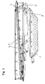
- the boom 3 consists of three elements, namely a fixedly connected to the bridge laying vehicle 1 main body 5, a pivotally mounted on the body pivot body 6 and a pivotally mounted on the pivot body. 6 arranged on the cantilever arm 7 on both sides locking elements 18 are arranged with bolts for locking a bridge element.
- the Figures 2 and 3 show the bridge laying vehicle, which transports two bridge elements 4.1 with a predetermined length X.
- the bridge elements 4.1 can be coupled to a bridge.
- the coupling process is in Fig. 6 shown.
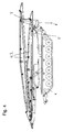
- This in Fig. 2 illustrated bridge laying vehicle 1 has in the front area a mine protection as additional armor, so that the center of gravity of the vehicle 1 relative to the in Fig. 3 shown vehicle without additional armor has moved forward.
- the boom is in Fig. 2 controlled such that the bridge elements 4.1, in particular the upper bridge element 4.1, lie further in the direction of the stern. This allows the center of gravity of the loaded vehicle 1 back to the intended Position be brought so that the stability and safety while driving is guaranteed.
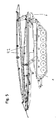
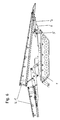
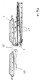
- the boom 3 according to the invention also has the advantage that also bridge elements with a different length can be transported. This is in the FIGS. 4 and 5 shown.
- the bridge elements 4. 2 transported here have a length Y and can be laid individually, ie they do not have to be coupled. Even with the transport of the bridge elements 4.2, it is possible to shift the center of gravity, for example, if the BrükkenverlegeInstitut 1 has an additional armor, as in Fig. 4 shown.
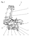
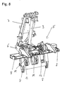
- the boom 3 according to the invention is in the FIGS. 7 and 8th shown in perspective. It has a base frame 5, which can be fastened by four fastening devices 8 on the bridge laying vehicle 1. On the main body 5, a pivot body 6 is pivotally mounted. The pivoting movement of the swivel body 6 relative to the main body 5 is effected via a hydraulic swivel body cylinder 10 as a swivel body adjusting device. On the swivel body 5 of the boom 7 is pivotally mounted. The pivotal movement of the boom 7 relative to the pivot body 6 is effected by a hydraulic Auslegerarmzylinder 9 as boom arm adjustment. The boom cylinder 9 is connected at one end to the boom 7 and at the other end to the swing body 6.
- the swivel body cylinder 10 is connected at one end to the main body 5 and at the other end to the swivel body 6.
- On the main body guide rollers 21 and 22 are also arranged for the support and guidance of a lower bridge element ( Fig. 10 ).
- FIGS. 7 and 8th is the boom 3 in a bridge transport position, the Fig. 3 equivalent. So that in this position, the load of the bridge elements 4.1 is not on the swivel body cylinder 10, 5 two struts 11 are arranged between the swivel body 6 and the base body, which can be locked by means of two locking cylinders 12.
- the struts 11 run as in Fig. 13 shown in a guide slot 13 of the main body. 5
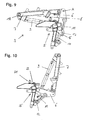
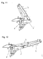
- FIGS. 9 to 12 various positions are shown, which can take the boom 3.
- the positions in Fig. 10 and 11 are taken during a transport or when laying a bridge element.
- the Fig. 12 shown position is when coupling two bridge elements 4.1, as in Fig. 6 shown, taken.
- the Fig. 9 shown position corresponds to the vehicle transport position, which is also in Fig. 1 is shown.
- the swivel body 6 is first pivoted by means of the swivel body cylinder 10 upwards.
- the pivot axis (A) of the cantilever arm moves upward.
- the cantilever arm 7 can be freely pivoted forward in the vehicle travel direction (F). It can assume a substantially horizontal position, specifically the angle of the extension arm 7 to the horizontal in the in Fig. 9 shown position is less than 10 °.
- the boom 3 by two in Fig. 14 illustrated bolt 16 can be fixed.
- the two struts 11 are inserted into a holding device 17, wherein the holding device 17 has bores through which a bolt 16 can be passed.
- the vehicle transport position is thus approached without manual intervention. Only the fixation in their position takes place by the staking out of the two bolts sixteenth
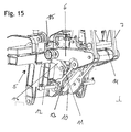
- the positions of the pivot body 6 and the boom 7 are determined by the in Fig. 15 monitored sensors 14 and 15, so that the different positions can be approached by a bridge control without a security risk.
- the Fig. 16 shows the bridge laying vehicle, which is towed together with the charged bridge elements 4.1 by a recovery armor 50 by means of a towing bar, wherein the boom 3 is in the towing position, in which the pivoting body is pivoted particularly high.
Landscapes
- Engineering & Computer Science (AREA)
- Architecture (AREA)
- Civil Engineering (AREA)
- Structural Engineering (AREA)
- Bridges Or Land Bridges (AREA)
- Jib Cranes (AREA)
- Forklifts And Lifting Vehicles (AREA)
Applications Claiming Priority (1)
| Application Number | Priority Date | Filing Date | Title |
|---|---|---|---|
| DE102008007715A DE102008007715A1 (de) | 2008-02-06 | 2008-02-06 | Ausleger eines Brückenverlegefahrzeuges und Verfahren zur Bewegung eines Auslegers in eine Fahrzeugtransportstellung |
Publications (3)
| Publication Number | Publication Date |
|---|---|
| EP2088243A2 true EP2088243A2 (fr) | 2009-08-12 |
| EP2088243A3 EP2088243A3 (fr) | 2012-08-01 |
| EP2088243B1 EP2088243B1 (fr) | 2014-01-15 |
Family
ID=40580917
Family Applications (1)
| Application Number | Title | Priority Date | Filing Date |
|---|---|---|---|
| EP09001225.3A Active EP2088243B1 (fr) | 2008-02-06 | 2009-01-29 | Flèche d'un dispositif de lancement d'un véhicule de pose de pont et procédé de déplacement d'une flèche dans une position de transport de véhicule |
Country Status (4)
| Country | Link |
|---|---|
| US (1) | US8256052B2 (fr) |
| EP (1) | EP2088243B1 (fr) |
| DE (1) | DE102008007715A1 (fr) |
| ES (1) | ES2450367T3 (fr) |
Cited By (1)
| Publication number | Priority date | Publication date | Assignee | Title |
|---|---|---|---|---|
| DE102010061102A1 (de) | 2010-12-08 | 2012-06-14 | Krauss-Maffei Wegmann Gmbh & Co. Kg | Verlegeeinrichtung zur Anordnung an Brückenverlegefahrzeugen und Brückenverlegefahrzeug |
Families Citing this family (2)
| Publication number | Priority date | Publication date | Assignee | Title |
|---|---|---|---|---|
| DE102010017616B4 (de) | 2010-06-28 | 2015-04-02 | Krauss-Maffei Wegmann Gmbh & Co. Kg | Brückenlegegerät und Verfahren zur Verriegelung eines Brückenelements |
| DE102011000901A1 (de) * | 2011-02-23 | 2012-08-23 | Krauss-Maffei Wegmann Gmbh & Co. Kg | Vorrichtung zum Verriegeln zweier Bauelemente und Brückenverlegefahrzeug mit einer Verriegelungsvorrichtung |
Citations (3)
| Publication number | Priority date | Publication date | Assignee | Title |
|---|---|---|---|---|
| DE3891429C1 (de) | 1988-11-12 | 1992-05-14 | Man Gutehoffnungsh Tte Ag | Br}ckenlegepanzer mit Verlegeeinrichtung f}r }bereinanderliegende Br}cken oder Br}ckenabschnitte |
| DE19701650C2 (de) | 1997-01-18 | 2001-08-16 | Man Technologie Gmbh | Verlegeeinrichtung und Verfahren zum Verlegen zerlegbarer Brücken |
| DE102005041493B3 (de) | 2005-09-01 | 2007-04-12 | Rheinmetall Landsysteme Gmbh | Vorrichtung zum Ablegen eines Heckauslegers insbesondere eines Brückenverlegers |
Family Cites Families (13)
| Publication number | Priority date | Publication date | Assignee | Title |
|---|---|---|---|---|
| US3820181A (en) * | 1972-03-29 | 1974-06-28 | Kloeckner Humboldt Deutz Ag | Bridge laying device |
| FR2200856A5 (fr) * | 1972-09-28 | 1974-04-19 | France Etat | |
| DE2403494C2 (de) * | 1974-01-25 | 1982-09-09 | Dr.Ing.H.C. F. Porsche Ag, 7000 Stuttgart | Verlege- und Transportfahrzeug |
| US4510637A (en) * | 1983-03-14 | 1985-04-16 | Lucjan Zlotnicki | Bridge launcher |
| US4602399A (en) * | 1984-05-24 | 1986-07-29 | Harsco Corporation | Bridge transporting and launching trailer and method |
| GB8421616D0 (en) * | 1984-08-24 | 1984-09-26 | Secr Defence | Pickaback bridge spans |
| DE3737681A1 (de) * | 1987-11-06 | 1989-05-18 | Iveco Magirus | Verlegepanzer mit verlegeeinrichtung zum verlegen von brueckenteilen an einer brueckenstelle |
| GB8821298D0 (en) * | 1988-09-12 | 1988-10-12 | Secr Defence | Folding transportable bridge |
| FR2637300B1 (fr) * | 1988-09-30 | 1990-11-16 | France Etat Armement | Engin poseur de ponts |
| FR2678297B3 (fr) * | 1991-06-28 | 1993-10-08 | Peugeot Talbot Espana Sa | Vehicule lance-ponts. |
| DE4127106C2 (de) * | 1991-08-16 | 1994-12-08 | Gutehoffnungshuette Man | Mobiles Brückenlegegerät |
| DE4401768C2 (de) * | 1994-01-24 | 1996-06-13 | Krupp Foerdertechnik Gmbh | An einer Verlegeeinrichtung montierter Antrieb zum Verschieben von Brückenabschnitten |
| DE102007041579B4 (de) * | 2007-09-01 | 2009-07-30 | General Dynamics Santa Bárbara Sistemas GmbH | Anbauvorrichtung zum Transportieren und Verlegen von militärischen Brücken |
-
2008
- 2008-02-06 DE DE102008007715A patent/DE102008007715A1/de not_active Withdrawn
-
2009
- 2009-01-29 EP EP09001225.3A patent/EP2088243B1/fr active Active
- 2009-01-29 ES ES09001225.3T patent/ES2450367T3/es active Active
- 2009-02-03 US US12/364,964 patent/US8256052B2/en not_active Expired - Fee Related
Patent Citations (3)
| Publication number | Priority date | Publication date | Assignee | Title |
|---|---|---|---|---|
| DE3891429C1 (de) | 1988-11-12 | 1992-05-14 | Man Gutehoffnungsh Tte Ag | Br}ckenlegepanzer mit Verlegeeinrichtung f}r }bereinanderliegende Br}cken oder Br}ckenabschnitte |
| DE19701650C2 (de) | 1997-01-18 | 2001-08-16 | Man Technologie Gmbh | Verlegeeinrichtung und Verfahren zum Verlegen zerlegbarer Brücken |
| DE102005041493B3 (de) | 2005-09-01 | 2007-04-12 | Rheinmetall Landsysteme Gmbh | Vorrichtung zum Ablegen eines Heckauslegers insbesondere eines Brückenverlegers |
Cited By (3)
| Publication number | Priority date | Publication date | Assignee | Title |
|---|---|---|---|---|
| DE102010061102A1 (de) | 2010-12-08 | 2012-06-14 | Krauss-Maffei Wegmann Gmbh & Co. Kg | Verlegeeinrichtung zur Anordnung an Brückenverlegefahrzeugen und Brückenverlegefahrzeug |
| WO2012083943A2 (fr) | 2010-12-08 | 2012-06-28 | Krauss-Maffei Wegmann Gmbh & Co. Kg | Dispositif de pose destiné à être agencé sur des véhicules poseurs de pont et véhicule poseur de pont |
| WO2012083943A3 (fr) * | 2010-12-08 | 2012-08-30 | Krauss-Maffei Wegmann Gmbh & Co. Kg | Dispositif de pose destiné à être agencé sur des véhicules poseurs de pont et véhicule poseur de pont |
Also Published As
| Publication number | Publication date |
|---|---|
| ES2450367T3 (es) | 2014-03-24 |
| EP2088243A3 (fr) | 2012-08-01 |
| US20090194499A1 (en) | 2009-08-06 |
| EP2088243B1 (fr) | 2014-01-15 |
| DE102008007715A1 (de) | 2009-09-10 |
| US8256052B2 (en) | 2012-09-04 |
Similar Documents
| Publication | Publication Date | Title |
|---|---|---|
| DE3844743C2 (de) | Schleppfahrzeug zum Manövrieren von Flugzeugen | |
| EP0758973B1 (fr) | Vehicule remorqueur pour man uvrer des aeronefs | |
| DE3131512C2 (de) | Knicklenker mit querverschiebbarem Gegengewicht | |
| DE19701650C2 (de) | Verlegeeinrichtung und Verfahren zum Verlegen zerlegbarer Brücken | |
| DE7529603U (de) | An einer zugmaschine anbringbare materialhandhabungsvorrichtung | |
| DE2430137A1 (de) | Abschleppvorrichtung fuer fahrzeuge | |
| EP2088243B1 (fr) | Flèche d'un dispositif de lancement d'un véhicule de pose de pont et procédé de déplacement d'une flèche dans une position de transport de véhicule | |
| DE102012021613A1 (de) | Schwerlast-Transportfahrzeug zum Transport eines länglichen Objekts | |
| EP3636520B1 (fr) | Dispositif de ballastage et véhicule agricole | |
| EP0551160B1 (fr) | Support d'appareil pour le montage sur véhicules automoteurs, en particulier pour la préparation des pistes de ski | |
| DE3801855A1 (de) | Schleppfahrzeug zum manoevrieren von flugzeugen | |
| EP4086218A1 (fr) | Système et procédé de haubanage pour une flèche télescopique de grue mobile | |
| DE102014008720B4 (de) | Schwerlastfahrzeug mit Staplerfunktion | |
| DE4415405C2 (de) | Schleppfahrzeug zum Manövrieren von Flugzeugen | |
| DE2641807C2 (de) | Fahrzeug zum Transport und Verlegen von Brückenteilen | |
| EP0529507A1 (fr) | Tracteur de piste pour la manutation d'avions | |
| EP4244428B1 (fr) | Véhicule de déplacement de pont | |
| DE8904394U1 (de) | Kran-/Bohrgerätewagen | |
| DE4135653C2 (de) | Abstützvorrichtung für Sonderfahrzeuge, insbesondere für fahrbare Betonpumpe | |
| DE10210818B4 (de) | Haltevorrichtung für Hubschrauber | |
| EP3398903B1 (fr) | Véhicule, outil et procédé de montage en surface de tuyaux | |
| EP4053066A2 (fr) | Dispositif et procédé de montage / démontage d'une flèche de grue mobile | |
| DE941532C (de) | Einrichtung zum Befoerdern und Starten von Luftfahrzeugen | |
| DE3007074A1 (de) | Land- und/oder bauwirtschaftlich nutzbarer schlepper | |
| DES0040294MA (fr) |
Legal Events
| Date | Code | Title | Description |
|---|---|---|---|
| PUAI | Public reference made under article 153(3) epc to a published international application that has entered the european phase |
Free format text: ORIGINAL CODE: 0009012 |
|
| AK | Designated contracting states |
Kind code of ref document: A2 Designated state(s): AT BE BG CH CY CZ DE DK EE ES FI FR GB GR HR HU IE IS IT LI LT LU LV MC MK MT NL NO PL PT RO SE SI SK TR |
|
| AX | Request for extension of the european patent |
Extension state: AL BA RS |
|
| PUAL | Search report despatched |
Free format text: ORIGINAL CODE: 0009013 |
|
| AK | Designated contracting states |
Kind code of ref document: A3 Designated state(s): AT BE BG CH CY CZ DE DK EE ES FI FR GB GR HR HU IE IS IT LI LT LU LV MC MK MT NL NO PL PT RO SE SI SK TR |
|
| AX | Request for extension of the european patent |
Extension state: AL BA RS |
|
| RIC1 | Information provided on ipc code assigned before grant |
Ipc: E01D 15/127 20060101AFI20120628BHEP |
|
| 17P | Request for examination filed |
Effective date: 20130111 |
|
| 17Q | First examination report despatched |
Effective date: 20130313 |
|
| AKX | Designation fees paid |
Designated state(s): AT BE BG CH CY CZ DE DK EE ES FI FR GB GR HR HU IE IS IT LI LT LU LV MC MK MT NL NO PL PT RO SE SI SK TR |
|
| GRAP | Despatch of communication of intention to grant a patent |
Free format text: ORIGINAL CODE: EPIDOSNIGR1 |
|
| INTG | Intention to grant announced |
Effective date: 20131002 |
|
| GRAS | Grant fee paid |
Free format text: ORIGINAL CODE: EPIDOSNIGR3 |
|
| GRAA | (expected) grant |
Free format text: ORIGINAL CODE: 0009210 |
|
| AK | Designated contracting states |
Kind code of ref document: B1 Designated state(s): AT BE BG CH CY CZ DE DK EE ES FI FR GB GR HR HU IE IS IT LI LT LU LV MC MK MT NL NO PL PT RO SE SI SK TR |
|
| REG | Reference to a national code |
Ref country code: GB Ref legal event code: FG4D Free format text: NOT ENGLISH Ref country code: CH Ref legal event code: EP |
|
| REG | Reference to a national code |
Ref country code: CH Ref legal event code: NV Representative=s name: BOHEST AG, CH |
|
| REG | Reference to a national code |
Ref country code: AT Ref legal event code: REF Ref document number: 649911 Country of ref document: AT Kind code of ref document: T Effective date: 20140215 |
|
| REG | Reference to a national code |
Ref country code: IE Ref legal event code: FG4D Free format text: LANGUAGE OF EP DOCUMENT: GERMAN |
|
| REG | Reference to a national code |
Ref country code: DE Ref legal event code: R096 Ref document number: 502009008677 Country of ref document: DE Effective date: 20140227 |
|
| REG | Reference to a national code |
Ref country code: ES Ref legal event code: FG2A Ref document number: 2450367 Country of ref document: ES Kind code of ref document: T3 Effective date: 20140324 |
|
| REG | Reference to a national code |
Ref country code: SE Ref legal event code: TRGR |
|
| REG | Reference to a national code |
Ref country code: NL Ref legal event code: VDEP Effective date: 20140115 |
|
| REG | Reference to a national code |
Ref country code: LT Ref legal event code: MG4D |
|
| BERE | Be: lapsed |
Owner name: KRAUSS-MAFFEI WEGMANN G.M.B.H. & CO. KG Effective date: 20140131 |
|
| PG25 | Lapsed in a contracting state [announced via postgrant information from national office to epo] |
Ref country code: LT Free format text: LAPSE BECAUSE OF FAILURE TO SUBMIT A TRANSLATION OF THE DESCRIPTION OR TO PAY THE FEE WITHIN THE PRESCRIBED TIME-LIMIT Effective date: 20140115 Ref country code: NO Free format text: LAPSE BECAUSE OF FAILURE TO SUBMIT A TRANSLATION OF THE DESCRIPTION OR TO PAY THE FEE WITHIN THE PRESCRIBED TIME-LIMIT Effective date: 20140415 Ref country code: IS Free format text: LAPSE BECAUSE OF FAILURE TO SUBMIT A TRANSLATION OF THE DESCRIPTION OR TO PAY THE FEE WITHIN THE PRESCRIBED TIME-LIMIT Effective date: 20140515 |
|
| REG | Reference to a national code |
Ref country code: CH Ref legal event code: PCAR Free format text: NEW ADDRESS: HOLBEINSTRASSE 36-38, 4051 BASEL (CH) |
|
| PG25 | Lapsed in a contracting state [announced via postgrant information from national office to epo] |
Ref country code: PT Free format text: LAPSE BECAUSE OF FAILURE TO SUBMIT A TRANSLATION OF THE DESCRIPTION OR TO PAY THE FEE WITHIN THE PRESCRIBED TIME-LIMIT Effective date: 20140515 Ref country code: CY Free format text: LAPSE BECAUSE OF FAILURE TO SUBMIT A TRANSLATION OF THE DESCRIPTION OR TO PAY THE FEE WITHIN THE PRESCRIBED TIME-LIMIT Effective date: 20140115 Ref country code: NL Free format text: LAPSE BECAUSE OF FAILURE TO SUBMIT A TRANSLATION OF THE DESCRIPTION OR TO PAY THE FEE WITHIN THE PRESCRIBED TIME-LIMIT Effective date: 20140115 |
|
| PG25 | Lapsed in a contracting state [announced via postgrant information from national office to epo] |
Ref country code: HR Free format text: LAPSE BECAUSE OF FAILURE TO SUBMIT A TRANSLATION OF THE DESCRIPTION OR TO PAY THE FEE WITHIN THE PRESCRIBED TIME-LIMIT Effective date: 20140115 Ref country code: LV Free format text: LAPSE BECAUSE OF FAILURE TO SUBMIT A TRANSLATION OF THE DESCRIPTION OR TO PAY THE FEE WITHIN THE PRESCRIBED TIME-LIMIT Effective date: 20140115 |
|
| REG | Reference to a national code |
Ref country code: DE Ref legal event code: R097 Ref document number: 502009008677 Country of ref document: DE |
|
| PG25 | Lapsed in a contracting state [announced via postgrant information from national office to epo] |
Ref country code: DK Free format text: LAPSE BECAUSE OF FAILURE TO SUBMIT A TRANSLATION OF THE DESCRIPTION OR TO PAY THE FEE WITHIN THE PRESCRIBED TIME-LIMIT Effective date: 20140115 Ref country code: CZ Free format text: LAPSE BECAUSE OF FAILURE TO SUBMIT A TRANSLATION OF THE DESCRIPTION OR TO PAY THE FEE WITHIN THE PRESCRIBED TIME-LIMIT Effective date: 20140115 Ref country code: RO Free format text: LAPSE BECAUSE OF FAILURE TO SUBMIT A TRANSLATION OF THE DESCRIPTION OR TO PAY THE FEE WITHIN THE PRESCRIBED TIME-LIMIT Effective date: 20140115 Ref country code: EE Free format text: LAPSE BECAUSE OF FAILURE TO SUBMIT A TRANSLATION OF THE DESCRIPTION OR TO PAY THE FEE WITHIN THE PRESCRIBED TIME-LIMIT Effective date: 20140115 Ref country code: MC Free format text: LAPSE BECAUSE OF FAILURE TO SUBMIT A TRANSLATION OF THE DESCRIPTION OR TO PAY THE FEE WITHIN THE PRESCRIBED TIME-LIMIT Effective date: 20140115 |
|
| REG | Reference to a national code |
Ref country code: IE Ref legal event code: MM4A |
|
| PLBE | No opposition filed within time limit |
Free format text: ORIGINAL CODE: 0009261 |
|
| STAA | Information on the status of an ep patent application or granted ep patent |
Free format text: STATUS: NO OPPOSITION FILED WITHIN TIME LIMIT |
|
| PG25 | Lapsed in a contracting state [announced via postgrant information from national office to epo] |
Ref country code: PL Free format text: LAPSE BECAUSE OF FAILURE TO SUBMIT A TRANSLATION OF THE DESCRIPTION OR TO PAY THE FEE WITHIN THE PRESCRIBED TIME-LIMIT Effective date: 20140115 Ref country code: SK Free format text: LAPSE BECAUSE OF FAILURE TO SUBMIT A TRANSLATION OF THE DESCRIPTION OR TO PAY THE FEE WITHIN THE PRESCRIBED TIME-LIMIT Effective date: 20140115 |
|
| 26N | No opposition filed |
Effective date: 20141016 |
|
| PG25 | Lapsed in a contracting state [announced via postgrant information from national office to epo] |
Ref country code: IE Free format text: LAPSE BECAUSE OF NON-PAYMENT OF DUE FEES Effective date: 20140129 Ref country code: BE Free format text: LAPSE BECAUSE OF NON-PAYMENT OF DUE FEES Effective date: 20140131 |
|
| REG | Reference to a national code |
Ref country code: DE Ref legal event code: R097 Ref document number: 502009008677 Country of ref document: DE Effective date: 20141016 |
|
| REG | Reference to a national code |
Ref country code: AT Ref legal event code: MM01 Ref document number: 649911 Country of ref document: AT Kind code of ref document: T Effective date: 20140129 |
|
| PG25 | Lapsed in a contracting state [announced via postgrant information from national office to epo] |
Ref country code: SI Free format text: LAPSE BECAUSE OF FAILURE TO SUBMIT A TRANSLATION OF THE DESCRIPTION OR TO PAY THE FEE WITHIN THE PRESCRIBED TIME-LIMIT Effective date: 20140115 Ref country code: AT Free format text: LAPSE BECAUSE OF NON-PAYMENT OF DUE FEES Effective date: 20140129 |
|
| REG | Reference to a national code |
Ref country code: FR Ref legal event code: PLFP Year of fee payment: 8 |
|
| PG25 | Lapsed in a contracting state [announced via postgrant information from national office to epo] |
Ref country code: MT Free format text: LAPSE BECAUSE OF FAILURE TO SUBMIT A TRANSLATION OF THE DESCRIPTION OR TO PAY THE FEE WITHIN THE PRESCRIBED TIME-LIMIT Effective date: 20140115 |
|
| PG25 | Lapsed in a contracting state [announced via postgrant information from national office to epo] |
Ref country code: BG Free format text: LAPSE BECAUSE OF FAILURE TO SUBMIT A TRANSLATION OF THE DESCRIPTION OR TO PAY THE FEE WITHIN THE PRESCRIBED TIME-LIMIT Effective date: 20140115 |
|
| PG25 | Lapsed in a contracting state [announced via postgrant information from national office to epo] |
Ref country code: GR Free format text: LAPSE BECAUSE OF FAILURE TO SUBMIT A TRANSLATION OF THE DESCRIPTION OR TO PAY THE FEE WITHIN THE PRESCRIBED TIME-LIMIT Effective date: 20140416 |
|
| PG25 | Lapsed in a contracting state [announced via postgrant information from national office to epo] |
Ref country code: LU Free format text: LAPSE BECAUSE OF NON-PAYMENT OF DUE FEES Effective date: 20140129 Ref country code: HU Free format text: LAPSE BECAUSE OF FAILURE TO SUBMIT A TRANSLATION OF THE DESCRIPTION OR TO PAY THE FEE WITHIN THE PRESCRIBED TIME-LIMIT; INVALID AB INITIO Effective date: 20090129 Ref country code: TR Free format text: LAPSE BECAUSE OF FAILURE TO SUBMIT A TRANSLATION OF THE DESCRIPTION OR TO PAY THE FEE WITHIN THE PRESCRIBED TIME-LIMIT Effective date: 20140115 |
|
| REG | Reference to a national code |
Ref country code: FR Ref legal event code: PLFP Year of fee payment: 9 |
|
| REG | Reference to a national code |
Ref country code: FR Ref legal event code: PLFP Year of fee payment: 10 |
|
| PGFP | Annual fee paid to national office [announced via postgrant information from national office to epo] |
Ref country code: ES Payment date: 20180220 Year of fee payment: 10 Ref country code: CH Payment date: 20180125 Year of fee payment: 10 Ref country code: GB Payment date: 20180125 Year of fee payment: 10 Ref country code: FI Payment date: 20180119 Year of fee payment: 10 |
|
| PGFP | Annual fee paid to national office [announced via postgrant information from national office to epo] |
Ref country code: SE Payment date: 20180125 Year of fee payment: 10 Ref country code: FR Payment date: 20180124 Year of fee payment: 10 Ref country code: IT Payment date: 20180126 Year of fee payment: 10 |
|
| PG25 | Lapsed in a contracting state [announced via postgrant information from national office to epo] |
Ref country code: MK Free format text: LAPSE BECAUSE OF FAILURE TO SUBMIT A TRANSLATION OF THE DESCRIPTION OR TO PAY THE FEE WITHIN THE PRESCRIBED TIME-LIMIT Effective date: 20140115 |
|
| REG | Reference to a national code |
Ref country code: CH Ref legal event code: PL |
|
| GBPC | Gb: european patent ceased through non-payment of renewal fee |
Effective date: 20190129 |
|
| PG25 | Lapsed in a contracting state [announced via postgrant information from national office to epo] |
Ref country code: FR Free format text: LAPSE BECAUSE OF NON-PAYMENT OF DUE FEES Effective date: 20190131 Ref country code: SE Free format text: LAPSE BECAUSE OF NON-PAYMENT OF DUE FEES Effective date: 20190130 Ref country code: FI Free format text: LAPSE BECAUSE OF NON-PAYMENT OF DUE FEES Effective date: 20190129 |
|
| PG25 | Lapsed in a contracting state [announced via postgrant information from national office to epo] |
Ref country code: GB Free format text: LAPSE BECAUSE OF NON-PAYMENT OF DUE FEES Effective date: 20190129 Ref country code: LI Free format text: LAPSE BECAUSE OF NON-PAYMENT OF DUE FEES Effective date: 20190131 Ref country code: CH Free format text: LAPSE BECAUSE OF NON-PAYMENT OF DUE FEES Effective date: 20190131 |
|
| PG25 | Lapsed in a contracting state [announced via postgrant information from national office to epo] |
Ref country code: IT Free format text: LAPSE BECAUSE OF NON-PAYMENT OF DUE FEES Effective date: 20190129 |
|
| REG | Reference to a national code |
Ref country code: ES Ref legal event code: FD2A Effective date: 20200310 |
|
| PG25 | Lapsed in a contracting state [announced via postgrant information from national office to epo] |
Ref country code: ES Free format text: LAPSE BECAUSE OF NON-PAYMENT OF DUE FEES Effective date: 20190130 |
|
| P01 | Opt-out of the competence of the unified patent court (upc) registered |
Effective date: 20230517 |
|
| REG | Reference to a national code |
Ref country code: DE Ref legal event code: R081 Ref document number: 502009008677 Country of ref document: DE Owner name: KNDS DEUTSCHLAND GMBH & CO. KG, DE Free format text: FORMER OWNER: KRAUSS-MAFFEI WEGMANN GMBH & CO. KG, 80997 MUENCHEN, DE |
|
| PGFP | Annual fee paid to national office [announced via postgrant information from national office to epo] |
Ref country code: DE Payment date: 20260131 Year of fee payment: 18 |