EP2088299A2 - Echangeur thermique destiné au refroidissement de l'air de suralimentation, procédé destiné à la fabrication d'un échangeur thermique destiné au refroidissement de l'air de suralimentation - Google Patents
Echangeur thermique destiné au refroidissement de l'air de suralimentation, procédé destiné à la fabrication d'un échangeur thermique destiné au refroidissement de l'air de suralimentation Download PDFInfo
- Publication number
- EP2088299A2 EP2088299A2 EP08021963A EP08021963A EP2088299A2 EP 2088299 A2 EP2088299 A2 EP 2088299A2 EP 08021963 A EP08021963 A EP 08021963A EP 08021963 A EP08021963 A EP 08021963A EP 2088299 A2 EP2088299 A2 EP 2088299A2
- Authority
- EP
- European Patent Office
- Prior art keywords
- heat exchanger
- turbulence
- disc
- charge air
- coolant
- Prior art date
- Legal status (The legal status is an assumption and is not a legal conclusion. Google has not performed a legal analysis and makes no representation as to the accuracy of the status listed.)
- Granted
Links
Images


Classifications
-
- F—MECHANICAL ENGINEERING; LIGHTING; HEATING; WEAPONS; BLASTING
- F02—COMBUSTION ENGINES; HOT-GAS OR COMBUSTION-PRODUCT ENGINE PLANTS
- F02B—INTERNAL-COMBUSTION PISTON ENGINES; COMBUSTION ENGINES IN GENERAL
- F02B29/00—Engines characterised by provision for charging or scavenging not provided for in groups F02B25/00, F02B27/00 or F02B33/00 - F02B39/00; Details thereof
- F02B29/04—Cooling of air intake supply
- F02B29/045—Constructional details of the heat exchangers, e.g. pipes, plates, ribs, insulation, materials, or manufacturing and assembly
- F02B29/0462—Liquid cooled heat exchangers
-
- F—MECHANICAL ENGINEERING; LIGHTING; HEATING; WEAPONS; BLASTING
- F28—HEAT EXCHANGE IN GENERAL
- F28D—HEAT-EXCHANGE APPARATUS, NOT PROVIDED FOR IN ANOTHER SUBCLASS, IN WHICH THE HEAT-EXCHANGE MEDIA DO NOT COME INTO DIRECT CONTACT
- F28D7/00—Heat-exchange apparatus having stationary tubular conduit assemblies for both heat-exchange media, the media being in contact with different sides of a conduit wall
- F28D7/16—Heat-exchange apparatus having stationary tubular conduit assemblies for both heat-exchange media, the media being in contact with different sides of a conduit wall the conduits being arranged in parallel spaced relation
- F28D7/1684—Heat-exchange apparatus having stationary tubular conduit assemblies for both heat-exchange media, the media being in contact with different sides of a conduit wall the conduits being arranged in parallel spaced relation the conduits having a non-circular cross-section
-
- F—MECHANICAL ENGINEERING; LIGHTING; HEATING; WEAPONS; BLASTING
- F28—HEAT EXCHANGE IN GENERAL
- F28D—HEAT-EXCHANGE APPARATUS, NOT PROVIDED FOR IN ANOTHER SUBCLASS, IN WHICH THE HEAT-EXCHANGE MEDIA DO NOT COME INTO DIRECT CONTACT
- F28D9/00—Heat-exchange apparatus having stationary plate-like or laminated conduit assemblies for both heat-exchange media, the media being in contact with different sides of a conduit wall
- F28D9/0031—Heat-exchange apparatus having stationary plate-like or laminated conduit assemblies for both heat-exchange media, the media being in contact with different sides of a conduit wall the conduits for one heat-exchange medium being formed by paired plates touching each other
- F28D9/0043—Heat-exchange apparatus having stationary plate-like or laminated conduit assemblies for both heat-exchange media, the media being in contact with different sides of a conduit wall the conduits for one heat-exchange medium being formed by paired plates touching each other the plates having openings therein for circulation of at least one heat-exchange medium from one conduit to another
-
- F—MECHANICAL ENGINEERING; LIGHTING; HEATING; WEAPONS; BLASTING
- F28—HEAT EXCHANGE IN GENERAL
- F28F—DETAILS OF HEAT-EXCHANGE AND HEAT-TRANSFER APPARATUS, OF GENERAL APPLICATION
- F28F9/00—Casings; Header boxes; Auxiliary supports for elements; Auxiliary members within casings
- F28F9/02—Header boxes; End plates
- F28F9/026—Header boxes; End plates with static flow control means, e.g. with means for uniformly distributing heat exchange media into conduits
- F28F9/028—Header boxes; End plates with static flow control means, e.g. with means for uniformly distributing heat exchange media into conduits by using inserts for modifying the pattern of flow inside the header box, e.g. by using flow restrictors or permeable bodies or blocks with channels
-
- F—MECHANICAL ENGINEERING; LIGHTING; HEATING; WEAPONS; BLASTING
- F28—HEAT EXCHANGE IN GENERAL
- F28D—HEAT-EXCHANGE APPARATUS, NOT PROVIDED FOR IN ANOTHER SUBCLASS, IN WHICH THE HEAT-EXCHANGE MEDIA DO NOT COME INTO DIRECT CONTACT
- F28D1/00—Heat-exchange apparatus having stationary conduit assemblies for one heat-exchange medium only, the media being in contact with different sides of the conduit wall, in which the other heat-exchange medium is a large body of fluid, e.g. domestic or motor car radiators
- F28D1/02—Heat-exchange apparatus having stationary conduit assemblies for one heat-exchange medium only, the media being in contact with different sides of the conduit wall, in which the other heat-exchange medium is a large body of fluid, e.g. domestic or motor car radiators with heat-exchange conduits immersed in the body of fluid
- F28D1/03—Heat-exchange apparatus having stationary conduit assemblies for one heat-exchange medium only, the media being in contact with different sides of the conduit wall, in which the other heat-exchange medium is a large body of fluid, e.g. domestic or motor car radiators with heat-exchange conduits immersed in the body of fluid with plate-like or laminated conduits
- F28D1/0308—Heat-exchange apparatus having stationary conduit assemblies for one heat-exchange medium only, the media being in contact with different sides of the conduit wall, in which the other heat-exchange medium is a large body of fluid, e.g. domestic or motor car radiators with heat-exchange conduits immersed in the body of fluid with plate-like or laminated conduits the conduits being formed by paired plates touching each other
- F28D1/0325—Heat-exchange apparatus having stationary conduit assemblies for one heat-exchange medium only, the media being in contact with different sides of the conduit wall, in which the other heat-exchange medium is a large body of fluid, e.g. domestic or motor car radiators with heat-exchange conduits immersed in the body of fluid with plate-like or laminated conduits the conduits being formed by paired plates touching each other the plates having lateral openings therein for circulation of the heat-exchange medium from one conduit to another
-
- F—MECHANICAL ENGINEERING; LIGHTING; HEATING; WEAPONS; BLASTING
- F28—HEAT EXCHANGE IN GENERAL
- F28F—DETAILS OF HEAT-EXCHANGE AND HEAT-TRANSFER APPARATUS, OF GENERAL APPLICATION
- F28F9/00—Casings; Header boxes; Auxiliary supports for elements; Auxiliary members within casings
- F28F9/02—Header boxes; End plates
- F28F9/026—Header boxes; End plates with static flow control means, e.g. with means for uniformly distributing heat exchange media into conduits
- F28F9/0282—Header boxes; End plates with static flow control means, e.g. with means for uniformly distributing heat exchange media into conduits by varying the geometry of conduit ends, e.g. by using inserts or attachments for modifying the pattern of flow at the conduit inlet or outlet
-
- Y—GENERAL TAGGING OF NEW TECHNOLOGICAL DEVELOPMENTS; GENERAL TAGGING OF CROSS-SECTIONAL TECHNOLOGIES SPANNING OVER SEVERAL SECTIONS OF THE IPC; TECHNICAL SUBJECTS COVERED BY FORMER USPC CROSS-REFERENCE ART COLLECTIONS [XRACs] AND DIGESTS
- Y02—TECHNOLOGIES OR APPLICATIONS FOR MITIGATION OR ADAPTATION AGAINST CLIMATE CHANGE
- Y02T—CLIMATE CHANGE MITIGATION TECHNOLOGIES RELATED TO TRANSPORTATION
- Y02T10/00—Road transport of goods or passengers
- Y02T10/10—Internal combustion engine [ICE] based vehicles
- Y02T10/12—Improving ICE efficiencies
Definitions
- the present invention relates to a heat exchanger for charge air cooling for an internal combustion engine of a motor vehicle and to a method for producing a heat exchanger according to one of claims 1 to 11.
- Direct charge air cooling cools the charge air directly from the ambient air.
- the charge air is cooled by a coolant, in particular a coolant containing cooling water.
- the cooling liquid is in turn cooled by the ambient air.
- a heat exchanger in particular a charge air cooler with the coolant flowed through slices known. Furthermore, intermediate spaces are provided which are flowed through by the charge air and filled with corrugated ribs, wherein the package formed by the discs is inserted into a through-flow of the charge air housing.
- the plate heat exchanger is an oil cooler made up of stacked disks.
- a heat exchanger with turbulence inserts known.
- the turbulence inserts are used within a heat exchanger to fluidize a fluid passing therethrough.
- the turbulence insert has rods for deflecting the fluid flowing through the turbulence insert.
- the object is to improve the flow through the coolant-carrying flow channels and to increase the flow rate.
- the rigidity of the discs and the pairs of discs of the heat exchanger stack increases and at the same time reduces the pressure drop of the coolant in the coolant channel and the heat transfer surface can be increased.
- the required installation space is to be reduced and the integration of the heat exchanger into other components improved.
- a heat exchanger for charge air cooling for an internal combustion engine of a motor vehicle is proposed with at least one disk, wherein two adjacent disks form at least one disk pair and at least one first flow channel for throughflow for at least one coolant. Between two adjacent disk pairs, a second flow channel is at least partially formed to flow through for charge air.
- the pairs of discs form a heat exchanger block.
- At least in regions, at least one turbulence-inducing insert is arranged in the at least one first flow channel between the adjacent disks.
- the turbulence-inducing insert is formed with at least one jib-like end section for inflow or outflow improvement of the coolant into or out of the at least one first flow channel and for increasing the strength of the heat exchanger block.
- a pair of discs is in particular formed of a first disc and a disc placed on the first disc and tilted essentially by 180 °.
- the pairs of discs are stacked on top of one another and form a heat exchanger stack.
- a first flow channel for the flow through at least one coolant, in particular a coolant flow channel is formed.
- a second flow channel for the passage of charge air, in particular a charge air flow channel is formed.
- the discs and / or the pairs of discs are positively, in particular by folding, crimping, etc. and / or cohesively, in particular by soldering, welding, gluing, etc. interconnected and form a heat exchanger block.
- At least one turbulence-inducing insert is arranged in the at least one first flow channel, in particular in the first flow channels, between the adjacent disks, in particular a pair of disks.
- the at least one turbulence-generating insert has at least one end portion region formed like a weir for the inflow or outflow improvement of the coolant into or out of the at least one first flow channel.
- the at least one turbulence-generating insert serves to increase the strength of the heat exchanger block, in particular at least one pair of discs, in particular the discs.
- the end portion region, in particular of the at least one turbulence-inducing insert projects at least partially into an overhang length into at least one feed channel for supplying coolant to the disk pairs and / or into at least one discharge channel for discharging the coolant from the at least one disk pair.
- the at least one turbulence-inducing insert connected to at least one disc in particular form-fitting, in particular by crimping, folding, flanging, etc., and / or materially, in particular by soldering, welding, gluing, etc., is connected , It can further be provided that the at least one turbulence-inducing insert is integrally formed with the at least one disk, or formed with the disk pairs, or in which at least one disk or the disks of at least one pair of disks or disk pairs is imprinted or introduced.
- the at least one turbulence-generating insert in particular the turbulence-generating deposits, at least partially formed like a labyrinth and / or have substantially burgzinnenförmige characteristics.
- the heat transfer performance can be particularly advantageously improved and at the same time the pressure drop of the coolant can be reduced.
- the characteristics have at least one Ausgargungsbreite, wherein the Ausgargungsbreite increases in at least one flow direction of the coolant at least partially and / or remains the same and / or decreases.
- the at least one turbulence-inducing insert thus has a particularly low profile, for example in the inflow region of the coolant, whereby the turbulence effect is increased particularly advantageously and the heat transfer is increased in a particularly advantageous manner.
- the Auslessnesssbach in particular particularly advantageous larger, so that the pressure drop is lower.
- the characteristics on at least one expression length increases and / or remains the same and / or decreases in one direction, the direction having an angle ⁇ with a flow direction of the coolant.
- the expression, in particular in the flow direction of the charge air initially has a lower expression length than seen in the flow direction of the charge air in a rear region.
- the pressure drop of the charge air in one area - seen in the charge air flow direction - can be reduced further back
- At least one disc in particular the discs, at least one cup-shaped impression, in particular at least two cup-like impressions on.
- the at least one cup-like form, in particular the two cup-like characteristics, at the same time advantageously space adjacent pairs of panes or adjacent panes.
- At least one second turbulence-generating element in particular two turbulence-generating elements, are provided in the at least one second flow channel, in particular in the second flow channels, for improving the heat transfer between charge air and coolant.
- the space can be particularly advantageously reduced and the heat transfer between charge air and coolant, in particular cooling liquid, are optimally designed optimally.
- At least one housing receives the heat exchanger block at least regionally, in particular completely, and / or at least one housing is formed at least in sections as a suction tube section of a suction tube for an internal combustion engine and / or at least as a compressor housing section of a compressor housing for an internal combustion engine.
- the space can be reduced particularly advantageous in which the heat exchanger can be integrated into another component particularly advantageous.
- the at least one flow direction of the coolant, in particular of the cooling liquid forms an angle ⁇ with the at least one flow direction of the charge air.
- the heat transfer performance between charge air and coolant, in particular cooling liquid particularly advantageously increased and the at least one inlet and / or outlet port for the charge air or for the coolant, in particular the coolant, particularly advantageous according to the design specifications in the engine compartment of a motor vehicle to be ordered.
- the heat exchanger is used as a charge air cooler.
- a method for producing a heat exchanger according to the invention wherein the at least one disc, in particular the discs, at least one disc pair, in particular the disc pairs, by means of a forming manufacturing process, in particular by means of stamping, embossing, pressing, etc. are produced. Furthermore, disk pairs with at least two disks each are formed from the disks, with at least one first turbulence-inducing insert being particularly advantageously introduced between the two disks of a disk pair.
- the discs, the pairs of discs and the at least one first turbulence-generating insert, in particular the turbulence-generating deposits are materially connected, in particular by soldering, welding, gluing, etc., and / or positively, in particular by folding, crimping, crimping, etc., interconnected.
- the intercooler is designed as an I-flow cooler.
- charge air flows into the heat exchanger on one side of the heat exchanger and out of the heat exchanger on another, in particular opposite, side.
- coolant in particular cooling liquid, flows into the heat exchanger on one side and out of the heat exchanger on another, in particular opposite, side.
- the heat exchanger in particular the intercooler, designed as a U-flow heat exchanger.
- the coolant in particular the cooling liquid flows in a U-shape, d. H. flows into the heat exchanger on one side, flows through it, is deflected in a U-shape, flows back in the opposite direction and flows out again on the same side out of the heat exchanger, into which the coolant has flowed into the heat exchanger.
- the heat exchanger is designed as an exhaust gas cooler, wherein the medium to be cooled is no charge air, but exhaust gas, in particular recirculated exhaust gas is.
- the heat exchanger is an oil cooler for cooling transmission oil of a transmission of an internal combustion engine.
- the heat exchanger is a condenser or an evaporator or a gas cooler for an air conditioning system of a motor vehicle.
- the heat exchanger is a charge air cooler and / or an exhaust gas cooler and / or a coolant radiator and / or a two- or multi-stage intercooler for multi-stage cooling of charge air.
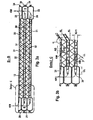
- FIG. 1 shows an isometric sectional view of a heat exchanger.
- the heat exchanger 1 is designed in particular as a charge air cooler.
- the heat exchanger 1 has at least one housing 2 and a cover 3 and a heat exchanger block 4.
- the housing 2 is formed of metal such as aluminum or gray cast iron. In another embodiment, the housing 2 is made of a plastic or of ceramic or of a fiber composite material.
- the housing 2 is produced by means of a primary shaping production method such as, for example, casting, in particular injection molding or gravity die casting. Further, the housing is machined in a further embodiment by means of an abrasive manufacturing process such as milling, turning or drilling, in particular machined.
- a primary shaping production method such as, for example, casting, in particular injection molding or gravity die casting.
- the housing is machined in a further embodiment by means of an abrasive manufacturing process such as milling, turning or drilling, in particular machined.
- the housing has an unspecified inlet connection for charge air, which essentially has a connection flange ring, which tapers and enters into the housing 2 or, in a further exemplary embodiment, is formed integrally with the housing 2.
- the housing 2 has an unspecified cavity.
- the cavity is particularly adapted to the geometry of the heat exchanger block 4.
- the unspecified cavity has a substantially cuboidal shape, wherein substantially at the smallest parallelepiped surfaces, which are arranged in particular opposite one another and to which in each case substantially a semi-cylindrical body connects. This rectangular space with each subsequent semi-cylindrical space elements is used in particular for receiving the heat exchanger block. 4
- the housing 2 has at least one fastening element, in particular two or more fastening elements 13 for fastening the housing.
- a fastening element 13 essentially has an unspecified opening, for example for insertion of a screw or a bolt.
- the at least one fastening element 13, in particular the fastening elements 13, are formed integrally with the housing 2 in a further exemplary embodiment or, in another exemplary embodiment, are connected to the housing 2.
- the heat exchanger block 4 has a plurality of disk pairs 11. In the region of the semicylindrical formation of the heat exchanger block 4, a feed channel 8, which is likewise essentially semicylindrical, or an essentially cylindrical discharge channel 9 is provided on the opposite side.
- the housing 2 is closed with a lid 3.
- the cover 3 has a coolant inlet connection 5 and / or a coolant outlet connection 6.
- the lid 3 is formed of a metal such as aluminum or steel or stainless steel. In another embodiment, the cover 3 is made of plastic or of ceramic or of a fiber composite material.
- the lid 3 After introduction of the heat exchanger block 4 in the housing 2, the lid 3 is placed on the housing 2 and closes this form-fitting, in particular by crimping, folding, flanging, and / or cohesively by soldering, welding, gluing, etc.
- the housing 2 also has at least one charge air outlet 10 for discharging the cooled charge air.
- the charge air outlet 10 is substantially funnel-like, as well as the charge air inlet nozzle 7, formed.
- coolant flows into the heat exchanger, in particular into the charge air cooler.
- the coolant KM is a water-containing coolant or a water-containing coolant. In another embodiment, however, it may also be a viscous liquid, such as oil.
- the coolant enters into the feed channel 8 and via the feed channel 8 in the first flow channels, flows through the heat exchanger 1 and flows into the discharge channel 9. From the discharge channel 9, the coolant KM flows through the coolant outlet 6 from the heat exchanger 1, in particular from the intercooler , out.
- the gas at the outlet nozzle 10, in particular the charge air a higher temperature than at the inlet nozzle 7, in particular as at the charge air inlet nozzle.
- the charge air is heated, for example.
- the heat transfer from the charge air to be cooled to the disk pairs 11 and thus to the coolant KM is improved. In particular, this increases the heat-transferring area.
- FIG. 2 shows a sectional view AA through the heat exchanger 1.
- the same features are provided with the same reference numerals as in the previous figures.
- a disk pair 11 is formed by a first disk 20 and a second disk 21.
- the first disc 20 and the second disc 21 are formed substantially the same.
- the first disc 20 is tilted substantially 180 ° with respect to the second disc 21.
- the first disc 20 and the second disc 22 are substantially configured such that the first disc 20 essentially forms an associated cover to the second disc 21, essentially forms the associated pot, wherein in the illustrated embodiment, the lid and the associated pot in Essentially the same.
- the first disc 20 is formed differently than the second disc 21.
- FIG. 3a shows a sectional view BB through the heat exchanger 1, wherein the FIG. 3b the detail C of the sectional view BB represents. Identical features are provided with the same reference numerals as in the previous figures.
- Essentially tongue-shaped, in particular substantially semicircular, unspecified end regions adjoin the two ends at this central region, which is not described in any more detail.
- These tongue-shaped end portions are formed as a substantially annular, cup-shaped expression.
- the substantially annular cup-shaped expression 33 encloses a substantially semicircular opening.
- the cup-shaped expression is substantially triangular and / or square or polygonal shape or at least partially elliptical or circular formed or as a combination of the aforementioned forms.
- the discs 20, 21 of a disc pair 11 each have an edge 34 which is formed substantially circumferentially around the disc. In particular, at this edge region, the adjacent discs 20 and 21, which form a disc pair, with each other form-fitting manner, in particular by folding, crimping, flanging, and / or cohesively, for example by soldering, welding, gluing, etc. connected.
- the discs 20, 21 are usually made of sheet metal, such as aluminum sheet or other metallic sheet such as steel or stainless steel by a forming and / or separating manufacturing process.
- the sheets which form the disks 21 and 20, respectively, are solder-plated on one or both sides. In another embodiment, the sheets which form the disks 20, 21 are not solder plated.
- a plurality of disk pairs, each formed by a first disk 20 and a second disk 21, are pre-cassetted and in particular stacked one on top of the other. It is in a pair of discs, d. H. between a first disc 20 and a second disc 21, a first turbulence-inducing insert 30 is introduced.
- the pairs of discs are stacked on top of each other, wherein between the disc pairs, in particular in the region of the second flow channel 32, a second turbulence-generating insert 12 is introduced.
- the second turbulence-generating insert 12 is formed substantially as a corrugated fin.
- the turbulence-generating insert 12 is essentially formed of a thin metal sheet, in particular aluminum sheet, with stamped gills.
- the second turbulence-generating insert 12 is essentially accordion-shaped and is solder-plated on one or both sides. In another embodiment, the turbulence-inducing insert 12 is not solder plated. When cohesively joining the turbulence-generating insert 12 is at least partially connected to at least one disc 21, 20 or at least one pair of discs 11. In another embodiment, the turbulence-generating insert 12 is formed burzzinnenförmig and / or wavy.
- first turbulence-generating deposits 30 are arranged in the at least one first flow channel 31, in particular in the first flow channels 31, first turbulence-generating deposits 30 are arranged.
- the first turbulence-generating inserts 30 are essentially formed from a metallic sheet, such as aluminum or copper or stainless steel, or from another metal or another thermally conductive material.
- the first turbulence-generating inserts 30 are usually formed by forming, such as pressing, embossing, etc., so that they have a substantially burg interior shape. In another embodiment, they may be accordion-shaped. In a further embodiment, they may be formed substantially wave-shaped.
- the first turbulence-generating deposits may be solder-plated on one side and / or on both sides.
- the turbulence inlays have a substantially curved edge in cross section, which is substantially rectangular and / or triangular and / or polygonal or at least partially wavy.
- the burgrabe-shaped profile has substantially U-shaped regions, the U-shaped regions being designed substantially as a rectangular U, ie the U has substantially two parallel opposite sides, which are essentially designed as stretches.
- the unspecified end portions of the track are connected by a further substantially straight-shaped track, wherein the connecting track with the two other routes substantially forms an angle of 90 °.
- the connecting route has the characteristic width AB.
- the Ausgargungsbreite AB is substantially parallel to the coolant flow direction KM.
- the first turbulence-inducing insert 30 is also essentially of a burr-shaped design.
- the first turbulence-generating insert 30 likewise has a profile which is composed of substantially polygonal U-elements which alternate in such a way that they are arranged in the shape of burgers, in particular substantially in the shape of battlements.
- the connecting route has the expression length AL.
- the first turbulence-generating element 30 is designed in such a way that all distances, in particular extent widths AB, are equal over the entire range.
- the sections, in particular the Ausgargungsbreiten AB from Zuzhoukanal Scheme 8 are not formed larger or white larger values than in the inner region, d. H. in a region in the middle of the turbulence-generating insert 30.
- the expression width AB decreases further.
- the opposite case is provided, according to which the expression width AB initially has larger values in the feed channel region 8 and assumes smaller values AB in the direction of the middle and further direction of the discharge channel region 9.
- the first turbulence-generating insert 30 can be designed such that the expression width AB decreases continuously or increases continuously in another embodiment, or in another embodiment increases or decreases degressive or progressive.
- the expression width AB continuously has a specific value in a first region and another value in an adjoining region which has greater or less or, in another embodiment, equal to or corresponds to the preceding expression value AB.
- the expression width AB can assume alternating larger values and again small values. All that has been said about the expression width AB also applies analogously to the expression length AL of the first turbulence-generating insert 30.
- the first turbulence-generating insert 30 is substantially in an end portion region 35, at least partially in the feed channel. 8 and / or is arranged in the discharge channel 9, has a protrusion length ÜL. In the region of the projection length ÜL, the first turbulence-inducing insert projects at least in sections into the feed channel 8 and / or into the discharge channel 9. Due to the formation of the end section region 35, which is essentially jib-shaped, coolant can flow into the first flow channel 31 in a particularly advantageous manner or flow out of the first flow channel 9 into the discharge channel 9. In the end section region 35, the first turbulence-generating element is particularly advantageously formed v-shaped or u-channel-shaped. In this way, a particularly advantageous flow of the first flow channel 31, in particular of the first flow channels 31 out of the feed channel 8 or a particularly advantageous outflow into the discharge channel 9 takes place.
- the first turbulence-generating elements 30 and / or the second turbulence-generating elements 12 stiffen the heat exchanger block 4 in a particularly advantageous manner, in particular the first disks 20 and the second disks 21 or the disk pairs 11, so that they have grown to the pulsation of the charge air flowing through and the consequent permanent load are. In this way, the durability of the heat exchanger is particularly advantageous increased.
- the overlap length ÜL takes values between 0 mm and 15 mm, in particular values between 0 mm and 12 mm, in particular values between 0 mm and 10 mm, in particular values between 0 mm and 8 mm, in particular values between 0 mm and 7 mm, in particular values between 0 mm and 6, 5 mm, in particular values between 0 mm and 4.5 mm, in particular values between 0 mm and 3.25 mm, in particular values between 0 mm and 2 mm.
- the charge air to be cooled flows in the direction LL through the heat exchanger 1 or through the heat exchanger block 4.
- the flow direction of the coolant is designated KM and the direction of the charge air is LL.
- the coolant direction KM and the charge air flow direction LL have an angle ⁇ , wherein the angle ⁇ values between 10 ° and 90 °, in particular between 35 ° and 90 °, in particular between 45 ° and 90 °, in particular between 50 ° and 90 °, in particular between 60 ° and 90 °, in particular between 70 ° and 90 °.
- the angle ⁇ assumes the value 90 °.
- the expression width AB and / or the expression length AL takes values between 0.01 mm and 8 mm, in particular values between 0.01 mm and 7 mm, in particular values between 0.01 mm and 5 mm, in particular between 0.01 mm and 3 mm, in particular values between 0.1 mm and 3 mm.
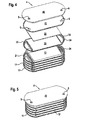
- FIG. 4 shows an exploded view of the heat exchanger block 4 during FIG. 5 an isometric view of the heat exchanger block 4 of the heat exchanger 1 represents. Identical features are provided with the same reference numerals.
- FIG. 4 shows an alternative embodiment, wherein the lid 3 made FIG. 1 is formed essentially of a first cover plate 40 and a second cover plate 41. In another embodiment, only a first cover plate 40 is provided. In a further embodiment, the first cover disk 40 and the second cover disk 41 are integrally formed.
- the first cover plate 40 and / or the second cover plate 41 in this case have at least one opening which is substantially circular, in another embodiment rectangular or elliptical, for the coolant inlet 5 and an opening substantially the same for the coolant outlet 6.
- the first cover plate 40 and the second cover plate 41 are substantially materially connected by welding, soldering, gluing, etc. and / or positively connected by crimping or folding.
Landscapes
- Engineering & Computer Science (AREA)
- Physics & Mathematics (AREA)
- Thermal Sciences (AREA)
- Mechanical Engineering (AREA)
- General Engineering & Computer Science (AREA)
- Chemical & Material Sciences (AREA)
- Combustion & Propulsion (AREA)
- Heat-Exchange Devices With Radiators And Conduit Assemblies (AREA)
Applications Claiming Priority (1)
| Application Number | Priority Date | Filing Date | Title |
|---|---|---|---|
| DE102008007916A DE102008007916A1 (de) | 2008-02-06 | 2008-02-06 | Wärmetauscher zur Ladeluftkühlung, Verfahren zur Herstellung eines Wärmetauschers zur Ladeluftkühlung |
Publications (3)
| Publication Number | Publication Date |
|---|---|
| EP2088299A2 true EP2088299A2 (fr) | 2009-08-12 |
| EP2088299A3 EP2088299A3 (fr) | 2014-04-02 |
| EP2088299B1 EP2088299B1 (fr) | 2017-03-29 |
Family
ID=40568198
Family Applications (1)
| Application Number | Title | Priority Date | Filing Date |
|---|---|---|---|
| EP08021963.7A Not-in-force EP2088299B1 (fr) | 2008-02-06 | 2008-12-18 | Echangeur thermique destiné au refroidissement de l'air de suralimentation, procédé destiné à la fabrication d'un échangeur thermique destiné au refroidissement de l'air de suralimentation |
Country Status (2)
| Country | Link |
|---|---|
| EP (1) | EP2088299B1 (fr) |
| DE (1) | DE102008007916A1 (fr) |
Cited By (5)
| Publication number | Priority date | Publication date | Assignee | Title |
|---|---|---|---|---|
| GB2488997A (en) * | 2011-03-14 | 2012-09-19 | O Gen Uk Ltd | Engine with Turbocharger and Intake Cleaning Features |
| US20150129183A1 (en) * | 2012-04-28 | 2015-05-14 | Modine Manufacturing Company | Heat exchanger having a cooler block and production method |
| WO2015121038A1 (fr) * | 2014-02-11 | 2015-08-20 | MAHLE Behr GmbH & Co. KG | Refroidisseur d'air de suralimentation pour système d'air frais d'un moteur à combustion interne |
| EP3101263A1 (fr) * | 2015-06-03 | 2016-12-07 | Hörnlein Umformtechnik GmbH | Tuyau de distributeur de carburant et composant de vehicule automobile |
| DE102019106643A1 (de) * | 2019-03-15 | 2020-09-17 | Schaufler Tooling GmbH & Co. KG | Wassermantelkern |
Families Citing this family (4)
| Publication number | Priority date | Publication date | Assignee | Title |
|---|---|---|---|---|
| DE102011012577A1 (de) * | 2011-02-26 | 2012-08-30 | Volkswagen Ag | Wärmeaustauschvorrichtung |
| FR2977307B1 (fr) | 2011-06-30 | 2013-08-09 | Valeo Systemes Thermiques | Boitier d'echangeur a plaques empilees et echangeur comprenant un tel boitier |
| DE102015217092A1 (de) * | 2015-09-07 | 2017-03-09 | Mahle International Gmbh | Brennkraftmaschine |
| DE102020116223A1 (de) | 2020-06-19 | 2021-12-23 | Montaplast Gesellschaft mit beschränkter Haftung | Ladeluftkühler |
Citations (4)
| Publication number | Priority date | Publication date | Assignee | Title |
|---|---|---|---|---|
| EP0623798A2 (fr) | 1993-05-05 | 1994-11-09 | Behr GmbH & Co. | Echangeur de chaleur à plaques, en particulier refroidisseur d'huile |
| DE19547185A1 (de) | 1995-12-16 | 1997-06-19 | Behr Gmbh & Co | Wärmeübertrager |
| DE19654365A1 (de) | 1996-12-24 | 1998-06-25 | Behr Gmbh & Co | Plattenwärmeübertrager |
| DE19902504A1 (de) | 1999-01-22 | 2000-08-10 | Behr Gmbh & Co | Wärmeübertrager, insbesondere Ladeluftkühler |
Family Cites Families (9)
| Publication number | Priority date | Publication date | Assignee | Title |
|---|---|---|---|---|
| US4815532A (en) * | 1986-02-28 | 1989-03-28 | Showa Aluminum Kabushiki Kaisha | Stack type heat exchanger |
| JPH04177094A (ja) * | 1990-11-13 | 1992-06-24 | Sanden Corp | 積層型熱交換器 |
| DE4403144C3 (de) * | 1994-02-02 | 2002-05-29 | Laengerer & Reich Gmbh & Co | Plattenwärmeaustauscher |
| FR2737287B1 (fr) * | 1995-07-25 | 1997-09-12 | Valeo Thermique Moteur Sa | Echangeur de chaleur a boite collectrice sous forme d'un empilement |
| US6341649B1 (en) * | 2001-02-12 | 2002-01-29 | Delphi Technologies, Inc. | Aluminum plate oil cooler |
| US20030024696A1 (en) * | 2001-08-03 | 2003-02-06 | Ingersoll-Rand Energy Systems Corporation | Counterflow plate-fin heat exchanger with extended header fin |
| FR2856747B1 (fr) * | 2003-06-25 | 2005-09-23 | Valeo Thermique Moteur Sa | Module de refroidissement de l'air de suralimentation et des gaz d'echappement recircules d'un moteur a combustion interne de vehicule automobile. |
| US7108054B2 (en) * | 2003-09-11 | 2006-09-19 | Honeywell International, Inc. | Heat exchanger |
| DE102005036601A1 (de) * | 2004-07-30 | 2006-03-23 | Behr Gmbh & Co. Kg | Einstückige Turbulenzeinlage |
-
2008
- 2008-02-06 DE DE102008007916A patent/DE102008007916A1/de not_active Ceased
- 2008-12-18 EP EP08021963.7A patent/EP2088299B1/fr not_active Not-in-force
Patent Citations (4)
| Publication number | Priority date | Publication date | Assignee | Title |
|---|---|---|---|---|
| EP0623798A2 (fr) | 1993-05-05 | 1994-11-09 | Behr GmbH & Co. | Echangeur de chaleur à plaques, en particulier refroidisseur d'huile |
| DE19547185A1 (de) | 1995-12-16 | 1997-06-19 | Behr Gmbh & Co | Wärmeübertrager |
| DE19654365A1 (de) | 1996-12-24 | 1998-06-25 | Behr Gmbh & Co | Plattenwärmeübertrager |
| DE19902504A1 (de) | 1999-01-22 | 2000-08-10 | Behr Gmbh & Co | Wärmeübertrager, insbesondere Ladeluftkühler |
Cited By (6)
| Publication number | Priority date | Publication date | Assignee | Title |
|---|---|---|---|---|
| GB2488997A (en) * | 2011-03-14 | 2012-09-19 | O Gen Uk Ltd | Engine with Turbocharger and Intake Cleaning Features |
| US20150129183A1 (en) * | 2012-04-28 | 2015-05-14 | Modine Manufacturing Company | Heat exchanger having a cooler block and production method |
| WO2015121038A1 (fr) * | 2014-02-11 | 2015-08-20 | MAHLE Behr GmbH & Co. KG | Refroidisseur d'air de suralimentation pour système d'air frais d'un moteur à combustion interne |
| US10180291B2 (en) | 2014-02-11 | 2019-01-15 | MAHLE Behr GmbH & Co. KG | Charge air cooler for a fresh air system of an internal combustion engine |
| EP3101263A1 (fr) * | 2015-06-03 | 2016-12-07 | Hörnlein Umformtechnik GmbH | Tuyau de distributeur de carburant et composant de vehicule automobile |
| DE102019106643A1 (de) * | 2019-03-15 | 2020-09-17 | Schaufler Tooling GmbH & Co. KG | Wassermantelkern |
Also Published As
| Publication number | Publication date |
|---|---|
| DE102008007916A1 (de) | 2009-08-13 |
| EP2088299B1 (fr) | 2017-03-29 |
| EP2088299A3 (fr) | 2014-04-02 |
Similar Documents
| Publication | Publication Date | Title |
|---|---|---|
| EP2088299B1 (fr) | Echangeur thermique destiné au refroidissement de l'air de suralimentation, procédé destiné à la fabrication d'un échangeur thermique destiné au refroidissement de l'air de suralimentation | |
| EP1985953B1 (fr) | Echangeur thermique, en particulier destiné au refroidissement des gaz d'échappement, procédé d'utilisation d'un tel échangeur et système comprenant un refroidisseur EGR | |
| EP1911946B1 (fr) | Dispositif de refroidissement de l'air de suralimentation pour un moteur à combustion interne, système doté d'un dispositif de refroidissement de l'air de suralimentation | |
| EP1901020B1 (fr) | Echangeur thermique à plaques superposées destiné au refroidissement d'air de suralimentation | |
| EP2066992A2 (fr) | Échangeur thermique destiné à un moteur à combustion interne | |
| EP2655828A1 (fr) | Tube aspirant avec refroidisseur d'air de suralimentation intégré | |
| EP1999423A2 (fr) | Échangeur thermique pour véhicule automobile | |
| DE102007038894A1 (de) | Stapel-/Stangen-Plattenladeluftkühler welcher Einlass-und Auslass-Behälter umfasst | |
| EP1941224A1 (fr) | Echangeur thermique | |
| EP2652285A1 (fr) | Dispositif de refroidissement de l'air de suralimentation, système de conditionnement de l'air de suralimentation et module d'aspiration pour un moteur à combustion interne | |
| EP1586845B1 (fr) | Echangeur de chaleur pour un gas d'echappement | |
| EP1895258A2 (fr) | Dispositif d'échange de chaleur | |
| EP1864005A1 (fr) | Echangeur thermique pour gaz d'echappement, notamment refroidisseur de gaz d'echappement pour le recyclage des gaz d'echappement dans les vehicules a moteur | |
| WO2008113540A2 (fr) | Canal d'écoulement, échangeur de chaleur, système de recyclage des gaz d'échappement, système d'apport d'air de suralimentation et utilisation d'un échangeur de chaleur | |
| EP3039372B1 (fr) | Échangeur de chaleur | |
| DE102006049106A1 (de) | Wärmetauscher | |
| EP2029883A1 (fr) | Échangeur de chaleur | |
| WO2019072853A1 (fr) | Échangeur de chaleur de gaz d'échappement | |
| EP1570223B1 (fr) | Echangeur thermique | |
| EP1845242A2 (fr) | Échangeur de chaleur pour refroidissement d'air d'admission pour véhicule et système | |
| DE102014212906A1 (de) | Ladeluftkühler mit einem Plattenwärmetauscher | |
| DE102009039833A1 (de) | Wärmeübertragungsvorrichtung sowie Verfahren zur Herstellung einer derartigen Wärmeübertragungsvorrichtung | |
| DE102006013868A1 (de) | Abgaswärmeübertrager, insbesondere Abgaskühler für eine Abgasrückführung in Kraftfahrzeugen | |
| DE102005036045B4 (de) | Kühlvorrichtung für Verbrennungskraftmaschinen | |
| DE102005045098A1 (de) | Kühlvorrichtung für eine Verbrennungskraftmaschine |
Legal Events
| Date | Code | Title | Description |
|---|---|---|---|
| PUAI | Public reference made under article 153(3) epc to a published international application that has entered the european phase |
Free format text: ORIGINAL CODE: 0009012 |
|
| AK | Designated contracting states |
Kind code of ref document: A2 Designated state(s): AT BE BG CH CY CZ DE DK EE ES FI FR GB GR HR HU IE IS IT LI LT LU LV MC MT NL NO PL PT RO SE SI SK TR |
|
| AX | Request for extension of the european patent |
Extension state: AL BA MK RS |
|
| PUAL | Search report despatched |
Free format text: ORIGINAL CODE: 0009013 |
|
| AK | Designated contracting states |
Kind code of ref document: A3 Designated state(s): AT BE BG CH CY CZ DE DK EE ES FI FR GB GR HR HU IE IS IT LI LT LU LV MC MT NL NO PL PT RO SE SI SK TR |
|
| AX | Request for extension of the european patent |
Extension state: AL BA MK RS |
|
| RIC1 | Information provided on ipc code assigned before grant |
Ipc: F02B 29/04 20060101AFI20140221BHEP Ipc: F28F 9/02 20060101ALI20140221BHEP Ipc: F28D 9/00 20060101ALI20140221BHEP Ipc: F28D 7/16 20060101ALI20140221BHEP |
|
| 17P | Request for examination filed |
Effective date: 20141002 |
|
| RBV | Designated contracting states (corrected) |
Designated state(s): AT BE BG CH CY CZ DE DK EE ES FI FR GB GR HR HU IE IS IT LI LT LU LV MC MT NL NO PL PT RO SE SI SK TR |
|
| AKX | Designation fees paid |
Designated state(s): AT BE BG CH CY CZ DE DK EE ES FI FR GB GR HR HU IE IS IT LI LT LU LV MC MT NL NO PL PT RO SE SI SK TR |
|
| AXX | Extension fees paid |
Extension state: RS Extension state: MK Extension state: BA Extension state: AL |
|
| RAP1 | Party data changed (applicant data changed or rights of an application transferred) |
Owner name: MAHLE BEHR GMBH & CO. KG |
|
| GRAP | Despatch of communication of intention to grant a patent |
Free format text: ORIGINAL CODE: EPIDOSNIGR1 |
|
| INTG | Intention to grant announced |
Effective date: 20161005 |
|
| GRAJ | Information related to disapproval of communication of intention to grant by the applicant or resumption of examination proceedings by the epo deleted |
Free format text: ORIGINAL CODE: EPIDOSDIGR1 |
|
| GRAR | Information related to intention to grant a patent recorded |
Free format text: ORIGINAL CODE: EPIDOSNIGR71 |
|
| GRAS | Grant fee paid |
Free format text: ORIGINAL CODE: EPIDOSNIGR3 |
|
| GRAA | (expected) grant |
Free format text: ORIGINAL CODE: 0009210 |
|
| INTC | Intention to grant announced (deleted) | ||
| RIN1 | Information on inventor provided before grant (corrected) |
Inventor name: WEGNER, JUERGEN Inventor name: HENDRIX, DANIEL |
|
| INTG | Intention to grant announced |
Effective date: 20170216 |
|
| AK | Designated contracting states |
Kind code of ref document: B1 Designated state(s): AT BE BG CH CY CZ DE DK EE ES FI FR GB GR HR HU IE IS IT LI LT LU LV MC MT NL NO PL PT RO SE SI SK TR |
|
| REG | Reference to a national code |
Ref country code: GB Ref legal event code: FG4D Free format text: NOT ENGLISH |
|
| REG | Reference to a national code |
Ref country code: CH Ref legal event code: EP |
|
| REG | Reference to a national code |
Ref country code: AT Ref legal event code: REF Ref document number: 880007 Country of ref document: AT Kind code of ref document: T Effective date: 20170415 |
|
| REG | Reference to a national code |
Ref country code: IE Ref legal event code: FG4D Free format text: LANGUAGE OF EP DOCUMENT: GERMAN |
|
| REG | Reference to a national code |
Ref country code: DE Ref legal event code: R096 Ref document number: 502008015156 Country of ref document: DE |
|
| PG25 | Lapsed in a contracting state [announced via postgrant information from national office to epo] |
Ref country code: LT Free format text: LAPSE BECAUSE OF FAILURE TO SUBMIT A TRANSLATION OF THE DESCRIPTION OR TO PAY THE FEE WITHIN THE PRESCRIBED TIME-LIMIT Effective date: 20170329 Ref country code: GR Free format text: LAPSE BECAUSE OF FAILURE TO SUBMIT A TRANSLATION OF THE DESCRIPTION OR TO PAY THE FEE WITHIN THE PRESCRIBED TIME-LIMIT Effective date: 20170630 Ref country code: FI Free format text: LAPSE BECAUSE OF FAILURE TO SUBMIT A TRANSLATION OF THE DESCRIPTION OR TO PAY THE FEE WITHIN THE PRESCRIBED TIME-LIMIT Effective date: 20170329 Ref country code: NO Free format text: LAPSE BECAUSE OF FAILURE TO SUBMIT A TRANSLATION OF THE DESCRIPTION OR TO PAY THE FEE WITHIN THE PRESCRIBED TIME-LIMIT Effective date: 20170629 Ref country code: HR Free format text: LAPSE BECAUSE OF FAILURE TO SUBMIT A TRANSLATION OF THE DESCRIPTION OR TO PAY THE FEE WITHIN THE PRESCRIBED TIME-LIMIT Effective date: 20170329 |
|
| REG | Reference to a national code |
Ref country code: NL Ref legal event code: MP Effective date: 20170329 |
|
| PG25 | Lapsed in a contracting state [announced via postgrant information from national office to epo] |
Ref country code: LV Free format text: LAPSE BECAUSE OF FAILURE TO SUBMIT A TRANSLATION OF THE DESCRIPTION OR TO PAY THE FEE WITHIN THE PRESCRIBED TIME-LIMIT Effective date: 20170329 Ref country code: SE Free format text: LAPSE BECAUSE OF FAILURE TO SUBMIT A TRANSLATION OF THE DESCRIPTION OR TO PAY THE FEE WITHIN THE PRESCRIBED TIME-LIMIT Effective date: 20170329 Ref country code: BG Free format text: LAPSE BECAUSE OF FAILURE TO SUBMIT A TRANSLATION OF THE DESCRIPTION OR TO PAY THE FEE WITHIN THE PRESCRIBED TIME-LIMIT Effective date: 20170629 |
|
| PG25 | Lapsed in a contracting state [announced via postgrant information from national office to epo] |
Ref country code: NL Free format text: LAPSE BECAUSE OF FAILURE TO SUBMIT A TRANSLATION OF THE DESCRIPTION OR TO PAY THE FEE WITHIN THE PRESCRIBED TIME-LIMIT Effective date: 20170329 |
|
| PG25 | Lapsed in a contracting state [announced via postgrant information from national office to epo] |
Ref country code: ES Free format text: LAPSE BECAUSE OF FAILURE TO SUBMIT A TRANSLATION OF THE DESCRIPTION OR TO PAY THE FEE WITHIN THE PRESCRIBED TIME-LIMIT Effective date: 20170329 Ref country code: RO Free format text: LAPSE BECAUSE OF FAILURE TO SUBMIT A TRANSLATION OF THE DESCRIPTION OR TO PAY THE FEE WITHIN THE PRESCRIBED TIME-LIMIT Effective date: 20170329 Ref country code: CZ Free format text: LAPSE BECAUSE OF FAILURE TO SUBMIT A TRANSLATION OF THE DESCRIPTION OR TO PAY THE FEE WITHIN THE PRESCRIBED TIME-LIMIT Effective date: 20170329 Ref country code: EE Free format text: LAPSE BECAUSE OF FAILURE TO SUBMIT A TRANSLATION OF THE DESCRIPTION OR TO PAY THE FEE WITHIN THE PRESCRIBED TIME-LIMIT Effective date: 20170329 Ref country code: IT Free format text: LAPSE BECAUSE OF FAILURE TO SUBMIT A TRANSLATION OF THE DESCRIPTION OR TO PAY THE FEE WITHIN THE PRESCRIBED TIME-LIMIT Effective date: 20170329 Ref country code: SK Free format text: LAPSE BECAUSE OF FAILURE TO SUBMIT A TRANSLATION OF THE DESCRIPTION OR TO PAY THE FEE WITHIN THE PRESCRIBED TIME-LIMIT Effective date: 20170329 |
|
| PG25 | Lapsed in a contracting state [announced via postgrant information from national office to epo] |
Ref country code: PL Free format text: LAPSE BECAUSE OF FAILURE TO SUBMIT A TRANSLATION OF THE DESCRIPTION OR TO PAY THE FEE WITHIN THE PRESCRIBED TIME-LIMIT Effective date: 20170329 Ref country code: PT Free format text: LAPSE BECAUSE OF FAILURE TO SUBMIT A TRANSLATION OF THE DESCRIPTION OR TO PAY THE FEE WITHIN THE PRESCRIBED TIME-LIMIT Effective date: 20170731 Ref country code: IS Free format text: LAPSE BECAUSE OF FAILURE TO SUBMIT A TRANSLATION OF THE DESCRIPTION OR TO PAY THE FEE WITHIN THE PRESCRIBED TIME-LIMIT Effective date: 20170729 |
|
| REG | Reference to a national code |
Ref country code: DE Ref legal event code: R097 Ref document number: 502008015156 Country of ref document: DE |
|
| PG25 | Lapsed in a contracting state [announced via postgrant information from national office to epo] |
Ref country code: DK Free format text: LAPSE BECAUSE OF FAILURE TO SUBMIT A TRANSLATION OF THE DESCRIPTION OR TO PAY THE FEE WITHIN THE PRESCRIBED TIME-LIMIT Effective date: 20170329 |
|
| PLBE | No opposition filed within time limit |
Free format text: ORIGINAL CODE: 0009261 |
|
| STAA | Information on the status of an ep patent application or granted ep patent |
Free format text: STATUS: NO OPPOSITION FILED WITHIN TIME LIMIT |
|
| 26N | No opposition filed |
Effective date: 20180103 |
|
| PG25 | Lapsed in a contracting state [announced via postgrant information from national office to epo] |
Ref country code: SI Free format text: LAPSE BECAUSE OF FAILURE TO SUBMIT A TRANSLATION OF THE DESCRIPTION OR TO PAY THE FEE WITHIN THE PRESCRIBED TIME-LIMIT Effective date: 20170329 |
|
| REG | Reference to a national code |
Ref country code: CH Ref legal event code: PL |
|
| GBPC | Gb: european patent ceased through non-payment of renewal fee |
Effective date: 20171218 |
|
| REG | Reference to a national code |
Ref country code: IE Ref legal event code: MM4A |
|
| PG25 | Lapsed in a contracting state [announced via postgrant information from national office to epo] |
Ref country code: MT Free format text: LAPSE BECAUSE OF FAILURE TO SUBMIT A TRANSLATION OF THE DESCRIPTION OR TO PAY THE FEE WITHIN THE PRESCRIBED TIME-LIMIT Effective date: 20170329 Ref country code: LU Free format text: LAPSE BECAUSE OF NON-PAYMENT OF DUE FEES Effective date: 20171218 |
|
| REG | Reference to a national code |
Ref country code: FR Ref legal event code: ST Effective date: 20180831 |
|
| REG | Reference to a national code |
Ref country code: BE Ref legal event code: MM Effective date: 20171231 |
|
| PG25 | Lapsed in a contracting state [announced via postgrant information from national office to epo] |
Ref country code: FR Free format text: LAPSE BECAUSE OF NON-PAYMENT OF DUE FEES Effective date: 20180102 Ref country code: IE Free format text: LAPSE BECAUSE OF NON-PAYMENT OF DUE FEES Effective date: 20171218 |
|
| PG25 | Lapsed in a contracting state [announced via postgrant information from national office to epo] |
Ref country code: GB Free format text: LAPSE BECAUSE OF NON-PAYMENT OF DUE FEES Effective date: 20171218 Ref country code: BE Free format text: LAPSE BECAUSE OF NON-PAYMENT OF DUE FEES Effective date: 20171231 Ref country code: LI Free format text: LAPSE BECAUSE OF NON-PAYMENT OF DUE FEES Effective date: 20171231 Ref country code: CH Free format text: LAPSE BECAUSE OF NON-PAYMENT OF DUE FEES Effective date: 20171231 |
|
| REG | Reference to a national code |
Ref country code: AT Ref legal event code: MM01 Ref document number: 880007 Country of ref document: AT Kind code of ref document: T Effective date: 20171218 |
|
| PG25 | Lapsed in a contracting state [announced via postgrant information from national office to epo] |
Ref country code: AT Free format text: LAPSE BECAUSE OF NON-PAYMENT OF DUE FEES Effective date: 20171218 |
|
| PG25 | Lapsed in a contracting state [announced via postgrant information from national office to epo] |
Ref country code: MC Free format text: LAPSE BECAUSE OF FAILURE TO SUBMIT A TRANSLATION OF THE DESCRIPTION OR TO PAY THE FEE WITHIN THE PRESCRIBED TIME-LIMIT Effective date: 20170329 Ref country code: HU Free format text: LAPSE BECAUSE OF FAILURE TO SUBMIT A TRANSLATION OF THE DESCRIPTION OR TO PAY THE FEE WITHIN THE PRESCRIBED TIME-LIMIT; INVALID AB INITIO Effective date: 20081218 |
|
| PG25 | Lapsed in a contracting state [announced via postgrant information from national office to epo] |
Ref country code: CY Free format text: LAPSE BECAUSE OF NON-PAYMENT OF DUE FEES Effective date: 20170329 |
|
| PG25 | Lapsed in a contracting state [announced via postgrant information from national office to epo] |
Ref country code: TR Free format text: LAPSE BECAUSE OF FAILURE TO SUBMIT A TRANSLATION OF THE DESCRIPTION OR TO PAY THE FEE WITHIN THE PRESCRIBED TIME-LIMIT Effective date: 20170329 |
|
| PGFP | Annual fee paid to national office [announced via postgrant information from national office to epo] |
Ref country code: DE Payment date: 20230220 Year of fee payment: 15 |
|
| REG | Reference to a national code |
Ref country code: DE Ref legal event code: R119 Ref document number: 502008015156 Country of ref document: DE |
|
| PG25 | Lapsed in a contracting state [announced via postgrant information from national office to epo] |
Ref country code: DE Free format text: LAPSE BECAUSE OF NON-PAYMENT OF DUE FEES Effective date: 20240702 |
|
| PG25 | Lapsed in a contracting state [announced via postgrant information from national office to epo] |
Ref country code: DE Free format text: LAPSE BECAUSE OF NON-PAYMENT OF DUE FEES Effective date: 20240702 |