EP2088335A2 - Connecteur de profilés - Google Patents
Connecteur de profilés Download PDFInfo
- Publication number
- EP2088335A2 EP2088335A2 EP09001590A EP09001590A EP2088335A2 EP 2088335 A2 EP2088335 A2 EP 2088335A2 EP 09001590 A EP09001590 A EP 09001590A EP 09001590 A EP09001590 A EP 09001590A EP 2088335 A2 EP2088335 A2 EP 2088335A2
- Authority
- EP
- European Patent Office
- Prior art keywords
- profile
- profile connector
- projections
- base
- connector
- Prior art date
- Legal status (The legal status is an assumption and is not a legal conclusion. Google has not performed a legal analysis and makes no representation as to the accuracy of the status listed.)
- Granted
Links
Images




Classifications
-
- F—MECHANICAL ENGINEERING; LIGHTING; HEATING; WEAPONS; BLASTING
- F16—ENGINEERING ELEMENTS AND UNITS; GENERAL MEASURES FOR PRODUCING AND MAINTAINING EFFECTIVE FUNCTIONING OF MACHINES OR INSTALLATIONS; THERMAL INSULATION IN GENERAL
- F16B—DEVICES FOR FASTENING OR SECURING CONSTRUCTIONAL ELEMENTS OR MACHINE PARTS TOGETHER, e.g. NAILS, BOLTS, CIRCLIPS, CLAMPS, CLIPS OR WEDGES; JOINTS OR JOINTING
- F16B3/00—Key-type connections; Keys
-
- E—FIXED CONSTRUCTIONS
- E06—DOORS, WINDOWS, SHUTTERS, OR ROLLER BLINDS IN GENERAL; LADDERS
- E06B—FIXED OR MOVABLE CLOSURES FOR OPENINGS IN BUILDINGS, VEHICLES, FENCES OR LIKE ENCLOSURES IN GENERAL, e.g. DOORS, WINDOWS, BLINDS, GATES
- E06B3/00—Window sashes, door leaves, or like elements for closing wall or like openings; Layout of fixed or moving closures, e.g. windows in wall or like openings; Features of rigidly-mounted outer frames relating to the mounting of wing frames
- E06B3/96—Corner joints or edge joints for windows, doors, or the like frames or wings
- E06B3/964—Corner joints or edge joints for windows, doors, or the like frames or wings using separate connection pieces, e.g. T-connection pieces
- E06B3/968—Corner joints or edge joints for windows, doors, or the like frames or wings using separate connection pieces, e.g. T-connection pieces characterised by the way the connecting pieces are fixed in or on the frame members
- E06B3/972—Corner joints or edge joints for windows, doors, or the like frames or wings using separate connection pieces, e.g. T-connection pieces characterised by the way the connecting pieces are fixed in or on the frame members by increasing the cross-section of the connecting pieces, e.g. by expanding the connecting pieces with wedges
-
- F—MECHANICAL ENGINEERING; LIGHTING; HEATING; WEAPONS; BLASTING
- F16—ENGINEERING ELEMENTS AND UNITS; GENERAL MEASURES FOR PRODUCING AND MAINTAINING EFFECTIVE FUNCTIONING OF MACHINES OR INSTALLATIONS; THERMAL INSULATION IN GENERAL
- F16B—DEVICES FOR FASTENING OR SECURING CONSTRUCTIONAL ELEMENTS OR MACHINE PARTS TOGETHER, e.g. NAILS, BOLTS, CIRCLIPS, CLAMPS, CLIPS OR WEDGES; JOINTS OR JOINTING
- F16B7/00—Connections of rods or tubes, e.g. of non-circular section, mutually, including resilient connections
- F16B7/04—Clamping or clipping connections
-
- F—MECHANICAL ENGINEERING; LIGHTING; HEATING; WEAPONS; BLASTING
- F16—ENGINEERING ELEMENTS AND UNITS; GENERAL MEASURES FOR PRODUCING AND MAINTAINING EFFECTIVE FUNCTIONING OF MACHINES OR INSTALLATIONS; THERMAL INSULATION IN GENERAL
- F16B—DEVICES FOR FASTENING OR SECURING CONSTRUCTIONAL ELEMENTS OR MACHINE PARTS TOGETHER, e.g. NAILS, BOLTS, CIRCLIPS, CLAMPS, CLIPS OR WEDGES; JOINTS OR JOINTING
- F16B7/00—Connections of rods or tubes, e.g. of non-circular section, mutually, including resilient connections
- F16B7/18—Connections of rods or tubes, e.g. of non-circular section, mutually, including resilient connections using screw-thread elements
-
- E—FIXED CONSTRUCTIONS
- E06—DOORS, WINDOWS, SHUTTERS, OR ROLLER BLINDS IN GENERAL; LADDERS
- E06B—FIXED OR MOVABLE CLOSURES FOR OPENINGS IN BUILDINGS, VEHICLES, FENCES OR LIKE ENCLOSURES IN GENERAL, e.g. DOORS, WINDOWS, BLINDS, GATES
- E06B3/00—Window sashes, door leaves, or like elements for closing wall or like openings; Layout of fixed or moving closures, e.g. windows in wall or like openings; Features of rigidly-mounted outer frames relating to the mounting of wing frames
- E06B3/96—Corner joints or edge joints for windows, doors, or the like frames or wings
- E06B3/964—Corner joints or edge joints for windows, doors, or the like frames or wings using separate connection pieces, e.g. T-connection pieces
- E06B3/9642—Butt type joints with at least one frame member cut off square; T-shape joints
-
- E—FIXED CONSTRUCTIONS
- E06—DOORS, WINDOWS, SHUTTERS, OR ROLLER BLINDS IN GENERAL; LADDERS
- E06B—FIXED OR MOVABLE CLOSURES FOR OPENINGS IN BUILDINGS, VEHICLES, FENCES OR LIKE ENCLOSURES IN GENERAL, e.g. DOORS, WINDOWS, BLINDS, GATES
- E06B3/00—Window sashes, door leaves, or like elements for closing wall or like openings; Layout of fixed or moving closures, e.g. windows in wall or like openings; Features of rigidly-mounted outer frames relating to the mounting of wing frames
- E06B3/96—Corner joints or edge joints for windows, doors, or the like frames or wings
- E06B3/964—Corner joints or edge joints for windows, doors, or the like frames or wings using separate connection pieces, e.g. T-connection pieces
- E06B3/9645—Mitre joints
Definitions
- the invention relates to a connector for profiles, in particular of frame wings.
- U1 is a profile connector in the form of a sliding block known which has two mutually perpendicular legs, which are inserted into a respective profile.
- the two profiles to be joined together are chamfered at their facing end faces by 45 °, so that they include a right angle in the assembled state. This means that the profiles and the groove stones must be worked so precisely that the two profiles are flush with each other in the assembled state.
- When mounting the two profiles must be pushed gradually on the sliding block and precisely moved to each other. This requires an extremely precise positioning of both the profiles and the groove stone.
- the object of the invention is to provide a profile connector that allows easy assembly of profiles to be joined together and is simple in construction.
- An inventive profile connector has a base and at least two elastically deformable projections.
- the two projections are attached to the base or depart from this and extend in Essentially in the same direction.
- the two elastic projections make it possible to insert the profile connector in a profile. Due to the elasticity of the projections, it is possible that the profile connector braced when inserted into the profile with this.
- the profile connector according to the invention additionally has passage openings in sections from which no protrusion extends.
- the through openings extend parallel to the extension direction of the projections. Ie. the projections and the through openings extend in substantially the same direction.
- the through holes allow attachment of other parts to the profile connector. In particular, it is possible ceremonystecken another profile on the base of the profile connector and screwed to the through holes of the profile connector.
- the screws are bolted through the through openings with the one profile.
- the two, to be joined together profiles are mounted, whereby a very simple and quick installation is provided. This has particular advantages in the assembly of profiles to a frame, for example, door or window sashes.
- At least one of the projections of the profile connector may have a passage opening which extends parallel to the extension direction of this projection. This makes it possible, for example, to screw a screw into it, which widens the projection. This can be achieved in a simple manner, an (additional) distortion of this projection in the first profile.
- a pin instead of the screw, a pin may also be driven in the form of a nail.
- each projection provided with a passage opening has at least one slot which extends parallel to the extension direction of the passage opening.
- This slot facilitates expansion of this projection.
- the projection may have at one or more points, seen in cross-section, thinner areas as predetermined breaking points. When writing in a screw or the like, these areas break, so that in each case a slot is formed.
- At least one of the through openings also has an internal thread. This makes it possible, for example, to screw screws with a metric thread into the respective passage opening.
- Figure 1A shows a profile connector 10 according to a first embodiment of the invention in various views.
- Left in Figure 1A is a front view of the profile connector 10 is shown.
- At the top center of the profile connector 10 along a section line A - A is left in Figure 1A whereas on the right in Figure 1A the profile connector 10 along a section line B - B left in Figure 1A is shown.
- the profile connector 10 is shown from above.
- FIG. 1B shows the profile connector 10 in different perspective views.
- the profile connector 10 comprises a base 11, which is preferably block-shaped. On one side of the base 11, projections 12, 12 are formed, which are substantially parallel to each other and have a predetermined distance.
- the projections 12, 12 are provided to be inserted into a gap of a first profile 40, which is formed by means of a wall portion 41 b of a base 41 a and an inner wall portion 41 d of the first profile 40 (see. FIG. 4A ).
- the projections 12, 12 are preferably shaped so that they jam in the respective gap. In the simplest case, this takes place in that the projections 12, 12 have transverse dimensions or have such a distance from one another, which are or are each larger than the respective inner dimensions of the respective intermediate space.
- the projections 12, 12 are elastic.
- the profile connector 10 has a projection 13, which is also integrally formed on one side of the base 11.
- the projections 12, 13 have in cross-section preferably a non-circular inner contour, so that the profile connector 10 is received against rotation when inserted into a profile in this.
- the projection 13 between the projections 12, 12 is arranged at a distance therefrom.
- the projection 13 is formed on the same side of the base 11, on which the projections 12, 12 are formed, and extends substantially parallel to the projections 12, 12.
- the projection 13 is at an insertion of the profile connector 10 in the first profile 40 inserted in a gap which is formed by means of inner wall portions 41 d, 41 d and the base 41 a.
- the projection 13 may be analogous to the projections 12, 12 jammed in this space with the first profile 40.
- the projection 13 has at least one slot 13b, which preferably extends along an overall length of the projection 13.
- the projection 13 also has centrally a through opening 13a, which, seen in cross section, adjoins the slot 13b. Ie. the slot 13b and the through hole 13a are connected to each other.
- the passage opening 13a is used to screw a screw, not shown.
- the profile connector 10 Due to the projections 12, 13 of the profile connector 10 is thus against rotation in the first profile 40 and preferably taken out safe, the profile connector 10 enters into a firm connection with the first profile 40. Profile connector 10 and first profile 40 thus form a fastening part for a second profile 50.
- the passage opening 13a also extends through the base 11 therethrough. This makes it possible to screw a screw from one side of the base 11, which faces away from the projections 12, 13. On this side facing away from the base 11, the through hole 13a preferably has a larger diameter than in the region of the projection 13. This makes it possible, the screw complete with head in the profile connector 10, d. H. in the base 11, to sink. Thus, the screw head is not distracting from the base 11 after screwing.
- the base 11 are preferably further through openings 11 a, 11 a for performing, for example, additional screws.
- FIG. 2 shows a profile connector 20 according to a second embodiment of the invention in various views.
- a front view of the profile connector 20 is shown.
- Top in the middle of the profile connector 20 is shown in a side view, whereas in the upper right in FIG. 2 the profile connector 20 along a section line C - C left in FIG. 2 is shown.
- Down in the middle of FIG. 2 the profile connector 20 is shown from above.
- Right lower shows FIG. 2 the profile connector 20 in a perspective view.
- the profile connector 20 has a base 21 which is formed relatively flat.
- the base 21 has a central portion which has substantially flat outer surfaces.
- On two opposite sides of the Center section is followed by two leg sections, which are formed bent so that they initially extend away from each other and subsequently to each other.
- Projections 22, 22 close to the leg portions preferably have a same length and preferably extend substantially parallel to each other.
- Each projection 22 preferably has an insertion portion 22a at its free end.
- Each insertion portion 22a is preferably formed conically so that insertion of the profile connector 20 into a first profile 40 is easier.
- the conical shape can by means of preferably flat inclined surfaces, in particular the lower right in FIG. 2 can be seen, or be formed by means of convex curved outer surfaces.
- the projections 22, 22 are formed similar to the profile connector 10 of elastic material, so that they jam or clamp with the respective first profile 40.
- the jamming is advantageously carried out in that the projections 22, 22 are pressed together or apart due to a respective profile 40. Restoring forces of the elastic material lead to distortion of the profile connector 20 in the respective profile 40.
- the base 21 has similar to the profile connector 10 at respective points through holes 21 a, 21 a, 21 a on.
- the left in FIG. 2 Bottom arranged through holes 21 a, 21 a have the same function as the through holes 11 a, 11 a of the above-described profile connector 10.
- the upper through hole 21 a has the same function as the above-described through hole 13 a.
- the projections 22, 22 have a lower height than the base 21.
- the base 21 on both sides of the respective projection 22 preferably has a respective recess 21 b.
- the base 21 on both sides of the respective projection 22 preferably has a respective recess 21 b.
- the base 21 on both sides of the respective projection 22 preferably has a respective recess 21 b.
- FIG. 3 shows a profile connector 30 according to a third embodiment of the invention. It is similar to the profile connector 20 is formed. Instead of recesses 21 b, 21 b, 21 b, 21 b are slots 31 b, 31 b, 31 b, 31 b formed. In comparison to a corresponding recess 21 b, a respective slot 31 b extends substantially deeper into a base 31 of the profile connector 30. Analogous to the profile connector 20 through openings 31 a and projections 32, 32 are formed. Each projection 32 has at its free end an insertion portion 32a. In contrast to the profile connector 20 go leg portions of the base 31 and the projections 32, 32 each almost at right angles from a central portion of the base 31 and extend parallel to each other. A distortion of the profile connector 30 is analogous to the profile connector 20th
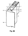
- FIG. 4 shows by way of example for the profile connector 10, the connection of a first profile 40 by means of the profile connector 10 with a second profile 50 in an upper region of a frame, for example, a glass door leaf.
- the profile connector 10 is inserted in a first step on the front side in the first profile 40.
- the profile connector 10 is already braced to a predetermined extent with the first profile 40, so that in a subsequent step, the second profile 50 with a receiving portion 52 at an angle of preferably 90 ° to the first profile 40 are pushed onto the base 11 of the profile connector 10 can, without the risk that the profile connector 10 could solve the first profile 40.
- FIG. 4A Screw 1 shown in the center is screwed through the passage opening 13a into the projection 13, whereupon the projection 13 spreads apart and securely clamps the profile connector 10 in the first profile 40. Then, the second profile 50 is placed or pushed at an angle of 90 ° to the first profile 40 on the base 11 with its receiving portion 52.
- the placement of the second profile 50 takes place in such a way that passage openings 53 are aligned with corresponding passage openings 11a, 11a of the base 11 of the profile connector 10.
- a clamping spring 70 which will be discussed later, be inserted into an attachment portion 51 of the second profile 50 such that through holes 71 a, 71 a of a fixing portion 71 of the clamping spring 70 are aligned with corresponding through holes 53 of the second profile 50.
- a side sealing profile 60 by means of a fixing member 61 can be inserted into the second profile 50 in the end sections of wall sections 51 a, 51 a of the second profile 50 frontally.
- the fixing member 61 has attachment portions 61 a, 61 a in the form of projections which are formed so as to engage in grooves of the end portions of the wall portions 51 a, 51 a of an attachment portion 51 of the profile connector 50.
- FIG. 4B shows the parts of FIG. 4A in the assembled state.
- the profiles 40, 50 act in the assembled state for a viewer from the outside rectangular.
- FIGS 5A and 5B shown variant are for the purpose side walls 41 b, 42 and 51 a, 52 a of two profiles 40, 50 to be joined together beveled with respect to their respective longitudinal extent.
- the side walls 41 b, 42 protrude above the end face of the first profile 40, whereas the side walls 51 a, 52 a of the second profile 50 with respect to the previous embodiment have triangular cutouts.
- the profiles 40, 50 continue to assemble as described by means of profile connectors 10, 20, 30.
- the optical effect is analogous to the effect realized by means of the beveled end surfaces described above.
- the clamping spring 70 has instead of circular slot-shaped through holes 71 a, 71 a, which allows an arrangement of the clamping spring 70 in different positions with respect to the second profile 50.
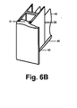
- FIG. 6 shows by way of example for the profile connector 10 connecting the first profile 40 by means of the profile connector 10 with a second profile 50 now in a lower region of the aforementioned frame.
- the first profile 40 and the profile connector 10 are in contrast to FIG. 4 arranged rotated by 180 ° about the x-coordinate axis.
- FIG. 4A If no clamping spring 70 is attached here. However, it is possible without problems, such a clamping spring 70 analogous to FIG. 4A to attach to the second profile 50.
- a cover profile 80 with guide sections 81, 81 is inserted into end sections 41c, 41c of the first profile 40. Thereafter, the assembly of the second profile 50 and the side seal profile 60 is substantially analogous to the description FIG. 4A ,
- the passage opening 13 a of the profile connector 10 has, in the example shown, a diameter which essentially corresponds to a diameter of the passage openings 11 a of the profile connector 10.
- the first fixing screw 1 is not according to FIG. 4A directly after the insertion of the profile connector 10 is screwed into the first profile 40 but only after the second profile 50 is positioned accordingly, then additionally through a corresponding, additional passage opening 53 in the second profile 50 through the passage opening 13a in the projection 13 into it.
- FIG. 6A shows the arrangement of all parts in exploded view
- FIG. 6B the arrangement in the assembled state shows.
- the assembly of the second profile 50 on the first profile 40 can be subsequently clipped from below into the first profile 40, provided that the sections 81, 81 permit this.
- This can be done, for example, by the guide sections 81, 81 not having a rectangular cross-section but a cross-section in the form of a FIG. 5A upright triangle have.
- profile connectors 10, 20, 30 are simple in construction and allow easy attachment to a first profile 40 and further easy mounting of a respective second profile 50.
Landscapes
- Engineering & Computer Science (AREA)
- General Engineering & Computer Science (AREA)
- Mechanical Engineering (AREA)
- Civil Engineering (AREA)
- Structural Engineering (AREA)
- Connection Of Plates (AREA)
- Helmets And Other Head Coverings (AREA)
Applications Claiming Priority (1)
| Application Number | Priority Date | Filing Date | Title |
|---|---|---|---|
| DE200810008695 DE102008008695A1 (de) | 2008-02-11 | 2008-02-11 | Profilverbinder |
Publications (3)
| Publication Number | Publication Date |
|---|---|
| EP2088335A2 true EP2088335A2 (fr) | 2009-08-12 |
| EP2088335A3 EP2088335A3 (fr) | 2013-05-01 |
| EP2088335B1 EP2088335B1 (fr) | 2015-04-15 |
Family
ID=40671391
Family Applications (1)
| Application Number | Title | Priority Date | Filing Date |
|---|---|---|---|
| EP20090001590 Active EP2088335B1 (fr) | 2008-02-11 | 2009-02-05 | Connecteur de profilés |
Country Status (3)
| Country | Link |
|---|---|
| EP (1) | EP2088335B1 (fr) |
| DE (1) | DE102008008695A1 (fr) |
| ES (1) | ES2541461T3 (fr) |
Cited By (2)
| Publication number | Priority date | Publication date | Assignee | Title |
|---|---|---|---|---|
| EP3081733A1 (fr) * | 2015-04-14 | 2016-10-19 | Deceuninck nv | Élément de paroi ou élément de porte |
| DE102019101451A1 (de) | 2019-01-21 | 2020-07-23 | Dormakaba Deutschland Gmbh | Profilanordnung |
Citations (1)
| Publication number | Priority date | Publication date | Assignee | Title |
|---|---|---|---|---|
| DE202007008969U1 (de) | 2007-06-12 | 2007-08-30 | Holscher, Winfried K.W. | Profilverbinder sowie Profilverbund |
Family Cites Families (3)
| Publication number | Priority date | Publication date | Assignee | Title |
|---|---|---|---|---|
| DE9406655U1 (de) * | 1994-04-21 | 1994-06-30 | MFT GmbH - Moderne Fenster Technik -, 26871 Papenburg | Verbindungsstück für winklig aneinanderstoßende Hohlprofilstäbe |
| GB9912337D0 (en) * | 1999-05-26 | 1999-07-28 | Deceuninck Plastics Ind Nv | Mechanical joint |
| DE202006013250U1 (de) * | 2006-08-29 | 2006-11-09 | Hecht International Gmbh | Eckverbinder zum Verbinden von mindestens zwei Profilleisten |
-
2008
- 2008-02-11 DE DE200810008695 patent/DE102008008695A1/de not_active Withdrawn
-
2009
- 2009-02-05 EP EP20090001590 patent/EP2088335B1/fr active Active
- 2009-02-05 ES ES09001590.0T patent/ES2541461T3/es active Active
Patent Citations (1)
| Publication number | Priority date | Publication date | Assignee | Title |
|---|---|---|---|---|
| DE202007008969U1 (de) | 2007-06-12 | 2007-08-30 | Holscher, Winfried K.W. | Profilverbinder sowie Profilverbund |
Cited By (7)
| Publication number | Priority date | Publication date | Assignee | Title |
|---|---|---|---|---|
| EP3081733A1 (fr) * | 2015-04-14 | 2016-10-19 | Deceuninck nv | Élément de paroi ou élément de porte |
| WO2016166244A1 (fr) * | 2015-04-14 | 2016-10-20 | Deceuninck Nv | Élément de porte ou élément mural |
| RU2689034C2 (ru) * | 2015-04-14 | 2019-05-23 | Десеюнинк Нв | Элемент двери или элемент стены |
| DE102019101451A1 (de) | 2019-01-21 | 2020-07-23 | Dormakaba Deutschland Gmbh | Profilanordnung |
| WO2020152180A1 (fr) | 2019-01-21 | 2020-07-30 | Dormakaba Deutschland Gmbh | Agencement de profilés |
| US20220098924A1 (en) * | 2019-01-21 | 2022-03-31 | Dormakaba Deutschland Gmbh | Profile system |
| US11840878B2 (en) * | 2019-01-21 | 2023-12-12 | Dormakaba Deutschland Gmbh | Profile system |
Also Published As
| Publication number | Publication date |
|---|---|
| EP2088335B1 (fr) | 2015-04-15 |
| DE102008008695A1 (de) | 2009-08-13 |
| ES2541461T3 (es) | 2015-07-20 |
| EP2088335A3 (fr) | 2013-05-01 |
Similar Documents
| Publication | Publication Date | Title |
|---|---|---|
| EP3381323B1 (fr) | Insert de panneau arrière | |
| EP1343974B2 (fr) | Systeme de connexion pour profiles | |
| EP4230881B1 (fr) | Elément de liaison | |
| EP4357627A2 (fr) | Dispositif de compensation de tolérance | |
| WO2000036311A1 (fr) | Dispositif d'assemblage permettant de reunir une premiere piece a une seconde | |
| EP1382784B1 (fr) | Elément de ferrure pour un volet de fenêtre en aluminium | |
| DE3838957A1 (de) | Isolierende verbindungsvorrichtung fuer bauplatten | |
| EP1234985B1 (fr) | Système de liaison par serrage | |
| EP2088337A2 (fr) | Profilé et système de profilés | |
| DE3038341A1 (de) | In eine wandoeffnung eines ersten bauteils einsetzbares und ueber eine rastnut mit diesem verrastbares aufnahmeteil | |
| EP2088335B1 (fr) | Connecteur de profilés | |
| DE102019204525A1 (de) | Befestigungsklemme | |
| EP1898041B1 (fr) | Procedé et dispositif de montage d'accessoires sur cadres de bâtiments | |
| AT7578U1 (de) | Verbindung von zwei profilstäben und absperrungskonstruktion mit derartigen verbindungen | |
| DE10357589B3 (de) | Befestigungselement für Führungsschienen von Sonnenschutzanlagen | |
| AT403500B (de) | Beschlagteileverbindung | |
| EP1503029B1 (fr) | Système de jalousies | |
| DE19752619A1 (de) | Verbindungsbauteil für eine Fassadenkonstruktion und Fassadenkonstruktion | |
| AT524670B1 (de) | Dübel zum Verbinden von zwei Bauteilen | |
| EP1186723A2 (fr) | Dispositif de fixation pour une façade avec montants et traverses | |
| EP2385200A2 (fr) | Elément de ferrure pour la fixation dans une rainure de ferrure en forme de C | |
| DE102005044127B4 (de) | Trägerteil für einen Sammelschienenträger sowie Sammelschienenträger | |
| EP4151865B1 (fr) | Système de connecteur | |
| EP4686840A1 (fr) | Connecteur, ensemble et procédé | |
| EP3153891B1 (fr) | Porte comprenant un écarteur réglable en longueur et son procédé de montage |
Legal Events
| Date | Code | Title | Description |
|---|---|---|---|
| PUAI | Public reference made under article 153(3) epc to a published international application that has entered the european phase |
Free format text: ORIGINAL CODE: 0009012 |
|
| AK | Designated contracting states |
Kind code of ref document: A2 Designated state(s): AT BE BG CH CY CZ DE DK EE ES FI FR GB GR HR HU IE IS IT LI LT LU LV MC MK MT NL NO PL PT RO SE SI SK TR |
|
| AX | Request for extension of the european patent |
Extension state: AL BA RS |
|
| RAP1 | Party data changed (applicant data changed or rights of an application transferred) |
Owner name: DORMA GMBH + CO. KG |
|
| PUAL | Search report despatched |
Free format text: ORIGINAL CODE: 0009013 |
|
| AK | Designated contracting states |
Kind code of ref document: A3 Designated state(s): AT BE BG CH CY CZ DE DK EE ES FI FR GB GR HR HU IE IS IT LI LT LU LV MC MK MT NL NO PL PT RO SE SI SK TR |
|
| AX | Request for extension of the european patent |
Extension state: AL BA RS |
|
| RIC1 | Information provided on ipc code assigned before grant |
Ipc: F16B 7/00 20060101AFI20130328BHEP Ipc: E06B 3/964 20060101ALI20130328BHEP Ipc: F16B 7/18 20060101ALI20130328BHEP |
|
| 17P | Request for examination filed |
Effective date: 20131104 |
|
| RBV | Designated contracting states (corrected) |
Designated state(s): AT BE BG CH CY CZ DE DK EE ES FI FR GB GR HR HU IE IS IT LI LT LU LV MC MK MT NL NO PL PT RO SE SI SK TR |
|
| AKX | Designation fees paid |
Designated state(s): AT BE BG CH CY CZ DE DK EE ES FI FR GB GR HR HU IE IS IT LI LT LU LV MC MK MT NL NO PL PT RO SE SI SK TR |
|
| 17Q | First examination report despatched |
Effective date: 20140107 |
|
| GRAP | Despatch of communication of intention to grant a patent |
Free format text: ORIGINAL CODE: EPIDOSNIGR1 |
|
| INTG | Intention to grant announced |
Effective date: 20141104 |
|
| GRAS | Grant fee paid |
Free format text: ORIGINAL CODE: EPIDOSNIGR3 |
|
| GRAA | (expected) grant |
Free format text: ORIGINAL CODE: 0009210 |
|
| RAP1 | Party data changed (applicant data changed or rights of an application transferred) |
Owner name: DORMA DEUTSCHLAND GMBH |
|
| AK | Designated contracting states |
Kind code of ref document: B1 Designated state(s): AT BE BG CH CY CZ DE DK EE ES FI FR GB GR HR HU IE IS IT LI LT LU LV MC MK MT NL NO PL PT RO SE SI SK TR |
|
| REG | Reference to a national code |
Ref country code: GB Ref legal event code: FG4D Free format text: NOT ENGLISH Ref country code: CH Ref legal event code: EP |
|
| REG | Reference to a national code |
Ref country code: IE Ref legal event code: FG4D Free format text: LANGUAGE OF EP DOCUMENT: GERMAN |
|
| REG | Reference to a national code |
Ref country code: AT Ref legal event code: REF Ref document number: 722167 Country of ref document: AT Kind code of ref document: T Effective date: 20150515 |
|
| REG | Reference to a national code |
Ref country code: DE Ref legal event code: R096 Ref document number: 502009010904 Country of ref document: DE Effective date: 20150528 |
|
| REG | Reference to a national code |
Ref country code: ES Ref legal event code: FG2A Ref document number: 2541461 Country of ref document: ES Kind code of ref document: T3 Effective date: 20150720 |
|
| REG | Reference to a national code |
Ref country code: NL Ref legal event code: VDEP Effective date: 20150415 |
|
| REG | Reference to a national code |
Ref country code: LT Ref legal event code: MG4D |
|
| PG25 | Lapsed in a contracting state [announced via postgrant information from national office to epo] |
Ref country code: NL Free format text: LAPSE BECAUSE OF FAILURE TO SUBMIT A TRANSLATION OF THE DESCRIPTION OR TO PAY THE FEE WITHIN THE PRESCRIBED TIME-LIMIT Effective date: 20150415 |
|
| REG | Reference to a national code |
Ref country code: GB Ref legal event code: S117 Free format text: REQUEST FILED; REQUEST FOR CORRECTION UNDER SECTION 117 FILED ON 14 SEPTEMBER 2015 |
|
| PG25 | Lapsed in a contracting state [announced via postgrant information from national office to epo] |
Ref country code: LT Free format text: LAPSE BECAUSE OF FAILURE TO SUBMIT A TRANSLATION OF THE DESCRIPTION OR TO PAY THE FEE WITHIN THE PRESCRIBED TIME-LIMIT Effective date: 20150415 Ref country code: PT Free format text: LAPSE BECAUSE OF FAILURE TO SUBMIT A TRANSLATION OF THE DESCRIPTION OR TO PAY THE FEE WITHIN THE PRESCRIBED TIME-LIMIT Effective date: 20150817 Ref country code: FI Free format text: LAPSE BECAUSE OF FAILURE TO SUBMIT A TRANSLATION OF THE DESCRIPTION OR TO PAY THE FEE WITHIN THE PRESCRIBED TIME-LIMIT Effective date: 20150415 Ref country code: NO Free format text: LAPSE BECAUSE OF FAILURE TO SUBMIT A TRANSLATION OF THE DESCRIPTION OR TO PAY THE FEE WITHIN THE PRESCRIBED TIME-LIMIT Effective date: 20150715 Ref country code: HR Free format text: LAPSE BECAUSE OF FAILURE TO SUBMIT A TRANSLATION OF THE DESCRIPTION OR TO PAY THE FEE WITHIN THE PRESCRIBED TIME-LIMIT Effective date: 20150415 |
|
| REG | Reference to a national code |
Ref country code: GB Ref legal event code: S117 Free format text: CORRECTIONS ALLOWED; REQUEST FOR CORRECTION UNDER SECTION 117 FILED ON 14 SEPTEMBER 2015, ALLOWED ON 08 OCTOBER 2015 |
|
| PG25 | Lapsed in a contracting state [announced via postgrant information from national office to epo] |
Ref country code: IS Free format text: LAPSE BECAUSE OF FAILURE TO SUBMIT A TRANSLATION OF THE DESCRIPTION OR TO PAY THE FEE WITHIN THE PRESCRIBED TIME-LIMIT Effective date: 20150815 Ref country code: LV Free format text: LAPSE BECAUSE OF FAILURE TO SUBMIT A TRANSLATION OF THE DESCRIPTION OR TO PAY THE FEE WITHIN THE PRESCRIBED TIME-LIMIT Effective date: 20150415 Ref country code: GR Free format text: LAPSE BECAUSE OF FAILURE TO SUBMIT A TRANSLATION OF THE DESCRIPTION OR TO PAY THE FEE WITHIN THE PRESCRIBED TIME-LIMIT Effective date: 20150716 |
|
| REG | Reference to a national code |
Ref country code: DE Ref legal event code: R097 Ref document number: 502009010904 Country of ref document: DE |
|
| PG25 | Lapsed in a contracting state [announced via postgrant information from national office to epo] |
Ref country code: DK Free format text: LAPSE BECAUSE OF FAILURE TO SUBMIT A TRANSLATION OF THE DESCRIPTION OR TO PAY THE FEE WITHIN THE PRESCRIBED TIME-LIMIT Effective date: 20150415 Ref country code: EE Free format text: LAPSE BECAUSE OF FAILURE TO SUBMIT A TRANSLATION OF THE DESCRIPTION OR TO PAY THE FEE WITHIN THE PRESCRIBED TIME-LIMIT Effective date: 20150415 |
|
| REG | Reference to a national code |
Ref country code: FR Ref legal event code: PLFP Year of fee payment: 8 |
|
| PLBE | No opposition filed within time limit |
Free format text: ORIGINAL CODE: 0009261 |
|
| STAA | Information on the status of an ep patent application or granted ep patent |
Free format text: STATUS: NO OPPOSITION FILED WITHIN TIME LIMIT |
|
| PG25 | Lapsed in a contracting state [announced via postgrant information from national office to epo] |
Ref country code: PL Free format text: LAPSE BECAUSE OF FAILURE TO SUBMIT A TRANSLATION OF THE DESCRIPTION OR TO PAY THE FEE WITHIN THE PRESCRIBED TIME-LIMIT Effective date: 20150415 Ref country code: RO Free format text: LAPSE BECAUSE OF NON-PAYMENT OF DUE FEES Effective date: 20150415 Ref country code: SK Free format text: LAPSE BECAUSE OF FAILURE TO SUBMIT A TRANSLATION OF THE DESCRIPTION OR TO PAY THE FEE WITHIN THE PRESCRIBED TIME-LIMIT Effective date: 20150415 Ref country code: CZ Free format text: LAPSE BECAUSE OF FAILURE TO SUBMIT A TRANSLATION OF THE DESCRIPTION OR TO PAY THE FEE WITHIN THE PRESCRIBED TIME-LIMIT Effective date: 20150415 |
|
| 26N | No opposition filed |
Effective date: 20160118 |
|
| PG25 | Lapsed in a contracting state [announced via postgrant information from national office to epo] |
Ref country code: BE Free format text: LAPSE BECAUSE OF NON-PAYMENT OF DUE FEES Effective date: 20160229 Ref country code: SI Free format text: LAPSE BECAUSE OF FAILURE TO SUBMIT A TRANSLATION OF THE DESCRIPTION OR TO PAY THE FEE WITHIN THE PRESCRIBED TIME-LIMIT Effective date: 20150415 |
|
| PG25 | Lapsed in a contracting state [announced via postgrant information from national office to epo] |
Ref country code: MC Free format text: LAPSE BECAUSE OF FAILURE TO SUBMIT A TRANSLATION OF THE DESCRIPTION OR TO PAY THE FEE WITHIN THE PRESCRIBED TIME-LIMIT Effective date: 20150415 Ref country code: LU Free format text: LAPSE BECAUSE OF FAILURE TO SUBMIT A TRANSLATION OF THE DESCRIPTION OR TO PAY THE FEE WITHIN THE PRESCRIBED TIME-LIMIT Effective date: 20160205 |
|
| REG | Reference to a national code |
Ref country code: CH Ref legal event code: PL |
|
| PG25 | Lapsed in a contracting state [announced via postgrant information from national office to epo] |
Ref country code: CH Free format text: LAPSE BECAUSE OF NON-PAYMENT OF DUE FEES Effective date: 20160229 Ref country code: LI Free format text: LAPSE BECAUSE OF NON-PAYMENT OF DUE FEES Effective date: 20160229 |
|
| REG | Reference to a national code |
Ref country code: IE Ref legal event code: MM4A |
|
| PG25 | Lapsed in a contracting state [announced via postgrant information from national office to epo] |
Ref country code: IE Free format text: LAPSE BECAUSE OF NON-PAYMENT OF DUE FEES Effective date: 20160205 |
|
| REG | Reference to a national code |
Ref country code: FR Ref legal event code: PLFP Year of fee payment: 9 |
|
| REG | Reference to a national code |
Ref country code: AT Ref legal event code: MM01 Ref document number: 722167 Country of ref document: AT Kind code of ref document: T Effective date: 20160205 |
|
| REG | Reference to a national code |
Ref country code: DE Ref legal event code: R082 Ref document number: 502009010904 Country of ref document: DE Representative=s name: BALDER IP LAW, S.L., ES Ref country code: DE Ref legal event code: R081 Ref document number: 502009010904 Country of ref document: DE Owner name: DORMAKABA DEUTSCHLAND GMBH, DE Free format text: FORMER OWNER: DORMA DEUTSCHLAND GMBH, 58256 ENNEPETAL, DE |
|
| PG25 | Lapsed in a contracting state [announced via postgrant information from national office to epo] |
Ref country code: AT Free format text: LAPSE BECAUSE OF NON-PAYMENT OF DUE FEES Effective date: 20160205 |
|
| PG25 | Lapsed in a contracting state [announced via postgrant information from national office to epo] |
Ref country code: SE Free format text: LAPSE BECAUSE OF FAILURE TO SUBMIT A TRANSLATION OF THE DESCRIPTION OR TO PAY THE FEE WITHIN THE PRESCRIBED TIME-LIMIT Effective date: 20150415 |
|
| PG25 | Lapsed in a contracting state [announced via postgrant information from national office to epo] |
Ref country code: MT Free format text: LAPSE BECAUSE OF FAILURE TO SUBMIT A TRANSLATION OF THE DESCRIPTION OR TO PAY THE FEE WITHIN THE PRESCRIBED TIME-LIMIT Effective date: 20150415 |
|
| REG | Reference to a national code |
Ref country code: ES Ref legal event code: PC2A Owner name: DORMAKABA DEUTSCHLAND GMBH Effective date: 20171004 |
|
| REG | Reference to a national code |
Ref country code: FR Ref legal event code: CD Owner name: DORMA DEUTSCHLAND GMBH, DE Effective date: 20171003 |
|
| REG | Reference to a national code |
Ref country code: FR Ref legal event code: PLFP Year of fee payment: 10 |
|
| PG25 | Lapsed in a contracting state [announced via postgrant information from national office to epo] |
Ref country code: CY Free format text: LAPSE BECAUSE OF FAILURE TO SUBMIT A TRANSLATION OF THE DESCRIPTION OR TO PAY THE FEE WITHIN THE PRESCRIBED TIME-LIMIT Effective date: 20150415 Ref country code: HU Free format text: LAPSE BECAUSE OF FAILURE TO SUBMIT A TRANSLATION OF THE DESCRIPTION OR TO PAY THE FEE WITHIN THE PRESCRIBED TIME-LIMIT; INVALID AB INITIO Effective date: 20090205 |
|
| PG25 | Lapsed in a contracting state [announced via postgrant information from national office to epo] |
Ref country code: TR Free format text: LAPSE BECAUSE OF FAILURE TO SUBMIT A TRANSLATION OF THE DESCRIPTION OR TO PAY THE FEE WITHIN THE PRESCRIBED TIME-LIMIT Effective date: 20150415 Ref country code: MK Free format text: LAPSE BECAUSE OF FAILURE TO SUBMIT A TRANSLATION OF THE DESCRIPTION OR TO PAY THE FEE WITHIN THE PRESCRIBED TIME-LIMIT Effective date: 20150415 |
|
| PG25 | Lapsed in a contracting state [announced via postgrant information from national office to epo] |
Ref country code: BG Free format text: LAPSE BECAUSE OF FAILURE TO SUBMIT A TRANSLATION OF THE DESCRIPTION OR TO PAY THE FEE WITHIN THE PRESCRIBED TIME-LIMIT Effective date: 20150415 |
|
| PGFP | Annual fee paid to national office [announced via postgrant information from national office to epo] |
Ref country code: ES Payment date: 20250328 Year of fee payment: 17 |
|
| PGFP | Annual fee paid to national office [announced via postgrant information from national office to epo] |
Ref country code: GB Payment date: 20260219 Year of fee payment: 18 |
|
| PGFP | Annual fee paid to national office [announced via postgrant information from national office to epo] |
Ref country code: DE Payment date: 20260218 Year of fee payment: 18 |
|
| PGFP | Annual fee paid to national office [announced via postgrant information from national office to epo] |
Ref country code: IT Payment date: 20260224 Year of fee payment: 18 |
|
| PGFP | Annual fee paid to national office [announced via postgrant information from national office to epo] |
Ref country code: FR Payment date: 20260218 Year of fee payment: 18 |