EP2088367A1 - Eclairage - Google Patents
Eclairage Download PDFInfo
- Publication number
- EP2088367A1 EP2088367A1 EP08002456A EP08002456A EP2088367A1 EP 2088367 A1 EP2088367 A1 EP 2088367A1 EP 08002456 A EP08002456 A EP 08002456A EP 08002456 A EP08002456 A EP 08002456A EP 2088367 A1 EP2088367 A1 EP 2088367A1
- Authority
- EP
- European Patent Office
- Prior art keywords
- frame
- housing
- luminaire according
- link
- flat
- Prior art date
- Legal status (The legal status is an assumption and is not a legal conclusion. Google has not performed a legal analysis and makes no representation as to the accuracy of the status listed.)
- Granted
Links
- 238000010168 coupling process Methods 0.000 claims description 12
- 230000008878 coupling Effects 0.000 claims description 11
- 238000005859 coupling reaction Methods 0.000 claims description 11
- 238000000149 argon plasma sintering Methods 0.000 claims description 3
- 230000000903 blocking effect Effects 0.000 claims 2
- 238000012423 maintenance Methods 0.000 description 9
- 241000238631 Hexapoda Species 0.000 description 5
- 238000010276 construction Methods 0.000 description 2
- 239000005336 safety glass Substances 0.000 description 2
- 238000007789 sealing Methods 0.000 description 2
- 238000004140 cleaning Methods 0.000 description 1
- 230000000694 effects Effects 0.000 description 1
- 239000011521 glass Substances 0.000 description 1
- 238000009434 installation Methods 0.000 description 1
- 230000003993 interaction Effects 0.000 description 1
- 239000010410 layer Substances 0.000 description 1
- 239000002356 single layer Substances 0.000 description 1
- 238000011144 upstream manufacturing Methods 0.000 description 1
Images

Classifications
-
- F—MECHANICAL ENGINEERING; LIGHTING; HEATING; WEAPONS; BLASTING
- F21—LIGHTING
- F21V—FUNCTIONAL FEATURES OR DETAILS OF LIGHTING DEVICES OR SYSTEMS THEREOF; STRUCTURAL COMBINATIONS OF LIGHTING DEVICES WITH OTHER ARTICLES, NOT OTHERWISE PROVIDED FOR
- F21V17/00—Fastening of component parts of lighting devices, e.g. shades, globes, refractors, reflectors, filters, screens, grids or protective cages
- F21V17/10—Fastening of component parts of lighting devices, e.g. shades, globes, refractors, reflectors, filters, screens, grids or protective cages characterised by specific fastening means or way of fastening
- F21V17/107—Fastening of component parts of lighting devices, e.g. shades, globes, refractors, reflectors, filters, screens, grids or protective cages characterised by specific fastening means or way of fastening using hinge joints
-
- F—MECHANICAL ENGINEERING; LIGHTING; HEATING; WEAPONS; BLASTING
- F21—LIGHTING
- F21S—NON-PORTABLE LIGHTING DEVICES; SYSTEMS THEREOF; VEHICLE LIGHTING DEVICES SPECIALLY ADAPTED FOR VEHICLE EXTERIORS
- F21S8/00—Lighting devices intended for fixed installation
- F21S8/02—Lighting devices intended for fixed installation of recess-mounted type, e.g. downlighters
Definitions
- the present invention relates to a luminaire, in particular spotlight, surface light and the like, with a housing accommodating the luminous means and the associated electrical components and a frame associated with the housing for holding a disc-shaped, in particular light-scattering, light-emitting surface.
- the frame carrying the light exit surface is releasably connected to the housing to ensure the required accessibility to the light sources.
- the frame with the housings are screwed executed in the known lights or there are provided between the frame and housing by exerting pressure or train releasable detent connections, which are still attached safety reasons between the housing and frame still safety ropes.
- the object of the invention is to provide a luminaire of the type described with little design effort so that given simple basic assembly of the lamp problem-free and convenient accessibility of the housing interior for maintenance purposes, lamp replacement and radiator settings and always an absolutely reliable and secure connection between the housing and Frame is guaranteed.
- the frame is each frontally connected via a pair of flat link with the housing, that the pair of flat links hinged on the one hand on the inner wall of the housing and on the other hand on the outside of the end wall of the frame and in the gap region between the housing and Frame is located, and that the frame on the flat link pairs between a free accessibility to the light-ensuring opening position and a preferably flush with the opening plane of the housing closed position is pivotable.
- each pair of flat link consists of a support arm and a control link, which are connected relative to each other so offset articulation points on the housing and the frame that a located in the rear area of the lamp virtual pivot axis is formed and affect the handlebars, the free accessibility of the housing interior in any way ,
- stops which are realized by means of support and control links, that is, these links are designed so that they come into contact with each other in the open position and in the closed position of the frame and thus in the respective End positions have stop function.
- At least one retaining spring is preferably effective, wherein this retaining spring is preferably one in each case Federstabbügel fixed to the housing, which engages by means of a curved latching portion in a trained in the frame retaining notch.
- the desired holding function can also be achieved in other ways, in particular via push-push closures or magnetic holders.
- An embodiment of the invention which is characterized by increasing the variability and also by improving the maintenance options, is that the frame-side ends of support and control links are hinged to a coupling rail, the force and positively inserted into a guide groove in the frame end wall - and can be locked.
- This standardized connection possibility of a frame to the housing creates the possibility to combine the housing with different equipped frame in a simple way, for example, to use frames that have differently designed light exit surfaces or are equipped with partial reflectors, because these differently shaped frame can each be connected and locked by a simple coupling process with the housing-fixed coupling rail.
- the flat link pairs and also in the pivoted position of the frame spring locking can be arranged in a narrow gap between the housing and frame, locally before a dustproof according to IP44 and also light-tight, from further inside labyrinth sections of the housing and the frame formed labyrinth gap seal. In this way, it is ensured that no light originating from the light sources can penetrate into the housing gap receiving the flat-link pairs. This is of particular importance because it eliminates the effect of attracting insects and there is no danger of insects getting into the gap.
- the invention thus provides an optimally prefabricatable, easy-to-install luminaire, which enables a trouble-free, feasible by a person maintenance, the forced operation between the housing and frame always consistent appearance in the closed state with a defined, dust-tight and light-free gap between the housing and frame guaranteed.
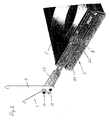
- Fig. 1 shows an embodied as recessed light embodiment of a lamp according to the invention with a box-shaped housing 1, in which arranged in a row a plurality of bulbs 2 are added.
- a frame 3 which surrounds a preferably light-scattering light exit surface 4 in the form of a single-layer or multi-layer glass or plastic disk and carries it.
- a plurality of the respective lamps 2 associated partial reflectors 5 are mounted on the light exit surface 3.
- the frame 3 is connected to the housing 1 via pairs of supporting links 6 and control links 7, which are arranged in the gap between the housing 1 and the frame 3 in the end face areas. All the handlebars 6, 7 are designed as a flat bar and require little space, that is they can be accommodated problem-free in a shell gap between the housing 1 and frame 3, since they are located in a plane.
- the support arm 6 is hinged at one end to a Stirnwandeck Scheme 10 of the frame and at its other end to an approximately overlying area of the housing 1 at a pivot point 13, while the longer compared to the support arm 6 control arm 7 with one end adjacent the support arm. 6 but offset outwardly and forwardly articulated at a pivot point 17 on the frame 3.
- the pivot point 14 of the control arm 7 on the housing is located closer to the pivot point 13 of the support arm on the opening plane of the housing 1.
- the control link 7 has in the vicinity of its frame-side pivot point 12 has a recess 16 in which engages the frame-side end of the support arm 6 with the frame open and in the fully open position for Plant comes, so that between the support arm 6 and the control link 7, an opening position defining stop is formed.
- the permanently hinged to the housing 1 support and control links 6, 7 are according to the illustrated embodiment, not directly on the frame 3, but rather hinged to a coupling rail 20, as shown particularly clearly in Fig. 2 you can see.
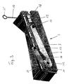
- Fig. 2 shows the frame 3 after Fig. 1 separated from him with the connecting housing 1 in the coupling rail 20.
- the coupling rail 20 of the support arm 6 and the control link 7 are articulated to each other offset, via the articulation points 11 and 12.
- the coupling rail 20 is non-positively and positively in a guide groove 21 in the frame end wall 9 can be inserted and locked in its end position via a snap-locking connection 22 or fixable.
- the frame 3 can be easily separated from the housing 1, and it can be seen that in this way with the housing 1 also differently configured or populated frame can be coupled, which not only increases the variability of the overall light, but especially contributes to the ease of installation.
- Fig. 3 shows the frame 3 regardless of the housing 1, but the support arm 6 and the control link 7 are shown in the position they occupy when the frame 3 is pivoted into the housing and has reached its end position in the housing.
- This end position is in turn defined by a resulting stop 24 between the support arm 6 and the control link 7.
- the frame is held by a retaining spring 17, which engages with a latching portion 18 in a retaining notch 19 of the frame 3.
- the retaining spring 17 is connected via a ring eyelet 25 - as in Fig. 1 can be seen - attached to this housing 1 and guided laterally.
- at least one flat link pair 6, 7 can still be associated with a tension spring acting in the closing direction.
- a defined circumferential gap between the housing 1 and the frame 3 in the closed position of the lamp can be ensured by the positive guidance provided between the housing 1 and the frame 3 according to the invention.
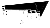
- the support and control links and the spring detent 17 are arranged in front of a deeper gap formed in the labyrinth gap seal 23, as in the partial representation after Fig. 4 you can see.
- the labyrinth seal 23 is realized by wall sections of the housing 1 and frame 3. This labyrinth seal ensures that from the interior of the housing 1 no light in the Handlebar 6, 7 receiving gap can pass, that is, there is a light-free and thus no insect attraction gap.
- the embodiment described above relates to a recessed luminaire, but the advantages of the inventive design of the lamp are particularly suitable for wearing in suspended lights, in which the housing occupies a defined position during maintenance, but may be more or less vibrated in the work to be performed.
Landscapes
- Engineering & Computer Science (AREA)
- General Engineering & Computer Science (AREA)
- Securing Globes, Refractors, Reflectors Or The Like (AREA)
- Arrangement Of Elements, Cooling, Sealing, Or The Like Of Lighting Devices (AREA)
- Illuminated Signs And Luminous Advertising (AREA)
- Vessels And Coating Films For Discharge Lamps (AREA)
Priority Applications (4)
| Application Number | Priority Date | Filing Date | Title |
|---|---|---|---|
| DE502008001074T DE502008001074D1 (de) | 2008-02-11 | 2008-02-11 | Leuchte |
| EP08002456A EP2088367B1 (fr) | 2008-02-11 | 2008-02-11 | Eclairage |
| AT08002456T ATE476627T1 (de) | 2008-02-11 | 2008-02-11 | Leuchte |
| CN200910006285.9A CN101526195B (zh) | 2008-02-11 | 2009-02-11 | 照明装置 |
Applications Claiming Priority (1)
| Application Number | Priority Date | Filing Date | Title |
|---|---|---|---|
| EP08002456A EP2088367B1 (fr) | 2008-02-11 | 2008-02-11 | Eclairage |
Publications (2)
| Publication Number | Publication Date |
|---|---|
| EP2088367A1 true EP2088367A1 (fr) | 2009-08-12 |
| EP2088367B1 EP2088367B1 (fr) | 2010-08-04 |
Family
ID=39481230
Family Applications (1)
| Application Number | Title | Priority Date | Filing Date |
|---|---|---|---|
| EP08002456A Not-in-force EP2088367B1 (fr) | 2008-02-11 | 2008-02-11 | Eclairage |
Country Status (4)
| Country | Link |
|---|---|
| EP (1) | EP2088367B1 (fr) |
| CN (1) | CN101526195B (fr) |
| AT (1) | ATE476627T1 (fr) |
| DE (1) | DE502008001074D1 (fr) |
Families Citing this family (2)
| Publication number | Priority date | Publication date | Assignee | Title |
|---|---|---|---|---|
| DE102011052582A1 (de) * | 2011-08-11 | 2013-02-14 | Hella Kgaa Hueck & Co. | Außenleuchte |
| DE102023132212B3 (de) | 2023-11-20 | 2025-01-16 | Rzb Rudolf Zimmermann, Bamberg Gmbh | Mehrteiliger Gehäusekörper |
Citations (3)
| Publication number | Priority date | Publication date | Assignee | Title |
|---|---|---|---|---|
| EP0485811A2 (fr) | 1990-11-14 | 1992-05-20 | Ansorg Gesellschaft mit beschränkter Haftung | Dispositif d'eclairage |
| US5682131A (en) | 1996-04-04 | 1997-10-28 | Gow; Thomas W. | Retractable tamper resistant annunciator |
| US6517216B1 (en) * | 1999-09-17 | 2003-02-11 | Brightline, L.P. | Adjustable fluorescent lighting fixtures |
Family Cites Families (1)
| Publication number | Priority date | Publication date | Assignee | Title |
|---|---|---|---|---|
| CN2319684Y (zh) * | 1997-06-17 | 1999-05-19 | 柳州铁路局科学技术研究所 | 隧道照明灯具防尘装置 |
-
2008
- 2008-02-11 EP EP08002456A patent/EP2088367B1/fr not_active Not-in-force
- 2008-02-11 AT AT08002456T patent/ATE476627T1/de active
- 2008-02-11 DE DE502008001074T patent/DE502008001074D1/de active Active
-
2009
- 2009-02-11 CN CN200910006285.9A patent/CN101526195B/zh not_active Expired - Fee Related
Patent Citations (3)
| Publication number | Priority date | Publication date | Assignee | Title |
|---|---|---|---|---|
| EP0485811A2 (fr) | 1990-11-14 | 1992-05-20 | Ansorg Gesellschaft mit beschränkter Haftung | Dispositif d'eclairage |
| US5682131A (en) | 1996-04-04 | 1997-10-28 | Gow; Thomas W. | Retractable tamper resistant annunciator |
| US6517216B1 (en) * | 1999-09-17 | 2003-02-11 | Brightline, L.P. | Adjustable fluorescent lighting fixtures |
Also Published As
| Publication number | Publication date |
|---|---|
| EP2088367B1 (fr) | 2010-08-04 |
| CN101526195B (zh) | 2013-09-25 |
| CN101526195A (zh) | 2009-09-09 |
| DE502008001074D1 (de) | 2010-09-16 |
| ATE476627T1 (de) | 2010-08-15 |
Similar Documents
| Publication | Publication Date | Title |
|---|---|---|
| EP2373923B1 (fr) | Lumiere avec une chassis interieur fixe au moins partiellment d'une manière amovible | |
| EP3114400B1 (fr) | Luminaire ou ensemble lumineux comprenant un élément support allongé et un module lumineux fixé de manière libérable | |
| DE102004048484A1 (de) | Verschlussmechanismus für Leuchten | |
| EP2796780B1 (fr) | Luminaire doté d'une caractéristique de rayonnement lumineux réglable | |
| EP2088367B1 (fr) | Eclairage | |
| EP4354017A1 (fr) | Système de fixation pour une lampe, élément de fixation et lampe | |
| CH712491A2 (de) | Leuchte zur Deckenmontage mit Scharnier. | |
| DE102012209347B4 (de) | Leuchte, insbesondere für ein Lichtband | |
| DE19808912C2 (de) | Innenraumleuchte mit einer Einrichtung zum vereinfachten Lampenwechsel | |
| DE10022338B4 (de) | Rohrschelle zum Befestigen von Hängescheinwerfern | |
| DE10009567A1 (de) | Leuchte in Rohrform | |
| EP2711622B1 (fr) | Lampe dotée d'une protection contre le contact | |
| EP3171073B1 (fr) | Éclairage encastré | |
| DE10234459B4 (de) | Verbindungselement zum Befestigen eines optischen Leuchtenbauteils an einer Leuchte und Leuchte | |
| DE4411890A1 (de) | Leuchte | |
| DE202013103419U1 (de) | Leuchte mit Trägerelement und auswechselbarem Leuchtmittel-Modul | |
| EP2672171B1 (fr) | Lampe, notamment pour une bande lumineuse | |
| EP3217079B1 (fr) | Dispositif d'éclairage | |
| DE202015101294U1 (de) | Zusammengesetzte Wagenlampe | |
| DE102008059178B4 (de) | Leuchtenanordnung mit einer Versorgungsschiene | |
| EP2107298A1 (fr) | Lampe suspendue allongée | |
| DE202010016151U1 (de) | Beleuchtungseinrichtung mit platzsparend zu bedienenden Mitteln zur Lampenbefestigung | |
| DE922424C (de) | Decken- und Wandleuchte | |
| DE20113476U1 (de) | Längliches Leuchtmittel | |
| DE1838026U (de) | Leuchte, insbesondere wand- und deckenleuchte. |
Legal Events
| Date | Code | Title | Description |
|---|---|---|---|
| PUAI | Public reference made under article 153(3) epc to a published international application that has entered the european phase |
Free format text: ORIGINAL CODE: 0009012 |
|
| 17P | Request for examination filed |
Effective date: 20080722 |
|
| AK | Designated contracting states |
Kind code of ref document: A1 Designated state(s): AT BE BG CH CY CZ DE DK EE ES FI FR GB GR HR HU IE IS IT LI LT LU LV MC MT NL NO PL PT RO SE SI SK TR |
|
| AX | Request for extension of the european patent |
Extension state: AL BA MK RS |
|
| GRAP | Despatch of communication of intention to grant a patent |
Free format text: ORIGINAL CODE: EPIDOSNIGR1 |
|
| GRAS | Grant fee paid |
Free format text: ORIGINAL CODE: EPIDOSNIGR3 |
|
| AKX | Designation fees paid |
Designated state(s): AT CH DE GB LI |
|
| GRAA | (expected) grant |
Free format text: ORIGINAL CODE: 0009210 |
|
| AK | Designated contracting states |
Kind code of ref document: B1 Designated state(s): AT CH DE GB LI |
|
| REG | Reference to a national code |
Ref country code: GB Ref legal event code: FG4D Free format text: NOT ENGLISH |
|
| REG | Reference to a national code |
Ref country code: CH Ref legal event code: EP |
|
| REF | Corresponds to: |
Ref document number: 502008001074 Country of ref document: DE Date of ref document: 20100916 Kind code of ref document: P |
|
| REG | Reference to a national code |
Ref country code: CH Ref legal event code: NV Representative=s name: DR. GRAF & PARTNER AG INTELLECTUAL PROPERTY |
|
| PLBE | No opposition filed within time limit |
Free format text: ORIGINAL CODE: 0009261 |
|
| STAA | Information on the status of an ep patent application or granted ep patent |
Free format text: STATUS: NO OPPOSITION FILED WITHIN TIME LIMIT |
|
| 26N | No opposition filed |
Effective date: 20110506 |
|
| REG | Reference to a national code |
Ref country code: DE Ref legal event code: R097 Ref document number: 502008001074 Country of ref document: DE Effective date: 20110506 |
|
| PGFP | Annual fee paid to national office [announced via postgrant information from national office to epo] |
Ref country code: CH Payment date: 20170217 Year of fee payment: 10 Ref country code: DE Payment date: 20170217 Year of fee payment: 10 |
|
| PGFP | Annual fee paid to national office [announced via postgrant information from national office to epo] |
Ref country code: GB Payment date: 20170216 Year of fee payment: 10 Ref country code: AT Payment date: 20170217 Year of fee payment: 10 |
|
| REG | Reference to a national code |
Ref country code: DE Ref legal event code: R119 Ref document number: 502008001074 Country of ref document: DE |
|
| REG | Reference to a national code |
Ref country code: CH Ref legal event code: PL |
|
| REG | Reference to a national code |
Ref country code: AT Ref legal event code: MM01 Ref document number: 476627 Country of ref document: AT Kind code of ref document: T Effective date: 20180211 |
|
| GBPC | Gb: european patent ceased through non-payment of renewal fee |
Effective date: 20180211 |
|
| PG25 | Lapsed in a contracting state [announced via postgrant information from national office to epo] |
Ref country code: LI Free format text: LAPSE BECAUSE OF NON-PAYMENT OF DUE FEES Effective date: 20180228 Ref country code: CH Free format text: LAPSE BECAUSE OF NON-PAYMENT OF DUE FEES Effective date: 20180228 Ref country code: AT Free format text: LAPSE BECAUSE OF NON-PAYMENT OF DUE FEES Effective date: 20180211 |
|
| PG25 | Lapsed in a contracting state [announced via postgrant information from national office to epo] |
Ref country code: DE Free format text: LAPSE BECAUSE OF NON-PAYMENT OF DUE FEES Effective date: 20180901 |
|
| PG25 | Lapsed in a contracting state [announced via postgrant information from national office to epo] |
Ref country code: GB Free format text: LAPSE BECAUSE OF NON-PAYMENT OF DUE FEES Effective date: 20180211 |