EP2088474A2 - Procédé et appareil de formation d'images - Google Patents
Procédé et appareil de formation d'images Download PDFInfo
- Publication number
- EP2088474A2 EP2088474A2 EP09151328A EP09151328A EP2088474A2 EP 2088474 A2 EP2088474 A2 EP 2088474A2 EP 09151328 A EP09151328 A EP 09151328A EP 09151328 A EP09151328 A EP 09151328A EP 2088474 A2 EP2088474 A2 EP 2088474A2
- Authority
- EP
- European Patent Office
- Prior art keywords
- toner
- image
- image bearing
- bearing members
- forming apparatus
- Prior art date
- Legal status (The legal status is an assumption and is not a legal conclusion. Google has not performed a legal analysis and makes no representation as to the accuracy of the status listed.)
- Withdrawn
Links
- 238000000034 method Methods 0.000 title claims description 93
- 238000012546 transfer Methods 0.000 claims abstract description 391
- 239000000654 additive Substances 0.000 claims abstract description 87
- 238000003825 pressing Methods 0.000 claims abstract description 43
- 239000011159 matrix material Substances 0.000 claims abstract description 21
- 229920005989 resin Polymers 0.000 claims description 59
- 239000011347 resin Substances 0.000 claims description 59
- 239000003086 colorant Substances 0.000 claims description 35
- 239000011230 binding agent Substances 0.000 claims description 21
- 239000004645 polyester resin Substances 0.000 claims description 21
- 229920001225 polyester resin Polymers 0.000 claims description 21
- 239000002245 particle Substances 0.000 description 81
- 230000008569 process Effects 0.000 description 50
- 230000032258 transport Effects 0.000 description 48
- 238000011161 development Methods 0.000 description 44
- 238000004140 cleaning Methods 0.000 description 30
- 229920000728 polyester Polymers 0.000 description 30
- 239000000047 product Substances 0.000 description 28
- 230000000052 comparative effect Effects 0.000 description 26
- 238000007639 printing Methods 0.000 description 22
- 239000011800 void material Substances 0.000 description 20
- 239000000243 solution Substances 0.000 description 17
- 239000003960 organic solvent Substances 0.000 description 16
- 239000006185 dispersion Substances 0.000 description 15
- 239000010410 layer Substances 0.000 description 15
- 230000002441 reversible effect Effects 0.000 description 15
- 229910052799 carbon Inorganic materials 0.000 description 14
- 239000003125 aqueous solvent Substances 0.000 description 13
- 230000000694 effects Effects 0.000 description 13
- XLYOFNOQVPJJNP-UHFFFAOYSA-N water Substances O XLYOFNOQVPJJNP-UHFFFAOYSA-N 0.000 description 13
- XEKOWRVHYACXOJ-UHFFFAOYSA-N Ethyl acetate Chemical compound CCOC(C)=O XEKOWRVHYACXOJ-UHFFFAOYSA-N 0.000 description 12
- 239000003795 chemical substances by application Substances 0.000 description 12
- 239000007788 liquid Substances 0.000 description 12
- 239000000126 substance Substances 0.000 description 12
- 239000011521 glass Substances 0.000 description 11
- -1 ployazo red Chemical compound 0.000 description 11
- 238000000926 separation method Methods 0.000 description 11
- 239000000725 suspension Substances 0.000 description 11
- VYPSYNLAJGMNEJ-UHFFFAOYSA-N Silicium dioxide Chemical compound O=[Si]=O VYPSYNLAJGMNEJ-UHFFFAOYSA-N 0.000 description 10
- PPBRXRYQALVLMV-UHFFFAOYSA-N Styrene Chemical compound C=CC1=CC=CC=C1 PPBRXRYQALVLMV-UHFFFAOYSA-N 0.000 description 10
- 238000002474 experimental method Methods 0.000 description 10
- 239000000463 material Substances 0.000 description 10
- 229920001577 copolymer Polymers 0.000 description 9
- 239000010419 fine particle Substances 0.000 description 9
- 229920001721 polyimide Polymers 0.000 description 9
- 239000009719 polyimide resin Substances 0.000 description 9
- 239000005056 polyisocyanate Substances 0.000 description 9
- 229920001228 polyisocyanate Polymers 0.000 description 9
- 230000002829 reductive effect Effects 0.000 description 9
- 238000001514 detection method Methods 0.000 description 8
- 239000000203 mixture Substances 0.000 description 8
- 239000002253 acid Substances 0.000 description 7
- 230000007423 decrease Effects 0.000 description 7
- 229910052751 metal Inorganic materials 0.000 description 7
- 239000002184 metal Substances 0.000 description 7
- 229920005862 polyol Polymers 0.000 description 7
- 150000003077 polyols Chemical class 0.000 description 7
- 239000000843 powder Substances 0.000 description 7
- ZWEHNKRNPOVVGH-UHFFFAOYSA-N 2-Butanone Chemical compound CCC(C)=O ZWEHNKRNPOVVGH-UHFFFAOYSA-N 0.000 description 6
- 239000006229 carbon black Substances 0.000 description 6
- 238000006243 chemical reaction Methods 0.000 description 6
- 238000009826 distribution Methods 0.000 description 6
- 235000019439 ethyl acetate Nutrition 0.000 description 6
- IQPQWNKOIGAROB-UHFFFAOYSA-N isocyanate group Chemical group [N-]=C=O IQPQWNKOIGAROB-UHFFFAOYSA-N 0.000 description 6
- 230000003287 optical effect Effects 0.000 description 6
- 229920000642 polymer Polymers 0.000 description 6
- 239000004094 surface-active agent Substances 0.000 description 6
- 239000004594 Masterbatch (MB) Substances 0.000 description 5
- 150000001875 compounds Chemical class 0.000 description 5
- 239000011162 core material Substances 0.000 description 5
- 230000003247 decreasing effect Effects 0.000 description 5
- 150000002148 esters Chemical class 0.000 description 5
- 238000011156 evaluation Methods 0.000 description 5
- 230000009477 glass transition Effects 0.000 description 5
- 230000001788 irregular Effects 0.000 description 5
- 125000000391 vinyl group Chemical group [H]C([*])=C([H])[H] 0.000 description 5
- 229920002554 vinyl polymer Polymers 0.000 description 5
- 239000001993 wax Substances 0.000 description 5
- UFHFLCQGNIYNRP-UHFFFAOYSA-N Hydrogen Chemical compound [H][H] UFHFLCQGNIYNRP-UHFFFAOYSA-N 0.000 description 4
- FAPWRFPIFSIZLT-UHFFFAOYSA-M Sodium chloride Chemical compound [Na+].[Cl-] FAPWRFPIFSIZLT-UHFFFAOYSA-M 0.000 description 4
- MCMNRKCIXSYSNV-UHFFFAOYSA-N Zirconium dioxide Chemical compound O=[Zr]=O MCMNRKCIXSYSNV-UHFFFAOYSA-N 0.000 description 4
- 238000013019 agitation Methods 0.000 description 4
- 239000011324 bead Substances 0.000 description 4
- 239000011248 coating agent Substances 0.000 description 4
- 238000000576 coating method Methods 0.000 description 4
- 239000003822 epoxy resin Substances 0.000 description 4
- 239000001257 hydrogen Substances 0.000 description 4
- 229910052739 hydrogen Inorganic materials 0.000 description 4
- 238000005259 measurement Methods 0.000 description 4
- 239000003921 oil Substances 0.000 description 4
- 230000035699 permeability Effects 0.000 description 4
- 229920000647 polyepoxide Polymers 0.000 description 4
- 238000006116 polymerization reaction Methods 0.000 description 4
- 239000011164 primary particle Substances 0.000 description 4
- 239000000523 sample Substances 0.000 description 4
- 239000000377 silicon dioxide Substances 0.000 description 4
- 239000007787 solid Substances 0.000 description 4
- 238000011144 upstream manufacturing Methods 0.000 description 4
- UBOXGVDOUJQMTN-UHFFFAOYSA-N 1,1,2-trichloroethane Chemical compound ClCC(Cl)Cl UBOXGVDOUJQMTN-UHFFFAOYSA-N 0.000 description 3
- UHOVQNZJYSORNB-UHFFFAOYSA-N Benzene Chemical compound C1=CC=CC=C1 UHOVQNZJYSORNB-UHFFFAOYSA-N 0.000 description 3
- YMWUJEATGCHHMB-UHFFFAOYSA-N Dichloromethane Chemical compound ClCCl YMWUJEATGCHHMB-UHFFFAOYSA-N 0.000 description 3
- YXFVVABEGXRONW-UHFFFAOYSA-N Toluene Chemical compound CC1=CC=CC=C1 YXFVVABEGXRONW-UHFFFAOYSA-N 0.000 description 3
- 150000001412 amines Chemical class 0.000 description 3
- 125000003277 amino group Chemical group 0.000 description 3
- 230000015572 biosynthetic process Effects 0.000 description 3
- 210000000078 claw Anatomy 0.000 description 3
- 230000002596 correlated effect Effects 0.000 description 3
- 230000002950 deficient Effects 0.000 description 3
- 239000002270 dispersing agent Substances 0.000 description 3
- 230000006870 function Effects 0.000 description 3
- 238000004519 manufacturing process Methods 0.000 description 3
- 239000000049 pigment Substances 0.000 description 3
- 238000006068 polycondensation reaction Methods 0.000 description 3
- 239000011342 resin composition Substances 0.000 description 3
- 239000002904 solvent Substances 0.000 description 3
- ZSDSQXJSNMTJDA-UHFFFAOYSA-N trifluralin Chemical compound CCCN(CCC)C1=C([N+]([O-])=O)C=C(C(F)(F)F)C=C1[N+]([O-])=O ZSDSQXJSNMTJDA-UHFFFAOYSA-N 0.000 description 3
- 229910000859 α-Fe Inorganic materials 0.000 description 3
- HZAXFHJVJLSVMW-UHFFFAOYSA-N 2-Aminoethan-1-ol Chemical compound NCCO HZAXFHJVJLSVMW-UHFFFAOYSA-N 0.000 description 2
- RNLHGQLZWXBQNY-UHFFFAOYSA-N 3-(aminomethyl)-3,5,5-trimethylcyclohexan-1-amine Chemical compound CC1(C)CC(N)CC(C)(CN)C1 RNLHGQLZWXBQNY-UHFFFAOYSA-N 0.000 description 2
- 239000004925 Acrylic resin Substances 0.000 description 2
- 229920000178 Acrylic resin Polymers 0.000 description 2
- PAYRUJLWNCNPSJ-UHFFFAOYSA-N Aniline Chemical compound NC1=CC=CC=C1 PAYRUJLWNCNPSJ-UHFFFAOYSA-N 0.000 description 2
- VTYYLEPIZMXCLO-UHFFFAOYSA-L Calcium carbonate Chemical compound [Ca+2].[O-]C([O-])=O VTYYLEPIZMXCLO-UHFFFAOYSA-L 0.000 description 2
- OKTJSMMVPCPJKN-UHFFFAOYSA-N Carbon Chemical compound [C] OKTJSMMVPCPJKN-UHFFFAOYSA-N 0.000 description 2
- HEDRZPFGACZZDS-UHFFFAOYSA-N Chloroform Chemical compound ClC(Cl)Cl HEDRZPFGACZZDS-UHFFFAOYSA-N 0.000 description 2
- VZCYOOQTPOCHFL-OWOJBTEDSA-N Fumaric acid Chemical compound OC(=O)\C=C\C(O)=O VZCYOOQTPOCHFL-OWOJBTEDSA-N 0.000 description 2
- OFOBLEOULBTSOW-UHFFFAOYSA-N Malonic acid Chemical compound OC(=O)CC(O)=O OFOBLEOULBTSOW-UHFFFAOYSA-N 0.000 description 2
- CERQOIWHTDAKMF-UHFFFAOYSA-N Methacrylic acid Chemical compound CC(=C)C(O)=O CERQOIWHTDAKMF-UHFFFAOYSA-N 0.000 description 2
- 229920000459 Nitrile rubber Polymers 0.000 description 2
- 239000004698 Polyethylene Substances 0.000 description 2
- 102100040160 Rabankyrin-5 Human genes 0.000 description 2
- 101710086049 Rabankyrin-5 Proteins 0.000 description 2
- KKEYFWRCBNTPAC-UHFFFAOYSA-N Terephthalic acid Chemical compound OC(=O)C1=CC=C(C(O)=O)C=C1 KKEYFWRCBNTPAC-UHFFFAOYSA-N 0.000 description 2
- GWEVSGVZZGPLCZ-UHFFFAOYSA-N Titan oxide Chemical compound O=[Ti]=O GWEVSGVZZGPLCZ-UHFFFAOYSA-N 0.000 description 2
- XLOMVQKBTHCTTD-UHFFFAOYSA-N Zinc monoxide Chemical compound [Zn]=O XLOMVQKBTHCTTD-UHFFFAOYSA-N 0.000 description 2
- WNLRTRBMVRJNCN-UHFFFAOYSA-N adipic acid Chemical compound OC(=O)CCCCC(O)=O WNLRTRBMVRJNCN-UHFFFAOYSA-N 0.000 description 2
- ADCOVFLJGNWWNZ-UHFFFAOYSA-N antimony trioxide Chemical compound O=[Sb]O[Sb]=O ADCOVFLJGNWWNZ-UHFFFAOYSA-N 0.000 description 2
- TZCXTZWJZNENPQ-UHFFFAOYSA-L barium sulfate Chemical compound [Ba+2].[O-]S([O-])(=O)=O TZCXTZWJZNENPQ-UHFFFAOYSA-L 0.000 description 2
- IISBACLAFKSPIT-UHFFFAOYSA-N bisphenol A Chemical compound C=1C=C(O)C=CC=1C(C)(C)C1=CC=C(O)C=C1 IISBACLAFKSPIT-UHFFFAOYSA-N 0.000 description 2
- 230000000903 blocking effect Effects 0.000 description 2
- 239000004203 carnauba wax Substances 0.000 description 2
- 235000013869 carnauba wax Nutrition 0.000 description 2
- 230000005494 condensation Effects 0.000 description 2
- 238000011109 contamination Methods 0.000 description 2
- 238000004132 cross linking Methods 0.000 description 2
- 229920001971 elastomer Polymers 0.000 description 2
- 239000003792 electrolyte Substances 0.000 description 2
- 238000004945 emulsification Methods 0.000 description 2
- 238000010556 emulsion polymerization method Methods 0.000 description 2
- JBKVHLHDHHXQEQ-UHFFFAOYSA-N epsilon-caprolactam Chemical compound O=C1CCCCCN1 JBKVHLHDHHXQEQ-UHFFFAOYSA-N 0.000 description 2
- 230000002349 favourable effect Effects 0.000 description 2
- NAQMVNRVTILPCV-UHFFFAOYSA-N hexane-1,6-diamine Chemical compound NCCCCCCN NAQMVNRVTILPCV-UHFFFAOYSA-N 0.000 description 2
- 125000004435 hydrogen atom Chemical group [H]* 0.000 description 2
- 238000003384 imaging method Methods 0.000 description 2
- 239000004615 ingredient Substances 0.000 description 2
- 238000005342 ion exchange Methods 0.000 description 2
- ZXEKIIBDNHEJCQ-UHFFFAOYSA-N isobutanol Chemical compound CC(C)CO ZXEKIIBDNHEJCQ-UHFFFAOYSA-N 0.000 description 2
- 150000002576 ketones Chemical class 0.000 description 2
- 238000011068 loading method Methods 0.000 description 2
- NUKZAGXMHTUAFE-UHFFFAOYSA-N methyl hexanoate Chemical compound CCCCCC(=O)OC NUKZAGXMHTUAFE-UHFFFAOYSA-N 0.000 description 2
- 238000002156 mixing Methods 0.000 description 2
- 230000002093 peripheral effect Effects 0.000 description 2
- XNGIFLGASWRNHJ-UHFFFAOYSA-N phthalic acid Chemical compound OC(=O)C1=CC=CC=C1C(O)=O XNGIFLGASWRNHJ-UHFFFAOYSA-N 0.000 description 2
- 229920003023 plastic Polymers 0.000 description 2
- 239000004033 plastic Substances 0.000 description 2
- 238000012643 polycondensation polymerization Methods 0.000 description 2
- 229920000573 polyethylene Polymers 0.000 description 2
- 229920005749 polyurethane resin Polymers 0.000 description 2
- 238000010298 pulverizing process Methods 0.000 description 2
- CYIDZMCFTVVTJO-UHFFFAOYSA-N pyromellitic acid Chemical compound OC(=O)C1=CC(C(O)=O)=C(C(O)=O)C=C1C(O)=O CYIDZMCFTVVTJO-UHFFFAOYSA-N 0.000 description 2
- 150000003242 quaternary ammonium salts Chemical class 0.000 description 2
- 239000005060 rubber Substances 0.000 description 2
- YGSDEFSMJLZEOE-UHFFFAOYSA-N salicylic acid Chemical class OC(=O)C1=CC=CC=C1O YGSDEFSMJLZEOE-UHFFFAOYSA-N 0.000 description 2
- 150000003839 salts Chemical class 0.000 description 2
- 229920002050 silicone resin Polymers 0.000 description 2
- 238000005549 size reduction Methods 0.000 description 2
- 239000011780 sodium chloride Substances 0.000 description 2
- 229920005792 styrene-acrylic resin Polymers 0.000 description 2
- 238000010558 suspension polymerization method Methods 0.000 description 2
- OGIDPMRJRNCKJF-UHFFFAOYSA-N titanium oxide Inorganic materials [Ti]=O OGIDPMRJRNCKJF-UHFFFAOYSA-N 0.000 description 2
- VZCYOOQTPOCHFL-UHFFFAOYSA-N trans-butenedioic acid Natural products OC(=O)C=CC(O)=O VZCYOOQTPOCHFL-UHFFFAOYSA-N 0.000 description 2
- ARCGXLSVLAOJQL-UHFFFAOYSA-N trimellitic acid Chemical compound OC(=O)C1=CC=C(C(O)=O)C(C(O)=O)=C1 ARCGXLSVLAOJQL-UHFFFAOYSA-N 0.000 description 2
- WSLDOOZREJYCGB-UHFFFAOYSA-N 1,2-Dichloroethane Chemical compound ClCCCl WSLDOOZREJYCGB-UHFFFAOYSA-N 0.000 description 1
- OVBFMUAFNIIQAL-UHFFFAOYSA-N 1,4-diisocyanatobutane Chemical compound O=C=NCCCCN=C=O OVBFMUAFNIIQAL-UHFFFAOYSA-N 0.000 description 1
- FFRBMBIXVSCUFS-UHFFFAOYSA-N 2,4-dinitro-1-naphthol Chemical compound C1=CC=C2C(O)=C([N+]([O-])=O)C=C([N+]([O-])=O)C2=C1 FFRBMBIXVSCUFS-UHFFFAOYSA-N 0.000 description 1
- MFYSUUPKMDJYPF-UHFFFAOYSA-N 2-[(4-methyl-2-nitrophenyl)diazenyl]-3-oxo-n-phenylbutanamide Chemical compound C=1C=CC=CC=1NC(=O)C(C(=O)C)N=NC1=CC=C(C)C=C1[N+]([O-])=O MFYSUUPKMDJYPF-UHFFFAOYSA-N 0.000 description 1
- TZUBWGMDFVLGGT-UHFFFAOYSA-N 3,3-dichloroprop-1-enyl acetate Chemical compound CC(=O)OC=CC(Cl)Cl TZUBWGMDFVLGGT-UHFFFAOYSA-N 0.000 description 1
- PYSRRFNXTXNWCD-UHFFFAOYSA-N 3-(2-phenylethenyl)furan-2,5-dione Chemical compound O=C1OC(=O)C(C=CC=2C=CC=CC=2)=C1 PYSRRFNXTXNWCD-UHFFFAOYSA-N 0.000 description 1
- CKRJGDYKYQUNIM-UHFFFAOYSA-N 3-fluoro-2,2-dimethylpropanoic acid Chemical compound FCC(C)(C)C(O)=O CKRJGDYKYQUNIM-UHFFFAOYSA-N 0.000 description 1
- UPMLOUAZCHDJJD-UHFFFAOYSA-N 4,4'-Diphenylmethane Diisocyanate Chemical compound C1=CC(N=C=O)=CC=C1CC1=CC=C(N=C=O)C=C1 UPMLOUAZCHDJJD-UHFFFAOYSA-N 0.000 description 1
- YBRVSVVVWCFQMG-UHFFFAOYSA-N 4,4'-diaminodiphenylmethane Chemical compound C1=CC(N)=CC=C1CC1=CC=C(N)C=C1 YBRVSVVVWCFQMG-UHFFFAOYSA-N 0.000 description 1
- NLHHRLWOUZZQLW-UHFFFAOYSA-N Acrylonitrile Chemical compound C=CC#N NLHHRLWOUZZQLW-UHFFFAOYSA-N 0.000 description 1
- IJGRMHOSHXDMSA-UHFFFAOYSA-N Atomic nitrogen Chemical compound N#N IJGRMHOSHXDMSA-UHFFFAOYSA-N 0.000 description 1
- 239000004215 Carbon black (E152) Substances 0.000 description 1
- 229920002134 Carboxymethyl cellulose Polymers 0.000 description 1
- VYZAMTAEIAYCRO-UHFFFAOYSA-N Chromium Chemical compound [Cr] VYZAMTAEIAYCRO-UHFFFAOYSA-N 0.000 description 1
- YCKRFDGAMUMZLT-UHFFFAOYSA-N Fluorine atom Chemical compound [F] YCKRFDGAMUMZLT-UHFFFAOYSA-N 0.000 description 1
- 241000206672 Gelidium Species 0.000 description 1
- 239000005057 Hexamethylene diisocyanate Substances 0.000 description 1
- XEEYBQQBJWHFJM-UHFFFAOYSA-N Iron Chemical group [Fe] XEEYBQQBJWHFJM-UHFFFAOYSA-N 0.000 description 1
- 239000005058 Isophorone diisocyanate Substances 0.000 description 1
- FYYHWMGAXLPEAU-UHFFFAOYSA-N Magnesium Chemical compound [Mg] FYYHWMGAXLPEAU-UHFFFAOYSA-N 0.000 description 1
- 239000004640 Melamine resin Substances 0.000 description 1
- 229920000877 Melamine resin Polymers 0.000 description 1
- NTIZESTWPVYFNL-UHFFFAOYSA-N Methyl isobutyl ketone Chemical compound CC(C)CC(C)=O NTIZESTWPVYFNL-UHFFFAOYSA-N 0.000 description 1
- UIHCLUNTQKBZGK-UHFFFAOYSA-N Methyl isobutyl ketone Natural products CCC(C)C(C)=O UIHCLUNTQKBZGK-UHFFFAOYSA-N 0.000 description 1
- CTQNGGLPUBDAKN-UHFFFAOYSA-N O-Xylene Chemical compound CC1=CC=CC=C1C CTQNGGLPUBDAKN-UHFFFAOYSA-N 0.000 description 1
- 239000004743 Polypropylene Substances 0.000 description 1
- NRCMAYZCPIVABH-UHFFFAOYSA-N Quinacridone Chemical compound N1C2=CC=CC=C2C(=O)C2=C1C=C1C(=O)C3=CC=CC=C3NC1=C2 NRCMAYZCPIVABH-UHFFFAOYSA-N 0.000 description 1
- 229910052581 Si3N4 Inorganic materials 0.000 description 1
- 229920000147 Styrene maleic anhydride Polymers 0.000 description 1
- KDYFGRWQOYBRFD-UHFFFAOYSA-N Succinic acid Natural products OC(=O)CCC(O)=O KDYFGRWQOYBRFD-UHFFFAOYSA-N 0.000 description 1
- RTAQQCXQSZGOHL-UHFFFAOYSA-N Titanium Chemical compound [Ti] RTAQQCXQSZGOHL-UHFFFAOYSA-N 0.000 description 1
- XSTXAVWGXDQKEL-UHFFFAOYSA-N Trichloroethylene Chemical group ClC=C(Cl)Cl XSTXAVWGXDQKEL-UHFFFAOYSA-N 0.000 description 1
- 229920001807 Urea-formaldehyde Polymers 0.000 description 1
- HJPOKQICBCJGHE-UHFFFAOYSA-J [C+4].[Cl-].[Cl-].[Cl-].[Cl-] Chemical compound [C+4].[Cl-].[Cl-].[Cl-].[Cl-] HJPOKQICBCJGHE-UHFFFAOYSA-J 0.000 description 1
- 230000002159 abnormal effect Effects 0.000 description 1
- 238000010521 absorption reaction Methods 0.000 description 1
- ATMLPEJAVWINOF-UHFFFAOYSA-N acrylic acid acrylic acid Chemical compound OC(=O)C=C.OC(=O)C=C ATMLPEJAVWINOF-UHFFFAOYSA-N 0.000 description 1
- 239000001361 adipic acid Substances 0.000 description 1
- 235000011037 adipic acid Nutrition 0.000 description 1
- 125000002723 alicyclic group Chemical group 0.000 description 1
- 125000001931 aliphatic group Chemical group 0.000 description 1
- 150000004996 alkyl benzenes Chemical class 0.000 description 1
- PNEYBMLMFCGWSK-UHFFFAOYSA-N aluminium oxide Inorganic materials [O-2].[O-2].[O-2].[Al+3].[Al+3] PNEYBMLMFCGWSK-UHFFFAOYSA-N 0.000 description 1
- 150000001413 amino acids Chemical class 0.000 description 1
- 150000001414 amino alcohols Chemical class 0.000 description 1
- 239000007864 aqueous solution Substances 0.000 description 1
- QFFVPLLCYGOFPU-UHFFFAOYSA-N barium chromate Chemical compound [Ba+2].[O-][Cr]([O-])(=O)=O QFFVPLLCYGOFPU-UHFFFAOYSA-N 0.000 description 1
- JRPBQTZRNDNNOP-UHFFFAOYSA-N barium titanate Chemical compound [Ba+2].[Ba+2].[O-][Ti]([O-])([O-])[O-] JRPBQTZRNDNNOP-UHFFFAOYSA-N 0.000 description 1
- 229910002113 barium titanate Inorganic materials 0.000 description 1
- AYJRCSIUFZENHW-DEQYMQKBSA-L barium(2+);oxomethanediolate Chemical compound [Ba+2].[O-][14C]([O-])=O AYJRCSIUFZENHW-DEQYMQKBSA-L 0.000 description 1
- 229940077388 benzenesulfonate Drugs 0.000 description 1
- UCMIRNVEIXFBKS-UHFFFAOYSA-N beta-alanine Chemical compound NCCC(O)=O UCMIRNVEIXFBKS-UHFFFAOYSA-N 0.000 description 1
- 229940106691 bisphenol a Drugs 0.000 description 1
- 238000009835 boiling Methods 0.000 description 1
- MTAZNLWOLGHBHU-UHFFFAOYSA-N butadiene-styrene rubber Chemical compound C=CC=C.C=CC1=CC=CC=C1 MTAZNLWOLGHBHU-UHFFFAOYSA-N 0.000 description 1
- KDYFGRWQOYBRFD-NUQCWPJISA-N butanedioic acid Chemical compound O[14C](=O)CC[14C](O)=O KDYFGRWQOYBRFD-NUQCWPJISA-N 0.000 description 1
- IDVFKHFBDNEFQQ-UHFFFAOYSA-N butyl prop-2-enoate 2-methylidene-5-phenylpent-4-enoic acid 2-methylprop-2-enoic acid oxirane Chemical compound C1CO1.C(C(=C)C)(=O)O.C(C=C)(=O)OCCCC.C(=CC1=CC=CC=C1)CC(C(=O)O)=C IDVFKHFBDNEFQQ-UHFFFAOYSA-N 0.000 description 1
- 229910000019 calcium carbonate Inorganic materials 0.000 description 1
- AOWKSNWVBZGMTJ-UHFFFAOYSA-N calcium titanate Chemical compound [Ca+2].[O-][Ti]([O-])=O AOWKSNWVBZGMTJ-UHFFFAOYSA-N 0.000 description 1
- 239000001768 carboxy methyl cellulose Substances 0.000 description 1
- 235000010948 carboxy methyl cellulose Nutrition 0.000 description 1
- 239000008112 carboxymethyl-cellulose Substances 0.000 description 1
- 235000012730 carminic acid Nutrition 0.000 description 1
- 229910000420 cerium oxide Inorganic materials 0.000 description 1
- 230000008859 change Effects 0.000 description 1
- 239000013522 chelant Substances 0.000 description 1
- MVPPADPHJFYWMZ-UHFFFAOYSA-N chlorobenzene Chemical compound ClC1=CC=CC=C1 MVPPADPHJFYWMZ-UHFFFAOYSA-N 0.000 description 1
- 229910052804 chromium Inorganic materials 0.000 description 1
- 239000011651 chromium Substances 0.000 description 1
- 239000004927 clay Substances 0.000 description 1
- 239000000084 colloidal system Substances 0.000 description 1
- 238000001816 cooling Methods 0.000 description 1
- XCJYREBRNVKWGJ-UHFFFAOYSA-N copper(II) phthalocyanine Chemical compound [Cu+2].C12=CC=CC=C2C(N=C2[N-]C(C3=CC=CC=C32)=N2)=NC1=NC([C]1C=CC=CC1=1)=NC=1N=C1[C]3C=CC=CC3=C2[N-]1 XCJYREBRNVKWGJ-UHFFFAOYSA-N 0.000 description 1
- 230000000875 corresponding effect Effects 0.000 description 1
- UFULAYFCSOUIOV-UHFFFAOYSA-N cysteamine Chemical compound NCCS UFULAYFCSOUIOV-UHFFFAOYSA-N 0.000 description 1
- 238000010586 diagram Methods 0.000 description 1
- 150000004985 diamines Chemical class 0.000 description 1
- QDOXWKRWXJOMAK-UHFFFAOYSA-N dichromium trioxide Chemical compound O=[Cr]O[Cr]=O QDOXWKRWXJOMAK-UHFFFAOYSA-N 0.000 description 1
- GKGXKPRVOZNVPQ-UHFFFAOYSA-N diisocyanatomethylcyclohexane Chemical compound O=C=NC(N=C=O)C1CCCCC1 GKGXKPRVOZNVPQ-UHFFFAOYSA-N 0.000 description 1
- 229910001873 dinitrogen Inorganic materials 0.000 description 1
- FBNCDTLHQPLASV-UHFFFAOYSA-L disodium;5-methyl-2-[[5-(4-methyl-2-sulfonatoanilino)-9,10-dioxoanthracen-1-yl]amino]benzenesulfonate Chemical compound [Na+].[Na+].[O-]S(=O)(=O)C1=CC(C)=CC=C1NC1=CC=CC2=C1C(=O)C1=CC=CC(NC=3C(=CC(C)=CC=3)S([O-])(=O)=O)=C1C2=O FBNCDTLHQPLASV-UHFFFAOYSA-L 0.000 description 1
- PLYDMIIYRWUYBP-UHFFFAOYSA-N ethyl 4-[[2-chloro-4-[3-chloro-4-[(3-ethoxycarbonyl-5-oxo-1-phenyl-4h-pyrazol-4-yl)diazenyl]phenyl]phenyl]diazenyl]-5-oxo-1-phenyl-4h-pyrazole-3-carboxylate Chemical compound CCOC(=O)C1=NN(C=2C=CC=CC=2)C(=O)C1N=NC(C(=C1)Cl)=CC=C1C(C=C1Cl)=CC=C1N=NC(C(=N1)C(=O)OCC)C(=O)N1C1=CC=CC=C1 PLYDMIIYRWUYBP-UHFFFAOYSA-N 0.000 description 1
- 238000001914 filtration Methods 0.000 description 1
- 239000011737 fluorine Substances 0.000 description 1
- 229910052731 fluorine Inorganic materials 0.000 description 1
- 239000001530 fumaric acid Substances 0.000 description 1
- 125000000524 functional group Chemical group 0.000 description 1
- 239000007789 gas Substances 0.000 description 1
- 238000010438 heat treatment Methods 0.000 description 1
- RRAMGCGOFNQTLD-UHFFFAOYSA-N hexamethylene diisocyanate Chemical compound O=C=NCCCCCCN=C=O RRAMGCGOFNQTLD-UHFFFAOYSA-N 0.000 description 1
- 229920001519 homopolymer Polymers 0.000 description 1
- 229930195733 hydrocarbon Natural products 0.000 description 1
- 150000002430 hydrocarbons Chemical class 0.000 description 1
- UHOKSCJSTAHBSO-UHFFFAOYSA-N indanthrone blue Chemical compound C1=CC=C2C(=O)C3=CC=C4NC5=C6C(=O)C7=CC=CC=C7C(=O)C6=CC=C5NC4=C3C(=O)C2=C1 UHOKSCJSTAHBSO-UHFFFAOYSA-N 0.000 description 1
- 229920000554 ionomer Polymers 0.000 description 1
- JEIPFZHSYJVQDO-UHFFFAOYSA-N iron(III) oxide Inorganic materials O=[Fe]O[Fe]=O JEIPFZHSYJVQDO-UHFFFAOYSA-N 0.000 description 1
- 108010059642 isinglass Proteins 0.000 description 1
- 229940035429 isobutyl alcohol Drugs 0.000 description 1
- 239000012948 isocyanate Substances 0.000 description 1
- 150000002513 isocyanates Chemical class 0.000 description 1
- NIMLQBUJDJZYEJ-UHFFFAOYSA-N isophorone diisocyanate Chemical compound CC1(C)CC(N=C=O)CC(C)(CN=C=O)C1 NIMLQBUJDJZYEJ-UHFFFAOYSA-N 0.000 description 1
- 239000004571 lime Substances 0.000 description 1
- 230000000670 limiting effect Effects 0.000 description 1
- 229910052749 magnesium Inorganic materials 0.000 description 1
- 239000011777 magnesium Substances 0.000 description 1
- 239000000395 magnesium oxide Substances 0.000 description 1
- CPLXHLVBOLITMK-UHFFFAOYSA-N magnesium oxide Inorganic materials [Mg]=O CPLXHLVBOLITMK-UHFFFAOYSA-N 0.000 description 1
- AXZKOIWUVFPNLO-UHFFFAOYSA-N magnesium;oxygen(2-) Chemical compound [O-2].[Mg+2] AXZKOIWUVFPNLO-UHFFFAOYSA-N 0.000 description 1
- 239000000696 magnetic material Substances 0.000 description 1
- 238000012423 maintenance Methods 0.000 description 1
- VZCYOOQTPOCHFL-UPHRSURJSA-N maleic acid Chemical compound OC(=O)\C=C/C(O)=O VZCYOOQTPOCHFL-UPHRSURJSA-N 0.000 description 1
- 239000011976 maleic acid Substances 0.000 description 1
- 238000000691 measurement method Methods 0.000 description 1
- 238000002844 melting Methods 0.000 description 1
- 230000008018 melting Effects 0.000 description 1
- 239000010445 mica Substances 0.000 description 1
- 229910052618 mica group Inorganic materials 0.000 description 1
- 238000005065 mining Methods 0.000 description 1
- 238000012986 modification Methods 0.000 description 1
- 230000004048 modification Effects 0.000 description 1
- MEFBJEMVZONFCJ-UHFFFAOYSA-N molybdate Chemical compound [O-][Mo]([O-])(=O)=O MEFBJEMVZONFCJ-UHFFFAOYSA-N 0.000 description 1
- 239000000178 monomer Substances 0.000 description 1
- 239000012170 montan wax Substances 0.000 description 1
- 229910052627 muscovite Inorganic materials 0.000 description 1
- JMXROTHPANUTOJ-UHFFFAOYSA-H naphthol green b Chemical compound [Na+].[Na+].[Na+].[Fe+3].C1=C(S([O-])(=O)=O)C=CC2=C(N=O)C([O-])=CC=C21.C1=C(S([O-])(=O)=O)C=CC2=C(N=O)C([O-])=CC=C21.C1=C(S([O-])(=O)=O)C=CC2=C(N=O)C([O-])=CC=C21 JMXROTHPANUTOJ-UHFFFAOYSA-H 0.000 description 1
- 150000002923 oximes Chemical class 0.000 description 1
- BMMGVYCKOGBVEV-UHFFFAOYSA-N oxo(oxoceriooxy)cerium Chemical compound [Ce]=O.O=[Ce]=O BMMGVYCKOGBVEV-UHFFFAOYSA-N 0.000 description 1
- RVTZCBVAJQQJTK-UHFFFAOYSA-N oxygen(2-);zirconium(4+) Chemical compound [O-2].[O-2].[Zr+4] RVTZCBVAJQQJTK-UHFFFAOYSA-N 0.000 description 1
- FJKROLUGYXJWQN-UHFFFAOYSA-N papa-hydroxy-benzoic acid Chemical class OC(=O)C1=CC=C(O)C=C1 FJKROLUGYXJWQN-UHFFFAOYSA-N 0.000 description 1
- 239000012188 paraffin wax Substances 0.000 description 1
- 239000005011 phenolic resin Substances 0.000 description 1
- 150000002989 phenols Chemical class 0.000 description 1
- IEQIEDJGQAUEQZ-UHFFFAOYSA-N phthalocyanine Chemical compound N1C(N=C2C3=CC=CC=C3C(N=C3C4=CC=CC=C4C(=N4)N3)=N2)=C(C=CC=C2)C2=C1N=C1C2=CC=CC=C2C4=N1 IEQIEDJGQAUEQZ-UHFFFAOYSA-N 0.000 description 1
- 229920005575 poly(amic acid) Polymers 0.000 description 1
- 229920006122 polyamide resin Polymers 0.000 description 1
- 229920000768 polyamine Polymers 0.000 description 1
- 229920005668 polycarbonate resin Polymers 0.000 description 1
- 239000004431 polycarbonate resin Substances 0.000 description 1
- 229920000098 polyolefin Polymers 0.000 description 1
- 229920001155 polypropylene Polymers 0.000 description 1
- 239000011148 porous material Substances 0.000 description 1
- 238000012545 processing Methods 0.000 description 1
- 230000001681 protective effect Effects 0.000 description 1
- 230000009467 reduction Effects 0.000 description 1
- 230000000630 rising effect Effects 0.000 description 1
- 229960004889 salicylic acid Drugs 0.000 description 1
- 150000003872 salicylic acid derivatives Chemical class 0.000 description 1
- 239000004576 sand Substances 0.000 description 1
- HBMJWWWQQXIZIP-UHFFFAOYSA-N silicon carbide Chemical compound [Si+]#[C-] HBMJWWWQQXIZIP-UHFFFAOYSA-N 0.000 description 1
- 229910010271 silicon carbide Inorganic materials 0.000 description 1
- HQVNEWCFYHHQES-UHFFFAOYSA-N silicon nitride Chemical compound N12[Si]34N5[Si]62N3[Si]51N64 HQVNEWCFYHHQES-UHFFFAOYSA-N 0.000 description 1
- ZIWRUEGECALFST-UHFFFAOYSA-M sodium 4-(4-dodecoxysulfonylphenoxy)benzenesulfonate Chemical compound [Na+].CCCCCCCCCCCCOS(=O)(=O)c1ccc(Oc2ccc(cc2)S([O-])(=O)=O)cc1 ZIWRUEGECALFST-UHFFFAOYSA-M 0.000 description 1
- 159000000000 sodium salts Chemical class 0.000 description 1
- 125000006850 spacer group Chemical group 0.000 description 1
- 229910001220 stainless steel Inorganic materials 0.000 description 1
- 239000010935 stainless steel Substances 0.000 description 1
- 238000003860 storage Methods 0.000 description 1
- VEALVRVVWBQVSL-UHFFFAOYSA-N strontium titanate Chemical compound [Sr+2].[O-][Ti]([O-])=O VEALVRVVWBQVSL-UHFFFAOYSA-N 0.000 description 1
- 229920001909 styrene-acrylic polymer Polymers 0.000 description 1
- 239000006228 supernatant Substances 0.000 description 1
- 239000002344 surface layer Substances 0.000 description 1
- RSPCKAHMRANGJZ-UHFFFAOYSA-N thiohydroxylamine Chemical compound SN RSPCKAHMRANGJZ-UHFFFAOYSA-N 0.000 description 1
- XOLBLPGZBRYERU-UHFFFAOYSA-N tin dioxide Chemical compound O=[Sn]=O XOLBLPGZBRYERU-UHFFFAOYSA-N 0.000 description 1
- 229910001887 tin oxide Inorganic materials 0.000 description 1
- DVKJHBMWWAPEIU-UHFFFAOYSA-N toluene 2,4-diisocyanate Chemical compound CC1=CC=C(N=C=O)C=C1N=C=O DVKJHBMWWAPEIU-UHFFFAOYSA-N 0.000 description 1
- AAAQKTZKLRYKHR-UHFFFAOYSA-N triphenylmethane Chemical compound C1=CC=CC=C1C(C=1C=CC=CC=1)C1=CC=CC=C1 AAAQKTZKLRYKHR-UHFFFAOYSA-N 0.000 description 1
- 239000002699 waste material Substances 0.000 description 1
- 239000008096 xylene Substances 0.000 description 1
- 239000011787 zinc oxide Substances 0.000 description 1
- 229910001928 zirconium oxide Inorganic materials 0.000 description 1
Images


Classifications
-
- G—PHYSICS
- G03—PHOTOGRAPHY; CINEMATOGRAPHY; ANALOGOUS TECHNIQUES USING WAVES OTHER THAN OPTICAL WAVES; ELECTROGRAPHY; HOLOGRAPHY
- G03G—ELECTROGRAPHY; ELECTROPHOTOGRAPHY; MAGNETOGRAPHY
- G03G15/00—Apparatus for electrographic processes using a charge pattern
- G03G15/01—Apparatus for electrographic processes using a charge pattern for producing multicoloured copies
- G03G15/0105—Details of unit
- G03G15/0131—Details of unit for transferring a pattern to a second base
-
- G—PHYSICS
- G03—PHOTOGRAPHY; CINEMATOGRAPHY; ANALOGOUS TECHNIQUES USING WAVES OTHER THAN OPTICAL WAVES; ELECTROGRAPHY; HOLOGRAPHY
- G03G—ELECTROGRAPHY; ELECTROPHOTOGRAPHY; MAGNETOGRAPHY
- G03G15/00—Apparatus for electrographic processes using a charge pattern
- G03G15/14—Apparatus for electrographic processes using a charge pattern for transferring a pattern to a second base
- G03G15/16—Apparatus for electrographic processes using a charge pattern for transferring a pattern to a second base of a toner pattern, e.g. a powder pattern, e.g. magnetic transfer
- G03G15/1605—Apparatus for electrographic processes using a charge pattern for transferring a pattern to a second base of a toner pattern, e.g. a powder pattern, e.g. magnetic transfer using at least one intermediate support
-
- G—PHYSICS
- G03—PHOTOGRAPHY; CINEMATOGRAPHY; ANALOGOUS TECHNIQUES USING WAVES OTHER THAN OPTICAL WAVES; ELECTROGRAPHY; HOLOGRAPHY
- G03G—ELECTROGRAPHY; ELECTROPHOTOGRAPHY; MAGNETOGRAPHY
- G03G2215/00—Apparatus for electrophotographic processes
- G03G2215/01—Apparatus for electrophotographic processes for producing multicoloured copies
- G03G2215/0103—Plural electrographic recording members
- G03G2215/0119—Linear arrangement adjacent plural transfer points
- G03G2215/0122—Linear arrangement adjacent plural transfer points primary transfer to an intermediate transfer belt
- G03G2215/0125—Linear arrangement adjacent plural transfer points primary transfer to an intermediate transfer belt the linear arrangement being horizontal or slanted
- G03G2215/0129—Linear arrangement adjacent plural transfer points primary transfer to an intermediate transfer belt the linear arrangement being horizontal or slanted horizontal medium transport path at the secondary transfer
-
- G—PHYSICS
- G03—PHOTOGRAPHY; CINEMATOGRAPHY; ANALOGOUS TECHNIQUES USING WAVES OTHER THAN OPTICAL WAVES; ELECTROGRAPHY; HOLOGRAPHY
- G03G—ELECTROGRAPHY; ELECTROPHOTOGRAPHY; MAGNETOGRAPHY
- G03G2215/00—Apparatus for electrophotographic processes
- G03G2215/01—Apparatus for electrophotographic processes for producing multicoloured copies
- G03G2215/0103—Plural electrographic recording members
- G03G2215/0119—Linear arrangement adjacent plural transfer points
- G03G2215/0122—Linear arrangement adjacent plural transfer points primary transfer to an intermediate transfer belt
- G03G2215/0125—Linear arrangement adjacent plural transfer points primary transfer to an intermediate transfer belt the linear arrangement being horizontal or slanted
- G03G2215/0132—Linear arrangement adjacent plural transfer points primary transfer to an intermediate transfer belt the linear arrangement being horizontal or slanted vertical medium transport path at the secondary transfer
-
- G—PHYSICS
- G03—PHOTOGRAPHY; CINEMATOGRAPHY; ANALOGOUS TECHNIQUES USING WAVES OTHER THAN OPTICAL WAVES; ELECTROGRAPHY; HOLOGRAPHY
- G03G—ELECTROGRAPHY; ELECTROPHOTOGRAPHY; MAGNETOGRAPHY
- G03G2215/00—Apparatus for electrophotographic processes
- G03G2215/16—Transferring device, details
- G03G2215/1604—Main transfer electrode
- G03G2215/1614—Transfer roll
Definitions
- the present disclosure generally relates to an image forming apparatus, and more particularly, to an image forming apparatus including a plurality of image bearing members and using two-component developer including toner and carrier.
- Image forming apparatuses e.g., copiers, facsimiles, printers, etc.
- an image bearing member e.g., photoconductor
- some image forming apparatuses have a plurality of image bearing members are fixed as a reproduced image on a sheet using either a direct transfer method or an indirect transfer method.
- toner images are directly transferred onto the sheet from the plurality of image bearing members, and then fixed on the sheet using heat energy.
- toner images are firstly transferred onto an intermediate transfer medium from the plurality of image bearing members, after which the toner images are then transferred onto the sheet and then fixed on the sheet using heat energy.
- an image forming apparatus e.g., color copier
- the intermediate transfer method typically includes one or more image bearing members, an intermediate transfer medium, a primary transfer device, a secondary transfer device, a primary cleaning member, and a secondary cleaning member, for example.
- the primary transfer device is used to transfer a toner image from the image bearing member to the intermediate transfer medium.
- the secondary, transfer device is used to transfer the toner image from the intermediate transfer medium to a sheet.
- the primary cleaning member is used to remove any toner remaining on the image bearing member after the toner image is transferred to the intermediate transfer medium.
- the secondary cleaning member is used to remove toner remaining on the intermediate transfer medium after the toner image is transferred to the sheet.
- Such cleaning members are typically a cleaning blade, which can scrape off toner remaining on the image bearing member or intermediate transfer medium.
- Such image forming apparatus may use two-component developer including both toner and carrier for image formation, in which the toner included in the developer is transferred to the image bearing member to form a toner image, and then the toner image is transferred to a sheet and fixed on the sheet by applying heat energy.
- toner is a mass of colored particles including binder resin and other materials (e.g., colorant, charge control agent, additives), and can be categorized as pulverized toner or chemical toner.
- the pulverized toner itself has a lower fluidity, and thus a large amount of external additives (used as fluidizing agents) may be required to improve the fluidity of the pulverized toner. Further, because of its irregular particle shape, the pulverized toner is not densely packed, and thus a larger toner bottle may be required, which hinders efforts at size reduction of the apparatus. In general, then, the pulverization method is not very suitable for the production of smaller-sized toner.
- pulverized toner having irregular shape may not be used efficiently or effectively for forming full-color images because transfer process of toner images has become more complex when transferring the toner image from the image bearing member to the intermediate transfer medium and when transferring the toner image from the intermediate transfer medium to the sheet.
- irregular shaped toner may have lower transfer performance, by which voids may occur in a transferred image, and thereby toner consumption amount may be increased to compensate or mitigate such drawbacks.
- Chemical toner having spherical shape (spherical toner) has been developed.
- Chemical toner can be prepared by a suspension polymerization method, for example, or by a condensation/emulsion polymerization method.
- JP-H07-152202-A discloses a polymer solution suspension method, which is typically known as an ester elongation polymerization method, in which toner ingredients are dispersed and solved in a volatile solvent (e.g., low-boiling organic solvent), and then the solution is emulsified in an aqueous solvent having a dispersing agent to form emulsified product, and the volatile solvent is removed.
- a volatile solvent e.g., low-boiling organic solvent
- JP-H11-149179-A and JP-3762078-B also disclose a polymer solution suspension method, in which resin having low-molecular weight is used to decrease viscosity of dispersed phase of the dispersed solution, by which dispensability of toner ingredients can be enhanced and emulsification can be conducted easily, and a polymerization reaction is further accelerated in toner particles to enhance fixability of toner.
- Such polymer solution suspension methods may be preferable to the suspension polymerization method and condensation/emulsion polymerization method in several aspects.
- the polymer solution suspension method has less limitation on types of resin that can be used. Specifically, polyester resin having good low-temperature fixability, translucency, and smoothness of fixed image can be used for the polymer solution suspension method.
- spherical toner having a smaller particle diameter may not be effectively removed by a cleaning blade (i.e., lower cleaning performance).
- the spherical toner may have a good level of transfer performance, but the smaller the particle diameter, the larger the attraction of toner to a photoconductor, by which transfer performance of spherical toner may be decreased as a result.
- JP-H03-100661-A discloses a method of using inorganic fine particles having a mid-sized particle diameter as external additives to enhance cleaning performance and transfer performance of the toner.
- the inorganic fine particles may have an average particle diameter of from 20 nm to 40 nm (nanometers).
- JP-3328013-B , JP-H09-319134-A , and JP-3056122-B disclose a method of using inorganic fine particles having large-sized particle diameter (e.g., average particle diameter of 100 nm or more) as external additives to enhance cleaning performance.
- large-sized inorganic fine particles can also be used as a toner particle spacer, which can protect small-diameter external additives particles residing on surfaces of the toner particles from mechanical or other stress in a development unit, by which sinking phenomenon of small-diameter particle can be reduced.
- toner made from resin powders may have a lower softening point.
- Such toner can be prepared using a soft resin, for example polyester resin, as a binder resin of toner.
- soft resin e.g., polyester resin or the like
- toner may not exert a good level of cleaning performance and transfer performance over time because polyester resin is weaker than other resins that can used as a binder resin. Accordingly, external additives may sink into toner particles easily over time, and as a result high quality imaging may not be obtained.
- the toner image when transferring a toner image from the image bearing member to the intermediate transfer medium, or from the intermediate transfer medium to the sheet, the toner image should be transferred to a transfer member in such a manner that the image is correctly and stably transferred.
- the transfer member is used as a member to receive an image, such as a toner image, from another member.
- the image forming apparatus using the indirect transfer method may include a pressing device, which presses the intermediate transfer medium against the image bearing member at a transfer position.
- the pressing device applies pressure to the image bearing member and the intermediate transfer medium during a primary transfer process, in which the toner image is transferred from the image bearing member to the intermediate transfer medium.
- Such pressing device can enhance transfer performance of toner image, and prevent defective transfer such as a white patch on a printed sheet.
- the pressing device can suppress surface waviness of the intermediate transfer medium at the transfer position so that the intermediate transfer medium can be evenly contacted against the surface of the image bearing member, by which abnormal transfer (e.g., uneven transfer phenomenon) can be reduced.
- abnormal transfer e.g., uneven transfer phenomenon
- an image e.g., solid image, line image, character image
- a void image may occur on the intermediate transfer medium.
- an image e.g., solid image, line image, character image
- JP-2003-098770-A , JP-2000-162899-A , and JP-2000-155476-A disclose an image forming apparatus which sets a contact pressure of a primary transfer device to the image bearing member within a given range so that an excess pressure may not be applied to the toner image, by which void transfer phenomenon can be prevented.
- optimal contact pressure may vary depending on image by image. For example, a single color image may not need a large amount of toner, but a multi-color image may need a large amount of toner. Accordingly, the optimal contact pressure may vary depending on images. If the contact pressure deviates from the optimal level, the toner image may not be transferred from the image bearing member to other transfer member effectively, and a defective transfer may occur.
- JP-2002-014515-A and JP-2005-024936-A disclose a method of adjusting a contact pressure at a transfer position along a transfer direction. For example, a contact pressure at the downstream of the transfer direction is set lower than a contact pressure at the upstream of the transfer direction; a contact pressure at a black image transfer position may be set different from other transfer positions for other colors; and a contact pressure at the upstream of the transfer direction may be set different from other transfer positions.
- JP-2006-301673-A and JP-2004-264559-A disclose methods that an image bearing member can stably contact against an intermediate transfer medium using self-weight of a transfer unit encasing the image bearing member;
- JP-2978367-B discloses a method that a transfer sheet can stably contact against an intermediate transfer medium using self-weight of the transfer sheet.
- An image forming apparatus uses two-component developer including toner and carrier.
- the toner includes a binder resin and additives.
- the image forming apparatus includes a plurality of image bearing members, a transfer member, and a plurality of pressing units.
- the plurality of image bearing members form a toner image on each of the image bearing members.
- the plurality of image bearing members include a black image bearing member for forming black image and other image bearing members for forming other color images.
- the transfer member facing the plurality of image bearing members, is transferred with the toner image from each of the plurality of image bearing members.
- the plurality of pressing units disposed for each of the plurality of image bearing members, press the transfer member to corresponding each of the plurality of image bearing members with a given pressure.
- the toner has a sunken rate of additives 40% or more.
- the pressing unit for the black image bearing member presses the transfer member with a pressure set smaller compared to other pressing units for the other image bearing members, which press the transfer member.
- a method of forming an image using the image forming apparatus includes the steps of: forming a latent image on each of image bearing members; developing the latent image on the image bearing member as a toner image using by applying the toner having a sunken rate of additives 40% or more; and transferring the toner image onto a transfer member, wherein a toner image of black is transferred to the transfer member with a given pressure set smaller than a pressure for transferring toner images of other color.
- first, second, etc. may be used herein to describe various elements, components, regions, layers and/or sections, it should be understood that such elements, components, regions, layers and/or sections are not limited thereby because such terms are relative, that is, used only to distinguish one element, component, region, layer or section from another region, layer or section.
- a first element, component, region, layer or section discussed below could be termed a second element, component, region, layer or section without departing from the teachings of the present invention.
- the image forming apparatus may employ electrophotography, for example, and may be used as copier, printer, facsimile, or a multi-functional apparatus, but not limited thereto.
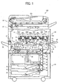
- FIG. 1 illustrates a schematic configuration of an image forming apparatus 100 according to a first exemplary embodiment.
- the image forming apparatus 100 may be a copier, a printer, a facsimile, and a multi-functional apparatus, for example.
- the image forming apparatus 100 conducts an image forming process using image data received from an external device, such a personal computer.
- the image forming apparatus 100 can produce full-color image, for example.
- the image forming apparatus 100 can use a recording medium in sheet form, such as for example plain paper, OHP (overhead projector) sheet, heavy paper (e.g., card, postcard), envelope or the like.
- a recording medium in sheet form such as for example plain paper, OHP (overhead projector) sheet, heavy paper (e.g., card, postcard), envelope or the like.
- the image forming apparatus 100 can record images on both face of the recording medium.
- the image forming apparatus 100 includes a printing unit 101, a sheet feed unit 23, a scanner 21, and an automatic document feeder (ADF) 22, for example.
- the printing unit 101 may be placed over the sheet feed unit 23, the scanner 300 may be placed on the printing unit 101, and the ADF 22 may be placed on the scanner 21, for example.
- the ADF 22 feeds document to the scanner 21.
- the sheet feed unit 23 stores sheets to be transported to the printing unit 101.
- the printing unit 101 may include an image forming unit 60, which includes a plurality of photoconductor drums 20Y, 20M, 20C, and 20K for forming images of yellow(Y), magenta(M), cyan(C), and black(K), respectively.
- Y, M, C, and K represent yellow, cyan, magenta, and black, respectively.
- the image forming apparatus 100 uses the photoconductor drums 20Y, 20M, 20C, and 20K as image bearing members arranged in a tandem manner.
- the photoconductor drums 20Y, 20M, 20C, and 20K, having a same diameter, are aligned along a face of an intermediate transfer belt 11 with a same interval.
- the intermediate transfer belt 11 is disposed under the image forming unit 60, for example, and has endless belt shape.
- the intermediate transfer belt 11 may travel in a clockwise direction shown by an arrow A1 in FIG. 1 .
- Toner images formed on each of the photoconductor drums 20Y, 20M, 20C, and 20K are superimposingly transferred to the intermediate transfer belt 11 moving in the direction shown by an arrow A1 as a full color image, and the full color image is transferred to a sheet.
- the full color image is formed by way of indirect transfer method.
- Toner images can be transferred and superimposed on the intermediate transfer belt 11 as follows: When the intermediate transfer belt 11 moves in the A1 direction, the toner images formed on the photoconductor drums 20Y, 20M, 20C, and 20K are superimposingly transferred on a same position on the intermediate transfer belt 11. Specifically, primary transfer rollers 12Y, 12M, 12C, and 12K, disposed against the photoconductor drums 20Y, 20M, 20C, and 20K via the intermediate transfer belt 11, apply given voltage to transfer the toner images from the photoconductor drums 20Y, 20M, 20C, and 20K to the intermediate transfer belt 11, in which the transfer process for each of the colors are conducted by setting a given time interval.
- the intermediate transfer belt 11 can be manufactured with any methods and materials.
- the intermediate transfer belt 11 can be made from polyimide resin having a good level of strength with following steps: Carbon black is dispersed in polyamic acid solution, and the dispersion solution is poured in a metal drum and dried; the dried material is separated from the metal drum and elongated under a higher temperature condition to form a polyimide resin film; the polyimide resin film is cut in a given size for preparing an endless belt of polyimide resin.
- Such a typical film forming method may be conducted by dispersing carbon black in a polymer solution, pouring the solution in a cylindrical die, heating the materials under 100 to 200 degrees Celcius while the cylindrical die is rotated, and forming a film using centrifugal force.
- the semi-hardened film is separated from the cylindrical die and set on an iron core, and hardened at 300 to 450 degrees Celcius to progress a reaction of obtaining polyimide resin, which becomes the intermediate transfer belt 11.
- Property of the intermediate transfer belt 11 can be adjusted by changing conditions, such as carbon amount, baking temperature, curing rate, by which volume resistivity and surface resistivity can be adjusted.
- the volume resistivity and surface resistivity can be measured by using a highly precise resistivity meter of Hiresta UP (MCP-HT450) and URA probe (MCP-HTP14), both of products of Mitsubishi Chemical Corporation, for example.
- MCP-HT450 Hiresta UP
- MCP-HTP14 URA probe
- the image forming unit 60 includes image forming engines 60Y, 60M, 60C, and 60K, in which each of the photoconductor drums 20Y, 20M, 20C, and 20K are included.
- the image forming apparatus 100 further includes a transfer belt unit 10, which includes the intermediate transfer belt 11 disposed under the photoconductor drums 20Y, 20M, 20C, and 20K.
- the transfer belt unit 10 is used as an intermediate transfer unit.
- the image, forming apparatus 100 further includes a secondary transfer roller 17, a sheet transport unit 76, and a transfer belt cleaning unit 14.
- the secondary transfer roller 17, contacted against the intermediate transfer belt 11, rotates in a same direction with the intermediate transfer belt 11 at the contact portion, at which a toner image is transferred from the intermediate transfer belt 11 to a sheet.
- the secondary transfer roller 17 is used as a second transfer device.
- the sheet transport unit 76 transports the sheet having the toner image transferred from the intermediate transfer belt 11.
- the transfer belt cleaning unit 14, facing the intermediate transfer belt 11, cleans the intermediate transfer belt 11 after the toner image is transferred to the sheet.
- the image forming apparatus 100 further includes an optical writing unit 8, disposed over the image forming engines 60Y, 60M, 60C, and 60K.
- the image forming apparatus 100 further includes registration roller(s) 13, which stops a sheet transported from the sheet feed unit 23 and feeds the sheet to a transfer nip between the intermediate transfer belt 11 and the secondary transfer roller 17 when toner images formed by the image forming engines 60Y, 60M, 60C, and 60K are transferred to the intermediate transfer belt 11.
- the image forming apparatus 100 further includes a sensor to detect that an edge of the sheet reaches the registration roller(s) 13.
- the image forming apparatus 100 further includes a fixing unit 6, which fixes the toner image on the sheet transported by the sheet transport unit 76.
- the image forming apparatus 100 further includes a sheet ejection unit 79, and a sheet reverse unit 96.
- the sheet ejection unit 79 includes a sheet ejection path and a sheet reverse path. The sheet is ejected from the printing unit 101 via the sheet ejection path, or transported to the sheet reverse unit 96 via the sheet reverse path.
- the sheet reverse unit 96 reverses the faces of sheet, supplied from the sheet reverse path of the sheet ejection unit 79 by using a switchback process, and then transports the sheet to the registration roller(s) 13 again.
- the image forming apparatus 100 further includes an ejection tray 75, a manual sheet-feed unit 33, an operation panel, and a control unit.
- the ejection tray 75 stacks sheets ejected from the printing unit 101 after an image forming process.
- the manual sheet-feed unit 33 may be disposed on one side of the printing unit 101 as shown in FIG. 1 .
- the operation panel is used to operate the image forming apparatus 100.
- the control unit controls the image forming apparatus 100 as a whole.
- the transfer belt unit 10 includes the intermediate transfer belt 11, the primary transfer rollers 12Y, 12M, 12C, and 12K, the intermediate transfer belt 11, a drive roller 72, a transfer nip roller 73, and a tension roller 74, and a drive unit.
- the intermediate transfer belt 11 may be extended by the drive roller 72, the transfer nip roller 73, and the tension roller 74.
- the drive unit can pivot the transfer belt unit 10 about the drive roller 72 in a counter-clockwise direction in FIG. 1 , by which the photoconductor drums 20Y, 20M, and 20C can be separated from the intermediate transfer belt 11 while the photoconductor drum 20K is still contacted against the intermediate transfer belt 11.
- the drive unit can be controlled by the control unit.
- FIG. 1 shows a state that a full color image forming is conducted.
- the photoconductor drums 20Y, 20M, and 20C are separated from the intermediate transfer belt 11.
- the image forming apparatus 100 includes the transfer belt cleaning unit 14. Accordingly, after the single black color image forming, black toner can be removed by the transfer belt cleaning unit 14, and thereby black toner may not contaminate the photoconductor drums 20Y, 20M, and 20C. Therefore, the photoconductor drums 20Y, 20M, and 20C may not need to be separated from the intermediate transfer belt 11. However, the photoconductor drums 20Y, 20M, and 20C may be separated from the intermediate transfer belt 11 just in case that the transfer belt cleaning unit 14 cannot remove black toner completely from the transfer belt cleaning unit 14 when the single black color image forming is conducted. Because black toner is so visible, if black toner adheres the photoconductor drums 20Y, 20M, and 20C, the image quality may degrade.
- the photoconductor drum 20K may be disposed at the most downstream of the A1 direction relative to the photoconductor drums 20Y, 20M, and 20C.
- the intermediate transfer belt 11 is contacted against the photoconductor drums 20Y, 20M, 20C, and 20K.
- the photoconductor drum 20K may be disposed at the most downstream of the A1 direction relative to the photoconductor drums 20Y, 20M, and 20C to decrease or prevent black toner contamination to the photoconductor drums 20Y, 20M, and 20C.
- the black toner image is transferred to the intermediate transfer belt 11 after all other toner images are transferred to the intermediate transfer belt 11.
- black toner may not contaminate the photoconductor drums 20Y, 20M, and 20C via the intermediate transfer belt 11.
- the registration roller(s) 13 may be earthed.
- the image forming apparatus 100 using an intermediate transfer method paper powders may not be transported to the photoconductor drums 20Y, 20M, 20C, and 20K. Accordingly, paper powders transfer phenomenon may not be an issue, and thereby the registration roller(s) 13 may be earthed.
- the registration roller(s) 13 may be applied with a bias voltage to remove paper powders of sheet.
- the registration roller 13, having a diameter of 18 mm includes a surface layer made of conductive rubber (e.g., nitrile butadiene rubber (NBR)) of 1 mm thickness, and volume resistance of rubber is about 10 9 Qcm.
- NBR nitrile butadiene rubber
- the registration roller 13 may be applied with DC (direct current) bias voltage, in general. However, the registration roller 13 may be applied with AC (alternative current) voltage including DC (direct current) off-set voltage to uniformly charge the sheet.
- the sheet surface When the registration roller 13 may be applied with DC bias voltage, the sheet surface may be charged to a negative value in small scale. Accordingly, an image transfer from the intermediate transfer belt 11 to the sheet may need a change of image transfer condition compared to when no voltage is applied to the registration roller 13.
- the sheet transport unit 76 includes a transport belt 5, which may be an endless belt for a transporting sheet, and a drive roller 15 and a driven roller 16 extending the transport belt 5.
- the secondary transfer roller 17 faces the transfer nip roller 73 via the intermediate transfer belt 11. Accordingly, the secondary transfer roller 17 and the transfer nip roller 73 may contactingly press the intermediate transfer belt 11.
- the secondary transfer roller 17 may be a non-contact charger.
- the secondary transfer roller 17 may be included in a transfer/transport unit for transferring image and transporting a sheet to the fixing unit 6, in which the secondary transfer roller 17, other roller, and a belt may configure the transfer/transport unit (see 17a in FIG. 6 ).
- the optical writing unit 8 includes a light source, a polygon mirror, a polygon motor, and optical devices, for example.
- the light source emits a laser beam based on image signal to scan a surface of the photoconductor drums 20Y, 20M, 20C, and 20K for writing an electrostatic latent image.
- the polygon mirror rotates to deflect the laser beam used for such scanning.
- the polygon motor drives the polygon mirror.
- the optical devices are used to guide the laser beam deflected by the polygon mirror to the photoconductor drums 20Y, 20M, 20C, and 20B.
- the fixing unit 6 includes a heat roller 62, a pressure roller 63, a fixing belt 64, and a fixing roller 65.
- the heat roller 62 includes a heat source therein.
- the fixing belt 64 is extended by the heat roller 62 and the fixing roller 65.
- the pressure roller 63 applies pressure to the fixing belt 64 with the fixing roller 65.
- the sheet ejection unit 79 includes an ejection roller 97, a transport roller 98, and a switch claw 94.
- the ejection roller 97 ejects sheet outside the printing unit 101.
- the transport roller 98 transports the sheet transported from the fixing unit 6 to the sheet reverse unit 96.
- the switch claw 94 switches the sheet to any one of the sheet ejection path and the sheet reverse path, in which the sheet is ejected outside the printing unit 101 via the sheet ejection path having the ejection roller 97; and the sheet is fed to the sheet reverse unit 96 via the sheet reverse path having the transport roller 98.
- the sheet reverse unit 96 includes a tray 92, a reverse roller 93, a feed roller 95.
- the tray 92 temporarily stacks the sheet transported from the sheet ejection unit 79.
- the reverse roller 93 switchbacks the sheet stuck on the tray 92.
- the feed roller 95 feeds the switch backed sheet to the registration roller 13.
- the sheet feed unit 23 includes a sheet bank 26, a feed roller 24, a separation roller 27, a transport roller 28, and a feed route 29.
- the sheet bank 26 includes sheet cassette(s) 25 storing sheets.
- the feed roller 24 feeds the uppermost sheet of the sheets in the sheet cassette 25.
- the separation roller 27 separates the sheet picked by the feed roller 24 one by one.
- the transport roller 28 transports the sheet, fed by the feed roller 24 and the separation roller 27, to the registration roller 13 through the feed route 29.
- the feed route 29 having the transport roller 28 extends from the sheet feed unit 23 to the printing unit 101.
- the feed roller 24 is rotated in a counter-clockwise direction in FIG. 1 , and the separation roller 27 is activated to feed the sheet into the feed route 29, then the sheet is transported to the registration roller 13 by the rotating transport roller 28, and stopped by the registration roller 13.
- the manual sheet-feed unit 33 includes a manual sheet tray 34, a feed roller 35, a separation roller 36, and a sheet sensor.
- the manual sheet tray 34 is used to stack sheets.
- the feed roller 35 feeds the uppermost sheet of the sheets on the manual sheet tray 34.
- the separation roller 36 separates the sheet picked by the feed roller 35 one by one.
- the sheet sensor detects existence of sheet on the manual sheet tray 34.
- the feed roller 35 is rotated in a clockwise direction in FIG. 1 , and the separation roller 36 is activated to feed the sheet into the feed route 29, then the sheet is transported to the registration roller 13, and stopped by the registration roller 13.
- the scanner 21 includes a contact glass 21a, a first carriage 21b, a second carriage 21c, a focus lens 21d, and an image sensor 21e.
- the first carriage 21b includes a light source for emitting light to the document placed on the contact glass 21a, and a first reflector for reflecting the light reflected on the document.
- the first carriage 21b moves in a horizontal direction in FIG. 1 .
- the second carriage 21c includes a second reflector for reflecting the light reflected by the first reflector of the first carriage 21b.
- the focus lens 21d is used to focus the light coming from the second carriage 21c onto the image sensor 21e, at which image data of document is read.
- the ADF 22 includes a document tray 22a for placing documents.
- the ADF 22 can be pivot about the scanner 21. When the ADF 22 is pivoted upward, the contact glass 21a can be seen.
- a document is set on the document tray 22a of the ADF 22, or a document is set on the contact glass 21a by pivoting the ADF 22 upward and then closing the ADF 22 after setting the document on the contact glass 21a.
- the operation panel includes a start button for starting operations (e.g., copying operation), keys for inputting information such as sheet number for copying operation, a mode key for selecting full color image forming or single black color image forming, for example.
- the control unit includes a CPU (central processing unit), a memory used for information storage, for example.
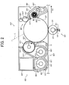
- the image forming engine 60Y includes the photoconductor drum 20Y, a cleaning unit 40Y, a charge unit 30Y, a development unit 50Y, and a de-charge unit, wherein such units surround the photoconductor drum 20Y.
- the primary transfer roller 12Y contacts the intermediate transfer belt 11 and may rotate in one direction in FIG. 2 .
- a pressing unit 18Y presses the primary transfer roller 12Y against the intermediate transfer belt 11 with a given pressure.
- the photoconductor drum 20Y, the cleaning unit 40Y, the charge unit 30Y, the development unit 50Y, and the de-charge unit can be integrated as a process cartridge 95Y, which is detachably mountable to the printing unit 101.
- the process cartridge 95Y can be withdrawn from the printing unit 101 along a guide rail, and can be pushed into the printing unit 101 along the guide rail.
- the process cartridge 95Y can be positioned at a designed position in the printing unit 101 when pushed into the printing unit 101. Such a cartridge configuration can enhance maintenance performance because the process cartridge 95Y can be easily replaced from old one to new one.
- the process cartridge 95Y detachably mountable to the printing unit 101 may include the photoconductor drum 20Y and the development unit 50Y at least.
- the process cartridge 95Y may further include any of the cleaning unit 40Y,'the charge unit 30Y, the development unit 50Y, and the de-charge unit, as required.
- the charge unit 30Y includes a charge roller 31Y, and a cleaning roller 32Y.
- the charge roller 31Y may contact the surface of the photoconductor drum 20Y, and can rotate when the photoconductor drum 20Y rotates.
- the cleaning roller 32Y may contact the charge roller 31Y and can rotate when the charge roller 31Y rotates.
- the charge roller 31Y may be connected to a voltage application unit, which supplies direct current superimposed with alternative current to the charge roller 31Y.
- the charge roller 31Y may charge the photoconductor drum 20Y to a given polarity and voltage at a charge area of the photoconductor drum 20Y. In such charging process, the charge roller 31Y may conduct de-charging and charging of the photoconductor drum 20Y at a substantially same time.
- the cleaning roller 32Y can clean the charge roller 31Y by rotating with the charge roller 31Y.
- the charge unit 30Y may include a contact roller as such, other configuration can be used.
- a proximity roller or scorotron non-contact type can be used.
- the primary transfer roller 12Y contacts the intermediate transfer belt 11 and presses the intermediate transfer belt 11 to the photoconductor drum 20Y.
- the primary transfer roller 12Y includes a shaft 37Y and an elastic layer formed on the shaft 37Y.
- the primary transfer roller 12Y can rotate about the shaft 37Y, rotate-ably supported in the printing unit 101.
- the primary transfer roller 12Y may include a metal core including the shaft 37Y and an elastic layer coated on the metal core.
- the elastic layer of the primary transfer roller 12Y may have Asker C hardness of 50 degrees or less, for example.
- the primary transfer roller 12Y may be supplied with a given primary transfer voltage by using a bias voltage application unit having a power source and a bias control unit.
- the primary transfer roller 12Y and a pressure spring 19Y may be referred as a pressing unit 18Y as a whole.
- the pressure spring 19Y which is disposed between the shaft 37Y and the printing unit 101, is used to press the shaft 37Y of the primary transfer roller 12Y so as to press the primary transfer roller 12Y to the intermediate transfer belt 11.
- the shaft 37Y may be supported by a supporter disposed in the printing unit 101 so that the shaft 37Y can be moved in a given range by the pressure spring 19Y.
- the pressing unit 18Y presses the primary transfer roller 12Y toward the intermediate transfer belt 11 using the pressure spring 19Y
- the intermediate transfer belt 11 can be contacted against the photoconductor drum 20Y. Accordingly, the pressing unit 18Y presses the intermediate transfer belt 11 against the photoconductor drum 20Y upward in a vertical direction.
- the pressure spring 19Y can press the intermediate transfer belt 11 to the photoconductor drum 20Y with a given pressure, which may be referred as primary transfer process pressure.
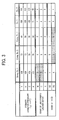
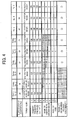
- FIGs. 3 and 4 show such pressure as a primary transfer process pressure, which are used in the experiment to be described later.
- the primary transfer process pressure may be referred as "primary transfer pressure," hereinafter.
- the optical writing unit 8 shown in FIG. 1 irradiates a laser beam L, generated based on image information, onto the photoconductor drum 20Y to write an electrostatic latent image on the surface of the photoconductor drum 20Y charged by the charge roller 31Y.
- the development unit 50Y develops the electrostatic latent image as a yellow toner image.
- the cleaning unit 40Y includes a casing 43Y, a brush roller 45Y, and a cleaning blade 41Y.
- the casing 43Y includes an opening facing the photoconductor drum 20Y.
- the brush roller 45Y contacts the photoconductor drum 20Y to remove residuals such as toner, carrier, and paper powders, from the photoconductor drum 20Y.
- the cleaning blade 41Y contacts the photoconductor drum 20Y at a downstream side of a rotation direction (see B1 in FIG. 2 ) of the photoconductor drum 20Y relative to the brush roller 45Y to remove the residuals from the photoconductor drum 20Y.
- the brush roller 45Y is rotate-ably supported in the casing 43Y.
- the residuals scraped by the brush roller 45Y and the cleaning blade 41Y are transported to a waste toner tank using a screw 42Y or the like.
- the development unit 50Y includes a casing 55Y, a development roller 51Y, and a doctor blade 52Y.
- the casing 55Y includes an opening facing the photoconductor drum 20Y.
- the development roller 51Y faces the photoconductor drum 20Y through the opening.
- the doctor blade 52Y regulates a thickness of developer on the developing roller 51Y at a preferable level for developing process.
- the development unit 50Y further includes a first transport screw 53Y, a second transport screw 54Y, a separation wall 57Y, a first compartment 58Y, and a second compartment 59Y.
- the first transport screw 53Y and the second transport screw 54Y are disposed at a lower part of the casing 55Y side by side, and rotate in opposite directions each other. With such a configuration, developer can be agitated, transported, and supplied to the development roller 51Y.
- the first compartment 58Y including the first transport screw 53Y and the second compartment 59Y including the second transport screw 54Y are separated by the separation wall 57Y.
- the development unit 50Y further includes a toner hopper 80Y, and a toner concentration sensor 56Y.
- the toner hopper 80Y stores yellow toner.
- the toner concentration sensor 56Y disposed at the bottom of the second compartment 59Y, detects toner concentration in the developer.
- the toner concentration sensor 56Y may be attached on the second compartment 59Y using a double-face tape 86Y.
- the development unit 50Y further includes a bias voltage supply unit for supplying a development bias voltage having direct current, a drive unit for driving the development roller 51Y, a transport drive unit for rotating the first transport screw 53Y and the second transport screw 54Y in opposite directions, and a toner supply unit for supplying toner from the toner hopper 80Y to the second compartment 59Y.
- the development roller 51Y includes a magnet roller 81Y, and a development sleave 82Y.
- the magnet roller 81Y generates a magnetic field.
- the development sleeve 82Y made from non-magnetic material and encasing the magnet roller 81Y, can be rotated in a clockwise direction in FIG. 2 (see C1) by the drive unit.
- the magnet roller 81Y includes a plastic casing fixed to the casing 55Y, and a plurality of magnet blocks embedded in the plastic casing to install a plurality of magnetic poles.
- the development sleeve 82Y is rotate-ably supported by the casing 55Y and the magnet roller 81Y.
- the development sleeve 82Y is supplied with a development bias voltage by the bias voltage supply unit.
- a development gap set between the development sleeve 82Y and the photoconductor drum 20Y may be 0.3 ⁇ 0.05 mm, for example.
- the doctor blade 52Y may be made from a stainless steel (SUS).
- a doctor gap set between the development sleeve 82Y and doctor blade 52Y may be 0.5+0.04 mm, for example.
- the developer may be a two-component developer including toner and carrier.
- the carrier may be magnetic carrier, and includes a core material, and a resin layer formed on a surface of the core material.
- the resin layer includes a conductive layer having conductive particles. The detail of toner will be explained later.
- the toner concentration in the developer can be controlled with a given concentration range, such as about 4 to 11 weight %, by the control unit based on a detection result of the toner concentration sensor 56Y so that toner/carrier mixture ratio can be maintained at a preferable level, and thus higher quality images can be obtained.
- a given concentration range such as about 4 to 11 weight %
- toner/carrier mixture ratio can be maintained at a preferable level, and thus higher quality images can be obtained.
- toner concentration sensor 56Y detects that the toner concentration becomes lower than the given concentration range due to a consumption of toner by a developing process
- toner is supplied to the second compartment 59Y from the toner hopper 80Y using the toner supply unit.
- the first transport screw 53Y and the second transport screw 54Y extend in an axial direction of the development roller 51Y.
- the first transport screw 53Y transports the developer in the first compartment 58Y in one direction, and supplies the developer to the development roller 51Y during such transportation.
- Developer transported to a downstream end of the first compartment 58Y by the first transport screw 53Y is then guided into the second compartment 59Y through an opening of the separation wall 57Y.
- the second transport screw 54Y transports the developer in the opposite direction of the first transport screw 53Y. If the toner hopper 80Y supplies fresh toner, the fresh toner is mixed and transported with the developer by the second transport screw 54Y. Developer transported to a downstream end of the second compartment 59Y by the second transport screw 54Y is then guided into the first compartment 58Y through the other opening of the separation wall 57Y.
- the fresh toner can be agitated and transported with developer by the first transport screw 53Y and the second transport screw 54Y, by which the developer can be frictionally electrified and then supplied to the development roller 51Y.
- the development roller 51Y transports the developer to a developing area set between the development roller 51Y and the photoconductor drum 20Y.
- yellow toner in the developer can be electrostatically transferred to a latent image formed on the photoconductor drum 20Y, by which a yellow toner image can be developed on the development roller 51Y.
- the developer consumed of yellow toner is returned to the development unit 50Y by a rotation of the development roller 51Y.
- the bias voltage supply unit supplies a development bias voltage having direct current
- the bias voltage supply unit can supply other development bias voltage, such as a bias voltage of alternative current or a bias voltage having superimposed alternative current to direct current.
- the developer in the development unit 50Y, the developer can be agitated and transported by the first transport screw 53Y and the second transport screw 54Y, and can be attracted and carried on the development sleeve 82Y by magnet force. Then, the developer is transported to the developing area facing the photoconductor drum 20Y, and toner is supplied to the latent image on the photoconductor drum 20Y for developing the toner image.
- the toner-consumed developer is returned to the first compartment 58Y from the development sleeve 82Y by a rotation of the development roller 51Y, and then agitated and transported again by the first transport screw 53Y and the second transport screw 54Y in the first compartment 58Y and the second compartment 59Y, and again the developer can be attracted and carried on the development sleeve 82Y.
- Such a developer delivery cycle can be conducted by arranging the magnet blocks in a given order.
- toner in the developer may be consumed, by which toner concentration decreases.
- Such toner concentration decrease can be detected by the toner concentration sensor 56Y.
- the toner concentration sensor 56Y detects toner concentration by measuring magnetic permeability of the developer, wherein magnetic permeability of the developer can be detected as detection voltage "Vout” output from the toner concentration sensor 56Y.
- the toner concentration sensor 56Y outputs a detection voltage "Vout” as a detected toner concentration signal to the control unit, and toner concentration is determined as "weight %" based on a value of the detection voltage Vout.
- the lower the toner concentration TC the higher the magnetic permeability because carrier ratio becomes higher; and the higher the toner concentration TC, the lower the magnetic permeability because carrier ratio becomes lower. Accordingly, the lower the toner concentration TC, the higher the detection voltage Vout (or the toner concentration TC and the detection voltage Vout is inversely related).
- control unit when the control unit recognizes a lower toner concentration based on the detection voltage Vout from the toner concentration sensor 56Y, the control unit activates the toner supply unit to supply toner to the second compartment 59Y from the toner hopper 80Y until the detection voltage Vout becomes a given level.
- a document is set on the document tray 22a of the ADF 22, or a document is set on the contact glass 21a by pivoting the ADF 22 upward and then closing the ADF 22 after setting the document on the contact glass 21a. Then a start button in the operation panel is pressed for starting a copying operation.
- the image forming apparatus 100 When the image forming apparatus 100 is used as a printer the image forming apparatus 100 conducts an image forming process using image data received from an external device, such as a personal computer, which is used to select and input the image data for image forming operation.
- the document When the document is set on the ADF 22, the document is fed to the contact glass 21a by pressing the start button, and then the document is scanned by the scanner 21 to generate image data.
- the document When the document is set on the contact glass 21a, the document is scanned by pressing the start button to generate image data.
- the scanner 21 includes the first carriage 21b and the second carriage 21c, which can move in a given direction when scanning a document.
- the light source of the first carriage 21b emits light to the document placed on the contact glass 21a, and then the first reflector reflects the light reflected on the document to the second reflector of the second carriage 21c. Then the light is reflected by the second reflector and guided to the focus lens 21d.
- the focus lens 21d focuses the light coming from the second carriage 21c onto the image sensor 21e, at which image data of the document is read.
- the image forming engines 60Y, 60M, 60C, and 60K can be activated.
- the photoconductor drum 20Y rotating in the B1 direction is uniformly charged by the charge roller 31Y, and then irradiated by the laser beam L coming from the optical writing unit 8 to form an electrostatic latent image for yellow.
- the electrostatic latent image is then developed by the development unit 50Y as a yellow toner image.
- the yellow toner image is then transferred to the intermediate transfer belt 11 moving in the A1 direction using the primary transfer roller 12Y.
- the cleaning unit 40Y removes residual materials, such as toner, remaining on the photoconductor drum 20Y, and the de-charge unit de-charges the photoconductor drum 20Y to prepare the photoconductor drum 20Y for an next image forming process.
- toner images are formed on the photoconductor drums 20C, 20M and 20K, and then the toner images are transferred onto the intermediate transfer belt 11 moving in the A1 direction using the primary transfer rollers 12C, 12M, and 12K to form a full color image.
- the full color image is then transported to a transfer nip set by the intermediate transfer belt 11 and the secondary transfer roller 17, and transferred to a sheet.
- the sheet transported to the transfer nip set by the intermediate transfer belt 11 and the secondary transfer roller 17 may be fed from the sheet cassette 25, the manual sheet tray 34, or the sheet reverse unit 96, for example.
- the sheet is fed to the transfer nip by the registration roller 13 at a time that the toner images on the intermediate transfer belt 11 comes to the transfer nip facing the secondary transfer roller 17.
- the sheet having the toner images is then transported to the fixing unit 6 by the sheet transport unit 76, at which the toner images are fixed on the sheet by applying heat and pressure to the sheet using the fixing belt 64 and the pressure roller 63, by which a color image is formed on the sheet.
- the sheet After passing the fixing unit 6, by adjusting a position of the switch claw 94, the sheet may be stacked on the ejection tray 75 using the ejection roller 97 or may be sent to the sheet reverse unit 96 by the transport roller 98 for double face printing.
- the transfer belt cleaning unit removes residual materials, such as toner, remaining on the intermediate transfer belt 11 to prepare the intermediate transfer belt 11 for an next image forming process.
- toner according to exemplary embodiments, which is used as two-component developer in the image forming apparatus 100.
- the toner can be manufactured with any methods, and any binder resin and colorant as long as such materials are within conditions set for exemplary embodiments.
- Example of the binder resin include polyester resin, styrene resin, acrylic resin, styrene-acrylic resin, polyol resin, epoxy resin. Specifically, polyester resin is preferably used from a viewpoint of low-temperature fixability.
- a glass-transition temperature "Tg" of the binder resin is preferably from 40 to 75 degrees Celcius, and more preferably from 45 to 65 degrees Celcius. If the glass-transition temperature is too low, thermostable preservability of toner may be degraded, and toner particles may be easily subjected to a blocking phenomenon at a higher temperature, which is not preferable. If the glass-transition temperature is too high, low-temperature fixability of the toner may deteriorate.
- the glass-transition temperature Tg can be measured using a differential scanning calorimeter (DSC).
- DSC differential scanning calorimeter
- the temperature Tg is measured from a DSC profile obtained by using DSC-60A (product of SHIMADZU CORPORATION) with a condition of temperature rising speed of 10 Degrees Celcius/min.
- colorant such as pigment and dye can be used as a colorant for the toner.
- colorant include carbon black, nigrosin dye, naphthol yellow, Hansa yellow, ployazo yellow, oil yellow, pigment yellow, permanent yellow, brilliant carmine, permanent red, oil red, quinacridone red, pyrazolone red, ployazo red, phthalocyanine blue, anthraquinone blue, anthraquinone violet, naphthol green, and phthalocyanine green. These can be used alone or in combination.
- the colorant may be included in toner matrix from 0.5 to 15 weight percent %, and preferably from 3 to 10 weight percent %, for example.
- the toner matrix is toner composition before adding additives (i.e., additives are not included).
- the colorant can be prepared as master batch by mixing resin and colorant.
- the resin used for master batch may be the resin used for the binder resin of toner, but not limited these.
- the toner particles may preferably include a release agent in addition to the binder resin and the colorant.
- a release agent examples include polyolefin wax (e.g., polyethylene wax, polypropylene wax); long-chain hydrocarbon (e.g., paraffin wax, southall wax); and carnauba wax, montan wax.
- the release agent may be included in toner matrix from 0 to 40 weight percent %, and preferably from 5 to 20 weight percent %.
- toner particles may include a charge control agent to enhance charge amount and charging speed of toner particles, as required.
- the charge control agent include nigrosine dye, triphenylmethane dye, chromium containing metal-complex compound dye, chelate molybdate pigment, quaternary ammonium salt, fluorine modified quaternary ammonium salt, salicylic acid metal salt, and metal salt of salicylic acid derivative.
- the adding amount of the charge control agent is determined based on toner manufacturing condition such as types of binder resins, presence or absence of additives, and a dispersion method, or the like.
- the charge control agent may be included in toner matrix from 0.1 to 10 weight percent %, and preferably from 0.2 to 5 weight percent %.
- the charge control agent can be dispersed in toner, externally added to toner surface, or fixed on toner surface, for example.
- inorganic fine particles may be preferably used as external additives to facilitate fluidity, developing performance, charged performance of toner particles.
- Such inorganic fine particles preferably have a primary particle diameter of 5 nm (nanometer) to 2 ⁇ m.
- Such inorganic fine particles are preferably added to the toner particles with 0.01 wt%, to 5 wt%.
- inorganic fine particles examples include silica, alumina, titanium oxide, barium titanate, magnesium titanate, calcium titanate, strontium titanate, zinc oxide, tin oxide, silica sand, clay, mica isinglass, sand-lime, diatomite, chrome oxide, cerium oxide, colcothar, antimony trioxide, magnesium oxide, zirconium oxide, barium sulfate, barium carbonate, calcium carbonate, silicon carbide, and silicon nitride. These can be used alone or in combination.
- the toner used in the image forming apparatus 100 preferably includes polyester resin, prepared by an ester elongation polymerization method and having good level of low-temperature fixability, as the binder resin.
- toner made from resin powders has been prepared by setting a lower softening point.
- Such toner can be prepared using a soft resin, for example polyester resin, as a binder resin of toner.
- the ester elongation polymerization method is conducted as follows to prepare toner particles: An organic solvent containing polyester prepolymer is dispersed with compound having active hydrogen in an aqueous solvent; in the aqueous solvent, elongation reaction and/or cross-linking reaction is progressed; then remove the organic solvent; and wash and dry to obtain the resultant product as toner particles.
- Such method can easily control particle diameter, particle size distribution, and shape of toner.
- the method and used materials are described.
- the polyester prepolymer is reacted with compound having active hydrogen in the aqueous solvent (i.e., elongation reaction and/or cross-linking reaction) to form molecules having a larger molecular weight as binding resin of toner.
- the polyester prepolymer may have functional groups, such as for example isocyanate group, which can react with active hydrogen.
- polyester prepolymer having isocyanate group is preferably used as polyester prepolymer.
- Such polyester prepolymer can be prepared by reacting polyester having active hydrogen group and polyisocyanate (PIC), wherein the polyester is a polycondensation product of polyol (PO) and polycarboxylic acid (PC).
- the polycondensation product having active hydrogen group made from polyol (PO) and polycarboxylic acid (PC) may be prepared using bisphenol-A alkyleneoxide adduct and polycarboxylic acid, for example.
- the polycarboxylic acid include dicarboxylic acid (e.g., succinic acid, adipic acid, maleic acid, fumaric acid, phthalic acid, terephthalic acid), and tirvalent or more polycarboxylic acid having trivalent or more (e.g., trimellitic acid, pyromellitic acid).
- polyisocyanate examples include aliphatic polyisocyanate (e.g., tetramethylene diisocyanate, hexamethylene diisocyanate, 2,6-diisocyanate methyl caproate); alicyclic polyisocyanate (e.g., isophorone diisocyanate, cyclohexylmethane diisocyanate); aromatic diisocyanate (e.g., tolylene diisocyanate, diphenylmethane diisocyanate); aromatic aliphatic diisocyanate (e.g., ⁇ , ⁇ , ⁇ ', ⁇ '-tetramethylxylylene diisocyanate); isocyanates; and compounds formed by blocking the polyisocyanate with phenol derivative, oxime, or caprolactam. These can be used alone or in combination.
- aliphatic polyisocyanate e.g., tetramethylene diisocyanate, hexamethylene diisocyan
- the number of isocyanate group contained in one molecule of the polyester prepolymer having isocyanate group is at least 1, preferably at an average of 1.5 to 3, and more preferably at an average of 1.8 to 2.5. If the number of isocyanate group per molecule is less than 1, the molecular weight of polyester after the elongation reaction becomes lower, by which hot offset resistance may be degraded.
- the polyester prepolymer is used by dissolving in organic solvent phase as above described.
- the polyester prepolymer may be included in toner matrix from 10 to 55 weight percent %, preferably 10 to 40 weight percent %, and more preferably from 15 to 30 weight percent %.
- non-reactive polyester can be used with the polyester prepolymer by dissolving in organic solvent phase.
- non-reactive polyester low-temperature fixability of toner and glossiness of color image can be enhanced compared to using the polyester prepolymer alone.
- the non-reactive polyester may be a polycondensation product of the polyol and the polycarboxylic acid as similar to the above described polyester prepolymer, to be reacted with the polyisocyanate (PIC), and the non-reactive polyester may be made from the above-mentioned polyol and polycarboxylic acid.
- PIC polyisocyanate
- a weight ratio of the polyester prepolymer and the non-reactive polyester is from 10/90 to 55/45, preferably from 10/90 to 40/60, more preferably from 15/85 to 30/70. If the weight ratio of polyester prepolymer is too small, hot offset resistance may be degraded, and a compatibility of thermostable preservability of the toner and low-temperature fixability of the toner may deteriorate.
- resin other than the non-reactive polyester can be used.
- known toner binder resin such as styrene resin, acrylic resin, epoxy resin, copolymer of styrene acrylic ester can be added.
- Examples of compound having active hydrogen may be preferably amines.
- the amines react with the isocyanate group of the polyester prepolymer to obtain urea-modified polyester resin.
- amines include diamine, trivalent or more polyamine, amino alcohol, amino mercaptan, amino acid, and these amine compound having blocked amino group.
- the compound having blocked amino group may be ketimine compound, in which amino group of amine compound is blocked by ketone: such amine compound may be 4,4'-diaminodiphenylmethane, isophorone diamine, hexamethylene diamine, ethanolamine, amino ethyl mercaptan, amino propionic acid; and ketone may be methyl ethyl ketone.
- the colorant or colorant master batch may be preferably solved or dispersed in the organic solvent phase with the polyester prepolymer and the non-reactive polyester in advance. Further, the release agent and charge control agent may be also solved or dispersed in the organic solvent phase, as required.
- the aqueous solvent may be composed water alone, but the aqueous solvent may be composed water and organic solvent. Specifically, such organic solvent added in aqueous solvent may preferably solve the resin composition in the organic solvent phase so that the viscosity of resin composition contained in the organic solvent can be decreased when the resin composition is dispersed in the aqueous solvent. Such organic solvent may be preferably volatile at less than 100 Degrees Celcius so that the organic solvent can be removed easily.
- organic solvent in the aqueous solvent examples include toluene, xylene, benzene, tetrachloride carbon, dichloromethane, 1,2-dichloroethane, 1,1,2-trichloroethane, trichloroethylene, chloroform, monochlorobenzene, dichloroethylidene, methyl acetate, acetic ether, methyl ethyl ketone, and methyl isobutyl ketone. These can be used alone or in combination.
- fine resin particles may be preferably dispersed in the aqueous solvent during a toner manufacturing process. Such fine resin particles may be used to control toner shape factors, such as for example sphericity, particle size distribution, and may be locally added on surfaces of the toner particles to be formed.
- the fine resin particles include vinyl resin, polyurethane resin, epoxy resin, polyester resin, polyamide resin, polyimide resin, silicone resin, phenol resin, melamine resin, urea resin, aniline resin, ionomer resin, and polycarbonate resin. These can be used alone or in combination.
- vinyl resin, polyurethane resin, epoxy resin, polyester resin or combination of these are preferably used to obtain spherical fine particles in an aqueous dispersion.
- vinyl resin examples include homopolymer or copolymer of vinyl monomers, and may be copolymer of styrene (meth)acrylic acid ester, copolymer of styrene/butadiene, copolymer of (meth)acrylic acid-acrylic acid ester, copolymer of styrene/acrylonitrile, copolymer of styrenemaleic anhydride, and copolymer of styrene (meth)acrylic acid.
- styrene (meth)acrylic acid ester copolymer of styrene/butadiene
- copolymer of (meth)acrylic acid-acrylic acid ester copolymer of styrene/acrylonitrile
- copolymer of styrenemaleic anhydride copolymer of styrene (meth)acrylic acid.
- the amount of such fine resin particles in the aqueous solvent is preferably from 0.5 to 10 weight %, and more preferably from 1 to 3 weight % with respect to the organic solvent phase. If the amount of fine resin particles is not within such range, emulsification may be failed, by which toner particles may not be formed.
- the fine resin particles may have an average particle diameter from 5 nm to 200 nm, and more preferably from 20 nm to 300 nm from a viewpoint of toner particles formation.
- a glass-transition temperature "Tg" of the fine resin particles is preferably from 40 to 90 degrees Celcius, and more preferably from 50 to 70 degrees Celcius from a viewpoint of low-temperature fixability and thermostable preservability of the toner.
- the weight average particle diameter (D4), number average particle diameter (D1), and particle diameter distribution of a toner can be measured using an instrument COULTER COUNTER TA-II or COULETR MULTISIZER II from Coulter Electrons Inc.
- the typical measuring method is as follows:
- the channels include 13 channels as follows: from 2.00 to less than 2.52 ⁇ m; from 2.52 to less than 3.17 ⁇ m; from 3.17 to less than 4.00 ⁇ m; from 4.00 to less than 5.04 ⁇ m; from 5.04 to less than 6.35 ⁇ m; from 6.35 to less than 8.00 ⁇ m; from 8.00 to less than 10.08 ⁇ m; from 10.08 to less than 12.70 ⁇ m; from 12.70 to less than 16.00 ⁇ m; from 16.00 to less than 20.20 ⁇ m; from 20.20 to less than 25.40 ⁇ m; from 25.40 to less than 32.00 ⁇ m; and from 32.00 to less than 40.30 ⁇ m. Namely, particles having a particle diameter of from not less than 2.00 ⁇ m to less than 40.30 ⁇ m can be measured.
- the degree of sphericity SR of particles can be measured by using a flow-type particle image analyzing apparatus FPIA-2000 produced by Toa Medical Electronics Co., Ltd, and an analysis program (FPIA-2100 Data Processing Program for FPIA version 01-10) is used for analysis. Such measuring may be conducted as below.
- 0.1-0.5 ml of 10 wt % surfactant preferably alkyl benzene sulfonate (neogen SC-A, product of Daiichi Kogyo Seiyaku Co., Ltd.), used as a dispersing agent is place in a 100 ml glass container, and about 0.1-0.5 g of measurement sample (i.e., toner) is further added thereto and mixed using a micro spatula. Then 80 ml of ion-exchange water is added.
- 10 wt % surfactant preferably alkyl benzene sulfonate (neogen SC-A, product of Daiichi Kogyo Seiyaku Co., Ltd.)
- measurement sample i.e., toner
- an ultrasonic wave is applied to a suspension having a sample dispersed therein for 3 minute using an ultrasonic dispersing machine (product of Honda Electronics Co., Ltd.) to set a suspension dispersion density as 5,000-15,000 particles/ ⁇ l, and the shape of a toner particles and distribution of the degree of sphericity of toner particles are measured by using the above-mentioned flow-type particle image measuring apparatus FPIA-2100.
- the suspension dispersion density may be set to 5,000-15,000 particles/ ⁇ l so that the average sphericity of toner can be measured reliably.
- Such suspension dispersion density can be determined based on the condition of dispersion liquid, which means the amount of surfactant and toner needs to be changed as required.
- the amount of surfactant may be adjusted depending on hydrophobicity of toner. If the amount of surfactant is too large, noise due to bubble may be counted, and if the amount of surfactant is too small, toner may not be wetted effectively, by which toner may not be dispersed effectively.
- the amount of toner may be changed based on particle diameter of toner. If the toner has small diameter particle, the amount of toner may be set small, and if the toner has large particle diameter, the amount of toner may be set large. If the toner has a particle diameter of 3 ⁇ m to 7 ⁇ m, 0.1 to 0.5 gram of toner may be added to set the suspension dispersion density from 5,000-15,000 particles/ ⁇ l.
- additives may easily sink into toner particle.
- Such sinking phenomenon of additives may affect transfer performance of toner.
- an index indicating sinking degree of additives into toner is devised as "sunken rate of additives.” The sunken rate of additives is described hereinafter.
- the sunken rate of additives indicates sunken degree of additives, added on toner surface and later sunk in toner particle, which is sunk due to agitation stress in a development unit over time.
- the sunken rate of additives X(%) is set higher (e.g., 40% or more), such toner may be a softer toner having a lower melting point, by which toner can be fixed at a lower temperature, and the fixability of toner and energy saving can be compatibility balanced.
- the sunken rate of additives X(%) is set too high, additives may sink in toner in greater degree, by which transferability of toner may be decreased and unintended uneven image may occur.
- the sunken rate of additives X(%) needs to be set to a value which can compatibility balance the fixability and transferability of the toner image.
- the fixability and transferability of the toner image can be balanced by setting the sunken rate of additives X(%) at a given value and by setting the primary transfer pressure at a given value, which will be descried later.
- the sinking process of additives can be conducted as below.
- the BET specific surface of toner before additives sinking process and after additives sinking process is measured using automatic specific surface/pore distribution analyzer TriStar 3000 (product of SHIMADZU CORPORATION). Specifically, 1g of toner is placed in a measurement cell. A deaeration process is conducted to the measurement cell using a deaeration unit of Vacu-prep 061 (product of SHIMADZU CORPORATION) devised for the TriStar. The deaeration process is conducted under ambient temperature and reduced pressure of 100 mtorr for 20 hours. After the deaeration process, BET specific surface for sample in the measurement cell is measured automatically using TriStar 3000. The deaeration process uses nitrogen gas as absorption gas.
- the toner according to exemplary embodiments may have a sunken rate of additives of 42%, for examples.
- Such toner can be prepared as below.
- the aqueous solvent dispersion liquid was put and the solvent was removed under 30 degrees Celcius for 12 hours. Then, the liquid was heated to 45 degrees Celcius for 8 hours, by which a dispersion liquid removing organic solvent was obtained.
- a resultant cake was added with 500 part of ion-exchange water, and mixed for 10 minutes using the TK homomixer (rotating at 12,000 rpm), and filtered again under a reduced pressure.
- the resultant cake was dried at 45 degrees Celcius for 48 hours using a circulating wind drier.
- the dried cake was filtered using a 75- ⁇ m mesh to obtain toner matrix to be used for toner particles.
- the toner matrix of 100 weight part were mixed with external additives using Henschel Mixer:
- the used external additives were 1.2 weight part of hydrophobicity silica (product of Clariant(Japan)K.K.) having an average primary particle diameter of 12 nm, 0.5 weight part of hydrophobicity titanium oxide (product of Tayca Corporation) having an average primary particle diameter of 12 nm, and 0.8 weight part of hydrophobicity silica (Shin-Etsu Chemical Co., Ltd.) having an average primary particle diameter of 120 nm.
- the mixture was filtered using a 38- ⁇ m mesh to obtain toner particles.
- the obtained toner had a weight-average particle diameter (D4) of 5.8 ⁇ m, a number-average particle diameter (Dn) of 5.1 ⁇ m, an average sphericity of 0.97, and a sunken rate of additives of 42%.
- the weight-average particle diameter (D4) and the number-average particle diameter (Dn) were measured using the above-described procedure.
- the sunken rate of additives can be adjusted by changing molecular weight of resin. For example, if polyester resin (RS801, product of Sanyo Chemical Industries, Ltd., weight-average molecular weight: 19000, Tg: 64 degrees Celcius) is changed to polyester resin (product of Sanyo Chemical Industries, Ltd., weight-average molecular weight: 12000, Tg: 56 degrees Celcius), toner having a weight average particle diameter (D4) of 5.7 ⁇ m, a number-average particle diameter (Dn) of 5.1 ⁇ m, an average sphericity of 0.98, and a sunken rate of additives of 56% was obtained. Further, when styrene-acrylic resin was used, toner having a sunken rate of additives of 30% was obtained.
- polyester resin RS801, product of Sanyo Chemical Industries, Ltd., weight-average molecular weight: 19000, Tg: 64 degrees Celcius
- polyester resin product of Sanyo Chemical Industries, Ltd., weight-average molecular weight
- the toner image when transferring a toner image from the image bearing member to the intermediate transfer medium, or from the intermediate transfer medium to the sheet, the toner image should be transferred to a transfer member in a manner that the image is correctly and stably transferred at a primary transfer process.
- Such correct and stable transfer at the primary transfer process can be conducted by adjusting the primary transfer pressure, which is used to press the intermediate transfer medium to the image bearing member.
- the primary transfer pressure cause some effect to a secondary transfer performance.
- the primary transfer pressure can be adjusted by changing pressure of the pressure spring 19 (19Y, 19M, 19C, and 19K), which presses the intermediate transfer belt 11 to the photoconductor drum 20 (20Y, 20M, 20C, and 20K).
- the pressure spring 19 is used as a pressing member or device.
- the primary transfer pressure is a pressure that the primary transfer rollers 12Y, 12M, 12C, and 12K press the intermediate transfer belt 11.
- the primary transfer pressure can be computed by subtracting self-weight of the primary transfer rollers 12 (12Y, 12M, 12C, and 12K) from the pressure value of the pressure spring 19 (19Y, 19M, 19C, and 19K), for example.
- the primary transfer roller 12 including an elastic layer has an Asker C hardness of 50 degrees or less, by which the primary transfer roller 12 can be deformed easily when the primary transfer pressure is applied, and thereby the primary transfer roller 12 can contact the intermediate transfer belt 11 with a greater contact area.
- the primary transfer roller 12 even if imbalance of primary transfer pressure of the primary transfer roller 12 (12Y, 12M, 12C, and 12K) may occur along an axial direction of the primary transfer roller 12 due to some reasons (e.g., variation of tolerance value during assembly), and even if the primary transfer pressure may deviate from an intended pressure for some amount, the primary transfer roller 12 having such hardness can mitigate such effect of pressure variation or deviation. Accordingly, the secondary transfer performance can be conducted at a good level for producing images. Further, under such configuration, the primary transfer pressure can be set to a lower value.
- FIGs. 3 to 5 show experiment results for image forming when the primary transfer pressure is changed.
- “Examples” in FIGs. 3 to 5 include favorable conditions for image forming.
- “Comparative Examples” in FIGs. 3 to 5 include not-favorable conditions for image forming.
- “Example” is abbreviated as “Ex.”
- “Comparative Example” is abbreviated as “Comp. Ex.” in FIGs. 3 to 5 .
- void means an image failure that some image in line edge of a formed image or some image in the center of letter image becomes void.
- unintended uneven image means an image failure that a formed image has some uneven image due to a lower transfer performance, which may occur at some local portion on a transfer member (e.g., transfer belt, sheet).
- a transfer member e.g., transfer belt, sheet.
- unintended uneven image may occur as below: A sheet (e.g., paper) has irregularity (e.g., concavity and convexity) on its surface.
- additives sink in toner such toner may firmly adhere on a transfer member (e.g., intermediate transfer belt), by which toner images may be hard to transfer from the transfer member to a concavity portion of the surface of the sheet even if a given bias voltage is applied at a transfer nip.
- a transfer member e.g., intermediate transfer belt
- FIG. 3 shows evaluation results of "unintended uneven image” and "void” of image when the primary transfer pressure is changed.
- “void” section in FIG. 3 “1C” means a case when single color image is formed (e.g., any one of Y, M, C, and K is formed), and “2C” means a case when two color images are superimposed (e.g., any two of Y, M, C, and K are superimposed).
- Comparative Examples 1 to 3 use conditions that each of the color Y, M, C, K is formed under a same primary transfer pressure.
- the primary transfer pressure for Comparative Example 2 was set smaller than that of Comparative Example 1, and the primary transfer pressure for Comparative Example 3 was set smaller than that of Comparative Example 2.
- Examples 1 and 2 used conditions that the primary transfer pressure for black(K) was set smaller than other colors Y/M/C, in which black image was transferred after all other Y/M/C color images were transferred. Examples 1 and 2 show that "unintended uneven image” rank and "void" rank were in allowable ranks.
- a black image may be formed on a different position relative to positions of other color images on the intermediate transfer belt 11 or a sheet. Accordingly, when a black image and other color image(s) are formed on a same transfer member, two images (i.e., black and other color) may not overlap each other so much. Therefore, "void" may not occur even when two color toner images are superimposed.
- Comparative Example 2 had a slightly better results compared to Example 1
- Comparative Example 3 had a slightly better results compared to Example 2.
- the primary transfer pressure was set smaller for all colors for Comparative Examples 2 and 3, and the primary transfer pressure was set smaller only for black in Examples 1 and 2. Accordingly, Comparative Example 2 and Example 1, and Comparative Example 3 and Example 2 can be compared in terms of whether a smaller primary transfer pressure is set for all colors or a smaller primary transfer pressure is set only for black.
- the toner used for the experiment had a sunken rate of additives of 42%, and the intermediate transfer belt 11 used for the experiment was made from polyimide resin, and had a volume resistivity of 1 ⁇ 10 9 ⁇ •cm and a surface resistivity of 1 ⁇ 10 11 ⁇ / ⁇ .
- FIG. 4 shows another evaluation results for "unintended uneven image” and "void” as similar to FIG. 3 .
- the sunken rate of additives of toner was changed for Examples and Comparative Examples, and toner fixability at low temperature/low humidity was also evaluated as shown in FIG. 4 .
- the circle “O” indicates fixability was in an allowable level
- the cross “X” indicates fixability was not in an allowable level.
- Comparative Examples 4 to 9 used the primary transfer pressure of 100g/cm 2 as similar to Comparative Example 1.
- Comparative Examples 4 to 6 the toner having the, sunken rate of additives of less than 40% was used.
- "void" rank had a similar result as Comparative Example 1, which may be assumed acceptable for practical usage, but the toner fixability at the low temperature/low humidity (e.g., 10 degrees Celcius/15% humidity) was not in the allowable level.
- Comparative Examples 7 to 9 the toner having the sunken rate of additives of 40% or more was used.
- "void" rank was in allowable rank, and toner fixability at the low temperature/low humidity (e.g., 10 degrees Celcius/15% humidity) was in the allowable level.
- "unintended uneven image” rank became lower and in the not-allowable rank.
- Example 3 to 5 the toner having the sunken rate of additives of 40% or more were used and the primary transfer pressure for black was set smaller than other colors.
- “unintended uneven image” rank and “void” rank were in the allowable rank, and toner fixability at the low temperature/low humidity (e.g., 10 degrees Celcius/15% humidity) was also in an allowable level.
- polyester resin as toner biding resin, toner having a lower physical strength, greater sunken rate of additives, and higher fixability at low temperature can be prepared easily.
- the intermediate transfer belt 11 used for the experiment was made from polyimide resin, and had a volume resistivity of 1 ⁇ 10 9 ⁇ •cm and a surface resistivity of 1 ⁇ 10 11 ⁇ / ⁇ .
- FIG. 5 shows results of "unintended uneven image” for an image composed of superimposing two colors selected from Y, M, and C, in which the order of image forming of different colors (Y, M, C, K) is changed.
- "O” indicates that the level of "unintended uneven image” is allowable
- "X” indicates that the level of "unintended uneven image” is not allowable. Images composed of two colors of Y, M, and C were evaluated.
- the order of image forming of different colors (Y, M, C, K) is "YMCK”
- an image forming process is conducted in an order of "yellow (first), magenta (second), cyan (third), and black (last)" on the intermediate transfer belt 11 in its moving direction (A1 in FIG. 1 ) for a primary transfer process.
- FIG. 5 shows that when the order of image forming of different colors (Y, M, C, K) is yellow, magenta, cyan, and black, red/green/blue images composed of two colors of Y, M, and C had allowable level for "unintended uneven image.” This could be explained as below.
- red/green/blue images can be formed as below.
- Red image is formed by forming yellow image at first then magenta image (Red image: yellow is formed first and then magenta is superimposed). Accordingly even if yellow is not formed effectively in some portion, magenta may suppress the effect of not-formed yellow.
- Green image is formed by forming yellow image at first then cyan image (Green image: yellow is formed first and then cyan is superimposed). Accordingly even if yellow is not formed effectively in some portion, cyan may suppress the effect of not-formed yellow.
- Blue image is formed by forming magenta image at first then cyan image (Blue image: magenta is formed first and then cyan is superimposed). Accordingly, even if magenta is not formed effectively in some portion, cyan may suppress the effect of not-formed magenta.
- unintended uneven image may not be so visible, and thereby unintended uneven image may be within an allowable level.
- the image forming process may be preferably conducted by considering difference between colors of Y, M, C, and K. Specifically, the image forming process using a plurality of color images may be preferably conducted in the order of colors from light to dark (or lightest to darkest). Such image forming process conducted from light color to dark color may have other preferable aspects for producing higher quality images.
- disturbance on images caused by a transfer bias voltage may more likely occur for color images at an upstream side of the moving direction of the intermediate transfer belt 11. If the image forming process is conducted in the order from light color to dark color, such disturbance may not be so visible; Further, even if color toner at the upstream side of the moving direction of the intermediate transfer belt 11 may adhere on other image bearing member(s) disposed at the downstream side of the moving direction of the intermediate transfer belt 11, such adhered color toner may not be so visible on the other image bearing member(s). Accordingly, image failure may not become so visible, and thereby an image having higher quality can be preferably formed.
- the toner used for the experiment shown in FIG. 5 had a sunken rate of additives of 42%, and the intermediate transfer belt 11 used for the experiment was made from polyimide resin, and had a volume resistivity of 1 ⁇ 10 9 ⁇ •cm and a surface resistivity of 1 ⁇ 10 11 ⁇ / ⁇ .
- FIG. 6 shows a graph indicating a relationship of BET specific surface of toner matrix and rank of "unintended uneven image" for magenta image using toner of Example 3 in FIG. 4 without changing conditions of sunken rate of additives, toner resin, primary transfer pressure while changing the BET specific surface of toner matrix.
- the unintended uneven image may be affected by BET specific surface of toner matrix.
- toner-to-toner contact or toner-to-transfer member e.g., intermediate transfer belt 11
- adherence of toner-to-toner particle or adherence of toner-to-transfer member becomes weaker because additives may not exist on toner particles so much. Therefore, a transfer performance may not become a sufficient level.
- toner having the sunken rate of additives of 40% or more by setting the primary transfer pressure for black smaller than other colors, and by setting the BET specific surface of toner matrix to 3 m 2 /g or less, unintended uneven image can be prevented more effectively.
- the index for toner shape may include toner sphericity, toner shape factors (e.g., SF-1, SF-2).
- toner shape factors e.g., SF-1, SF-2.
- such indexes are two-dimensional index, which is computed by projecting toner on a two-dimensional plane, and thereby such indexes may indicate two-dimensional concavity and convexity.
- the BET specific surface indicates a surface area of toner, by which three-dimensional concavity and convexity may be indicated. Accordingly, the BET specific surface can be correlated with the coating ratio of additives reliably. Further, the coating ratio of additives can be correlated with a transfer performance reliably, which influence unintended uneven image.
- the BET specific surface can be correlated with the level of unintended uneven image and transfer performance.
- the BET specific surface is preferably used as an index of toner shape compared to conventional indexes such as sphericity, SF-1, and SF-2.
- the toner matrix may be preferably set to have the BET specific surface of 3 m 2 /g or less to prevent unintended uneven image effectively.
- the black toner may be a darkest color among Y/M/C/K colors, by which if the black toner adheres on the photoconductor drums 20Y, 20M, and 20C, the black toner may affect other color images significantly.
- a black toner image is preferably transferred on the intermediate transfer belt 11 after other color toner images are transferred.
- the rank of "unintended uneven image” and "void” can be improved.
- a yellow toner image may be preferably transferred on the intermediate transfer belt 11 as the first toner image, by which unintended uneven image can be improved because yellow is a lightest color among Y/M/C/K colors.
- a magenta toner image and a cyan toner image may be preferably transferred on the intermediate transfer belt 11 as the second and third toner images respectively, by which the rank of unintended uneven image can be improved because yellow may be a lighter color than magenta and magenta may be a lighter color than cyan.
- the toner may preferably include polyester resin as binder resin, by which the sunken rate of additives of toner can be set to 40% or more easily. With such toner, even if the primary transfer pressure is set smaller, "unintended uneven image" can be set in the allowable rank, and toner fixability at the low temperature/low humidity can be enhanced.
- FIG. 7 illustrates a schematic configuration of an image forming apparatus 100a according to a second exemplary embodiment.
- the image forming apparatus 100a includes the transfer belt unit 10 over the image forming engines 60Y, 60M, 60C, and 60K, which is different from the first exemplary embodiment in FIG. 1 .
- the primary transfer rollers 12Y, 12M, 12C, and 12K contact and press the intermediate transfer belt 11 by using self-weight of the primary transfer rollers 12Y, 12M, 12C, and 12K by moving from upper side to downside in a vertical direction along the supporter.
- the pressure springs 19 (19Y, 19M, 19C, and 19K) are disposed for the primary transfer roller 12 (12Y, 12M, 12C, and 12K) to press the primary transfer rollers 12 toward the intermediate transfer belt 11 in the image forming apparatus 100.
- each of the pressure springs 19 may have a variation on pressure strength in a main scanning direction, for example. If such variation may become greater than tolerance limits, a failed image may be produced. For example, uneven image concentration in the main scanning direction may occur or unintended uneven image in the main scanning direction may occur.
- the primary transfer roller 12 is required to be pressed upward against the self-weight of the primary transfer roller 12. Accordingly, the primary transfer roller 12 is required to be pressed against the photoconductor drum 20 by increasing a pressure of the pressure spring 19Y.
- each of the pressure springs 19 disposed for the primary transfer rollers 12 may have a variation of pressure strength in the main scanning direction, for example. If such variation may become greater than tolerance limits, a failed image may be produced. For example, uneven image concentration in the main scanning direction may occur or unintended uneven image in the main scanning direction may occur.
- the primary transfer pressure for black was set to 50 g/cm 2 .
- a primary transfer pressure at one end of the primary transfer roller 12 in a main scanning direction became smaller than 50 g/cm 2 , by which transfer performance was degraded, and thereby defective transfer occurred.
- the primary transfer rollers 12Y, 12M, 12C, and 12K are disposed over the photoconductor drums 20Y, 20M, 20C, and 20K in a vertical direction. Accordingly, it is not required to press the primary transfer roller 12 against its self-weight to the photoconductor drum 20. Accordingly, the primary transfer pressure for the primary transfer roller 12 in its main scanning direction can be balanced effectively in its entire length. Accordingly, uneven image concentration or unintended uneven image can be reduced compared to a configuration of the first exemplary embodiment.
- the primary transfer pressure is generated using the self-weight of the primary transfer roller 12, but other pressing member (e.g., pressure spring 19) can be added.
- the other pressing member may not need to exert its force against the self-weight of the primary transfer roller 12, by which the other pressing member may be set to have a smaller pressing force, which can assist the primary transfer pressure.
- the primary transfer pressure for the primary transfer roller 12 in a main scanning direction can be balanced effectively in its entire length.
- the primary transfer pressure may be preferably generated using only self-weight of the primary transfer roller 12 in the second exemplary embodiment.
- the primary transfer roller 12 has an Asker C hardness of 50 degrees or less, by which the primary transfer roller 12 can be deformed easily when the primary transfer pressure is applied, and thereby the primary transfer roller 12 can contact the intermediate transfer belt 11 with a greater contact area. Accordingly, even if imbalance of primary transfer pressure of the primary transfer roller 12 (12Y, 12M, 12C, and 12K) may occur along an axial direction of the primary transfer roller 12 due to some reasons (e.g., e.g., variation of tolerance value during assembly), and even if the primary transfer pressure may deviate from an intended pressure for some amount, the primary transfer roller 12 having such hardness can mitigate such effect of pressure variation or deviation. Accordingly, the secondary transfer performance can be conducted at a good level for producing images for the second exemplary embodiment. Further, under such configuration, the primary transfer pressure can be set to a lower value.
- the image forming apparatus 100a includes transfer/transport unit 17a as a secondary transfer unit for transferring a toner image from the intermediate transfer belt 11 to a sheet and for transporting the sheet to the fixing unit 6.
- the image forming apparatus 100a may not include a double face printing function.
- the image forming apparatus 100a may be a multi-functional apparatus of printer and facsimile, for example, but not limited thereto.
- an intermediate transfer medium is used for transferring a toner image to a sheet (indirect transfer method), but a direct transfer method can be used for transferring a toner image to a sheet, in which toner images are directly transferred to the sheet from a photoconductor.
- toner having polyester resin which is relatively easy to sink external additives in toner and which has a good level of low-temperature fixability, can be reliably used for producing a higher quality image over time.
- an image forming apparatus such as copier, facsimile, printer including a plurality of image bearing members and using two-component developer having carrier and relatively softer toner according to exemplary embodiments can conduct an image forming method, which can exert a good level of image transfer process.
Landscapes
- Physics & Mathematics (AREA)
- General Physics & Mathematics (AREA)
- Developing Agents For Electrophotography (AREA)
- Electrostatic Charge, Transfer And Separation In Electrography (AREA)
- Color Electrophotography (AREA)
Applications Claiming Priority (2)
| Application Number | Priority Date | Filing Date | Title |
|---|---|---|---|
| JP2008026587 | 2008-02-06 | ||
| JP2008064799A JP2009211019A (ja) | 2007-07-10 | 2008-03-13 | 画像形成装置及び画像形成方法 |
Publications (2)
| Publication Number | Publication Date |
|---|---|
| EP2088474A2 true EP2088474A2 (fr) | 2009-08-12 |
| EP2088474A3 EP2088474A3 (fr) | 2009-09-23 |
Family
ID=40668458
Family Applications (1)
| Application Number | Title | Priority Date | Filing Date |
|---|---|---|---|
| EP09151328A Withdrawn EP2088474A3 (fr) | 2008-02-06 | 2009-01-26 | Procédé et appareil de formation d'images |
Country Status (2)
| Country | Link |
|---|---|
| EP (1) | EP2088474A3 (fr) |
| JP (1) | JP2009211019A (fr) |
Families Citing this family (3)
| Publication number | Priority date | Publication date | Assignee | Title |
|---|---|---|---|---|
| JP5677331B2 (ja) * | 2011-01-31 | 2015-02-25 | 京セラドキュメントソリューションズ株式会社 | 静電潜像現像用トナー |
| JP2017032657A (ja) * | 2015-07-29 | 2017-02-09 | 富士ゼロックス株式会社 | 画像形成装置用ユニット、プロセスカートリッジ、及び画像形成装置 |
| JP7725937B2 (ja) * | 2021-08-25 | 2025-08-20 | 富士フイルムビジネスイノベーション株式会社 | 画像形成装置 |
Citations (17)
| Publication number | Priority date | Publication date | Assignee | Title |
|---|---|---|---|---|
| JPH03100661A (ja) | 1989-09-14 | 1991-04-25 | Konica Corp | 画像形成方法 |
| JPH0356122B2 (fr) | 1986-12-12 | 1991-08-27 | ||
| JPH07152202A (ja) | 1993-11-29 | 1995-06-16 | Hitachi Chem Co Ltd | 静電荷像現像用トナー、その製造方法及び現像剤 |
| JPH09152791A (ja) * | 1995-09-26 | 1997-06-10 | Fuji Xerox Co Ltd | 画像形成装置 |
| JPH09319134A (ja) | 1996-05-29 | 1997-12-12 | Konica Corp | 静電荷像現像用トナー及び多色画像形成方法 |
| JPH11149179A (ja) | 1997-11-17 | 1999-06-02 | Sanyo Chem Ind Ltd | 乾式トナーおよびその製法 |
| JP2978367B2 (ja) | 1993-06-10 | 1999-11-15 | 三田工業株式会社 | 転写装置 |
| JP2000155476A (ja) | 1998-11-24 | 2000-06-06 | Fuji Xerox Co Ltd | 画像形成装置 |
| JP2000162899A (ja) | 1998-09-25 | 2000-06-16 | Canon Inc | 画像形成装置 |
| JP2002014515A (ja) | 2000-06-28 | 2002-01-18 | Ricoh Co Ltd | 画像形成装置及び該装置に用いるベルト装置 |
| JP3328013B2 (ja) | 1993-07-08 | 2002-09-24 | コニカ株式会社 | 静電荷像用現像剤および多色画像形成方法 |
| JP2002318494A (ja) * | 2001-04-20 | 2002-10-31 | Fuji Xerox Co Ltd | 画像形成装置 |
| JP2003098770A (ja) | 2001-09-25 | 2003-04-04 | Ricoh Co Ltd | 画像形成方法及び画像形成装置 |
| JP2004264559A (ja) | 2003-02-28 | 2004-09-24 | Canon Inc | 画像形成装置 |
| JP2005024936A (ja) | 2003-07-03 | 2005-01-27 | Canon Inc | 画像形成装置 |
| JP2006301673A (ja) | 2006-08-15 | 2006-11-02 | Canon Inc | 画像形成装置 |
| JP2007108622A (ja) * | 2005-09-13 | 2007-04-26 | Ricoh Co Ltd | トナー及びその製造方法、並びに現像剤、トナー入り容器、プロセスカートリッジ、画像形成装置及び画像形成方法 |
Family Cites Families (8)
| Publication number | Priority date | Publication date | Assignee | Title |
|---|---|---|---|---|
| US6920300B2 (en) * | 2003-03-12 | 2005-07-19 | Kabushiki Kaisha Toshiba | Image forming apparatus capable of inhibiting photoreceptor filming and color toner mixing |
| JP2007041202A (ja) * | 2005-08-02 | 2007-02-15 | Ricoh Co Ltd | 転写評価装置、これを用いた画像形成方法および画像形成装置 |
| JP2007071963A (ja) * | 2005-09-05 | 2007-03-22 | Fuji Xerox Co Ltd | 現像装置、並びに、これを用いた画像形成装置及びプロセスカートリッジ |
| JP4810183B2 (ja) * | 2005-10-18 | 2011-11-09 | キヤノン株式会社 | トナーの製造方法 |
| JP4820686B2 (ja) * | 2006-05-12 | 2011-11-24 | 株式会社リコー | カラー画像形成装置 |
| JP4724601B2 (ja) * | 2006-05-16 | 2011-07-13 | 株式会社リコー | 画像形成装置および画像形成方法 |
| JP4772590B2 (ja) * | 2006-05-30 | 2011-09-14 | 株式会社リコー | 画像形成装置 |
| US8270885B2 (en) * | 2007-07-10 | 2012-09-18 | Ricoh Company, Limited | Image forming apparatus utilizing plural pressers of different weights and image forming method forming an image with the image forming apparatus |
-
2008
- 2008-03-13 JP JP2008064799A patent/JP2009211019A/ja active Pending
-
2009
- 2009-01-26 EP EP09151328A patent/EP2088474A3/fr not_active Withdrawn
Patent Citations (18)
| Publication number | Priority date | Publication date | Assignee | Title |
|---|---|---|---|---|
| JPH0356122B2 (fr) | 1986-12-12 | 1991-08-27 | ||
| JPH03100661A (ja) | 1989-09-14 | 1991-04-25 | Konica Corp | 画像形成方法 |
| JP2978367B2 (ja) | 1993-06-10 | 1999-11-15 | 三田工業株式会社 | 転写装置 |
| JP3328013B2 (ja) | 1993-07-08 | 2002-09-24 | コニカ株式会社 | 静電荷像用現像剤および多色画像形成方法 |
| JPH07152202A (ja) | 1993-11-29 | 1995-06-16 | Hitachi Chem Co Ltd | 静電荷像現像用トナー、その製造方法及び現像剤 |
| JPH09152791A (ja) * | 1995-09-26 | 1997-06-10 | Fuji Xerox Co Ltd | 画像形成装置 |
| JPH09319134A (ja) | 1996-05-29 | 1997-12-12 | Konica Corp | 静電荷像現像用トナー及び多色画像形成方法 |
| JPH11149179A (ja) | 1997-11-17 | 1999-06-02 | Sanyo Chem Ind Ltd | 乾式トナーおよびその製法 |
| JP3762078B2 (ja) | 1997-11-17 | 2006-03-29 | 三洋化成工業株式会社 | 乾式トナーおよびその製法 |
| JP2000162899A (ja) | 1998-09-25 | 2000-06-16 | Canon Inc | 画像形成装置 |
| JP2000155476A (ja) | 1998-11-24 | 2000-06-06 | Fuji Xerox Co Ltd | 画像形成装置 |
| JP2002014515A (ja) | 2000-06-28 | 2002-01-18 | Ricoh Co Ltd | 画像形成装置及び該装置に用いるベルト装置 |
| JP2002318494A (ja) * | 2001-04-20 | 2002-10-31 | Fuji Xerox Co Ltd | 画像形成装置 |
| JP2003098770A (ja) | 2001-09-25 | 2003-04-04 | Ricoh Co Ltd | 画像形成方法及び画像形成装置 |
| JP2004264559A (ja) | 2003-02-28 | 2004-09-24 | Canon Inc | 画像形成装置 |
| JP2005024936A (ja) | 2003-07-03 | 2005-01-27 | Canon Inc | 画像形成装置 |
| JP2007108622A (ja) * | 2005-09-13 | 2007-04-26 | Ricoh Co Ltd | トナー及びその製造方法、並びに現像剤、トナー入り容器、プロセスカートリッジ、画像形成装置及び画像形成方法 |
| JP2006301673A (ja) | 2006-08-15 | 2006-11-02 | Canon Inc | 画像形成装置 |
Also Published As
| Publication number | Publication date |
|---|---|
| JP2009211019A (ja) | 2009-09-17 |
| EP2088474A3 (fr) | 2009-09-23 |
Similar Documents
| Publication | Publication Date | Title |
|---|---|---|
| US8131199B2 (en) | Cleaning device for image forming apparatus, and process cartridge having cleaning device | |
| US8329375B2 (en) | Electrostatic charge image developing toner and method of producing the same, electrostatic charge image developer, toner cartridge, process cartridge, and image forming device | |
| US7974565B2 (en) | Cleaning device for image forming apparatus and process cartridge provided therewith | |
| EP1862867B1 (fr) | Utilisation de toner dans un appareil de formation d'images | |
| US8270885B2 (en) | Image forming apparatus utilizing plural pressers of different weights and image forming method forming an image with the image forming apparatus | |
| US10670983B2 (en) | Toner set, white toner, and electrostatic charge image developer | |
| US10197933B2 (en) | Electrostatic charge image developing toner, electrostatic charge image developer, and toner cartridge | |
| JP3869950B2 (ja) | トナー及び画像形成方法 | |
| US10054865B2 (en) | Electrostatic charge image developing toner, electrostatic charge image developer, and toner cartridge | |
| US8301064B2 (en) | Image forming apparatus including pressers configured to press a receptor to image bearers downward in the vertical direction | |
| US10082742B2 (en) | Electrostatic charge image developing toner, electrostatic charge image developer, and toner cartridge | |
| KR19990029534A (ko) | 토너 및 화상 형성 방법 | |
| US20210109454A1 (en) | Toner and toner set | |
| US12189323B2 (en) | Cleaning blade, image forming apparatus, and process cartridge | |
| JP2007304316A (ja) | 画像形成装置およびトナー強制消費方法 | |
| JP2001318487A (ja) | トナー、トナーの製造方法、画像形成方法及び画像形成装置 | |
| JP6324252B2 (ja) | 画像形成装置 | |
| JP2009211019A (ja) | 画像形成装置及び画像形成方法 | |
| US9904191B1 (en) | Electrostatic charge image developing toner set, electrostatic charge image developer set, and toner cartridge set | |
| US10423085B2 (en) | Toner, image forming apparatus, and image forming method | |
| JP4960694B2 (ja) | トナーの製造方法、トナー、2成分現像剤、プロセスカートリッジ、及び画像形成装置 | |
| US9726993B2 (en) | Electrostatic charge image developing toner, electrostatic charge image developer, and toner cartridge | |
| JP2010060597A (ja) | 現像装置及び該現像装置を備える画像形成装置 | |
| JP2009198972A (ja) | 静電荷現像用トナー、並びに、これを用いた静電荷現像用現像剤、静電荷現像用現像剤カートリッジ、プロセスカートリッジおよび画像形成装置 | |
| JP2000181118A (ja) | トナー及び電子写真装置 |
Legal Events
| Date | Code | Title | Description |
|---|---|---|---|
| PUAI | Public reference made under article 153(3) epc to a published international application that has entered the european phase |
Free format text: ORIGINAL CODE: 0009012 |
|
| AK | Designated contracting states |
Kind code of ref document: A2 Designated state(s): AT BE BG CH CY CZ DE DK EE ES FI FR GB GR HR HU IE IS IT LI LT LU LV MC MK MT NL NO PL PT RO SE SI SK TR |
|
| AX | Request for extension of the european patent |
Extension state: AL BA RS |
|
| PUAL | Search report despatched |
Free format text: ORIGINAL CODE: 0009013 |
|
| AK | Designated contracting states |
Kind code of ref document: A3 Designated state(s): AT BE BG CH CY CZ DE DK EE ES FI FR GB GR HR HU IE IS IT LI LT LU LV MC MK MT NL NO PL PT RO SE SI SK TR |
|
| AX | Request for extension of the european patent |
Extension state: AL BA RS |
|
| 17P | Request for examination filed |
Effective date: 20100119 |
|
| AKX | Designation fees paid |
Designated state(s): DE FR GB |
|
| 17Q | First examination report despatched |
Effective date: 20170321 |
|
| STAA | Information on the status of an ep patent application or granted ep patent |
Free format text: STATUS: THE APPLICATION HAS BEEN WITHDRAWN |
|
| 18W | Application withdrawn |
Effective date: 20170516 |