EP2088608B1 - Fahrzeugsitz mit elektrischer bedienvorrichtung - Google Patents
Fahrzeugsitz mit elektrischer bedienvorrichtung Download PDFInfo
- Publication number
- EP2088608B1 EP2088608B1 EP07829679A EP07829679A EP2088608B1 EP 2088608 B1 EP2088608 B1 EP 2088608B1 EP 07829679 A EP07829679 A EP 07829679A EP 07829679 A EP07829679 A EP 07829679A EP 2088608 B1 EP2088608 B1 EP 2088608B1
- Authority
- EP
- European Patent Office
- Prior art keywords
- operating
- vehicle seat
- electric
- slide
- operation member
- Prior art date
- Legal status (The legal status is an assumption and is not a legal conclusion. Google has not performed a legal analysis and makes no representation as to the accuracy of the status listed.)
- Not-in-force
Links
- 230000004913 activation Effects 0.000 claims abstract description 12
- 230000002093 peripheral effect Effects 0.000 description 33
- 238000010276 construction Methods 0.000 description 5
- 230000006835 compression Effects 0.000 description 4
- 238000007906 compression Methods 0.000 description 4
- 241001272720 Medialuna californiensis Species 0.000 description 3
- 210000000078 claw Anatomy 0.000 description 2
- 230000003213 activating effect Effects 0.000 description 1
- 230000008859 change Effects 0.000 description 1
- 238000001514 detection method Methods 0.000 description 1
- 230000006872 improvement Effects 0.000 description 1
- 239000007937 lozenge Substances 0.000 description 1
- 230000007246 mechanism Effects 0.000 description 1
- 238000000034 method Methods 0.000 description 1
- 238000007493 shaping process Methods 0.000 description 1
Images






Classifications
-
- B—PERFORMING OPERATIONS; TRANSPORTING
- B60—VEHICLES IN GENERAL
- B60N—SEATS SPECIALLY ADAPTED FOR VEHICLES; VEHICLE PASSENGER ACCOMMODATION NOT OTHERWISE PROVIDED FOR
- B60N2/00—Seats specially adapted for vehicles; Arrangement or mounting of seats in vehicles
- B60N2/02—Seats specially adapted for vehicles; Arrangement or mounting of seats in vehicles the seat or part thereof being movable, e.g. adjustable
- B60N2/0224—Non-manual adjustments, e.g. with electrical operation
- B60N2/0226—User interfaces specially adapted for seat adjustment
- B60N2/0228—Hand-activated mechanical switches
-
- B—PERFORMING OPERATIONS; TRANSPORTING
- B60—VEHICLES IN GENERAL
- B60N—SEATS SPECIALLY ADAPTED FOR VEHICLES; VEHICLE PASSENGER ACCOMMODATION NOT OTHERWISE PROVIDED FOR
- B60N2/00—Seats specially adapted for vehicles; Arrangement or mounting of seats in vehicles
- B60N2/02—Seats specially adapted for vehicles; Arrangement or mounting of seats in vehicles the seat or part thereof being movable, e.g. adjustable
- B60N2/0224—Non-manual adjustments, e.g. with electrical operation
- B60N2/0226—User interfaces specially adapted for seat adjustment
- B60N2/0229—User interfaces specially adapted for seat adjustment characterised by the shape, e.g. switches having cushion or backrest shape
-
- H—ELECTRICITY
- H01—ELECTRIC ELEMENTS
- H01H—ELECTRIC SWITCHES; RELAYS; SELECTORS; EMERGENCY PROTECTIVE DEVICES
- H01H25/00—Switches with compound movement of handle or other operating part
- H01H25/04—Operating part movable angularly in more than one plane, e.g. joystick
- H01H25/041—Operating part movable angularly in more than one plane, e.g. joystick having a generally flat operating member depressible at different locations to operate different controls
- H01H2025/043—Operating part movable angularly in more than one plane, e.g. joystick having a generally flat operating member depressible at different locations to operate different controls the operating member being rotatable around wobbling axis for additional switching functions
-
- H—ELECTRICITY
- H01—ELECTRIC ELEMENTS
- H01H—ELECTRIC SWITCHES; RELAYS; SELECTORS; EMERGENCY PROTECTIVE DEVICES
- H01H2300/00—Orthogonal indexing scheme relating to electric switches, relays, selectors or emergency protective devices covered by H01H
- H01H2300/008—Application power seats
-
- H—ELECTRICITY
- H01—ELECTRIC ELEMENTS
- H01H—ELECTRIC SWITCHES; RELAYS; SELECTORS; EMERGENCY PROTECTIVE DEVICES
- H01H25/00—Switches with compound movement of handle or other operating part
- H01H25/04—Operating part movable angularly in more than one plane, e.g. joystick
- H01H25/041—Operating part movable angularly in more than one plane, e.g. joystick having a generally flat operating member depressible at different locations to operate different controls
Definitions
- the present invention relates to a vehicle seat with an electric operating device. More specifically, the invention relates to a vehicle seat with an electric operating device capable of individually operating to activate a plurality of electric functions provided at the vehicle seat.
- a vehicle seat provided with an electric function capable of electrically adjusting an angle of inclination of a seat back and forward and rearward slide positions of a seat cushion.
- the electric functions are operated for activation, for example, by a switch arranged at an outer side portion of the seat cushion.
- JP-A-2004-288393 discloses a structure of arranging the above-described switch.
- a changeover switch for switching an adjustment object and an adjusting switch for adjusting to move the selected object in forward and rearward directions and in upward and downward directions are separately disposed
- DE 10353403 A1 discloses a vehicle seat with an electric operating device in accordance with the preamble of claim 1.
- DE 10353403 A1 discloses a vehicle seat having a seat cushion and a seat back, and an electric operating device having an operation member in form of a joystick.
- the joystick is mentioned to be preferably disposed horizontally within the vehicle.
- An object of the invention resides in achieving improvement in the electric operating device of the above-described vehicle seat.
- an electric operating device of a vehicle seat according to the present invention includes an operation member for operating to activate a plurality of electric functions provided at the vehicle seat.
- the operating member is disposed at a position outside of the vehicle seat allowing operation by a seated person seated on the vehicle seat.
- the operation member is constructed to be capable of operating to pivot about an axis and operating to move to slide in a diametrical direction.
- an operation structure for pivoting about the axis for switching a pivoting position of the operation member is configured as an electric function mode switching structure for selecting the electric function as an operational object from the plurality of electric functions.
- a slide moving operating structure for switching a slide position in the diametrical direction of the operation member is configured as an activation control structure for operating to activate the electric function selected as the operational object.
- electric functions such as a position adjusting function enabling to electrically adjust a back leaning angle of a seat back or front and rear slide positions of a seat cushion
- a comfort improving function such as a lumbar support, a vibrator for massage or the like, for improving comfort when seated
- 'operating to activate' refers to an operation for switching ON/OFF of the electric function, adjusting strongness or weakness of an output, switching of an operating direction or the like.
- the present invention may be configured as follows. That is, the operating member has an indexing portion shaped to be elongated in the diametrical direction, and a direction of the elongated index can be felt by a touch feeling of the indexing portion.
- the electric function mode switching structure is configured such that the electric function related to the seat back is selected as the indexing portion is oriented to index an upward or downward direction of the vehicle seat to follow the attitude direction of the seat back by the operation for pivoting the operating member about the axis. Further, the electric function mode switching structure is configured such that the electric function related to the seat cushion is selected as the indexing portion is oriented to index a forward or rearward direction of the vehicle seat to follow the attitude direction of the seat cushion.
- the common contact 35 is formed in such a manner as drawing an arc in a circumferential direction passing inner sides of the fixed contacts 34A through 34E with respect to the diametrical direction.
- the fixed contacts 34A through 34E and the common contact 35 are arranged to be spaced from each other and are electrically connected to terminals 63 provided at the base 60 explained later by wiring through passing an inner peripheral face 31A of the barrel portion 31 of the slide member 30.
- Fig. 7 shows a state where the slider 22B is aligned with the fixed contact 34B.
- the slider 22B, and the fixed contact 34B and the common contact 35 are brought into a state where they are in press contact with each other to be able to electrically conduct with each other.
- the rotating member 20 is constituted such that at pivoting positions, where the slider 22B aligns with any of the fixed contacts 34A through 34E, a constant click feeling is given for its pivoting operational force. Therefore, the pivoting operation for bringing the rotating member 20 to align with the above-described pivoting positions can be easily performed.
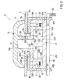
- the outer peripheral ring 40 is formed in a shape of a cylindrical tube having a top plate portion 41. According to the outer peripheral ring 40, the rotating member 20 and the slide member 30 are assembled within the cylindrical tube as the rotating member 20 and the slide member 30 mentioned above are inserted into a cylindrical tubular portion 42 from a lower opening portion 42C. In detail, as shown in Fig.
- the slide member 30 is assembled within the cylindrical tube of the outer peripheral ring 40 by bringing the neck portion 33 into an inserted state into a hole of a through hole 41C formed in the top plate portion 41 and by bringing the upper face 32B of the stepped portion 32 into a face contact state with the inner bottom face 41 A of the top plate portion 41 of the outer peripheral ring 40.
- the outer peripheral ring 40 is assembled into a state where the through hole 41 C fonned in the top plate portion 41 axially aligns with a through hole 5c formed in the shield 5. According to the outer peripheral ring 40, an upper face 41B thereof is arranged away from an inner side face 5b of the shield 5 so as not to contact therewith.
- the outer peripheral ring 40 is attached to the base 60 by fitting two engaging claws 42D, 42D, which are formed to project at portions on a side of a lower edge of the cylindrical portion 42, into engaging holes 61, 61 formed through the base 60 described later and so as to be engaged therewith, respectively.
- the outer peripheral ring 40 is attached to the base 60 in the state that the rotating member 20 and the slide member 30 described above as well as the inner peripheral ring 50 described later are assembled within the cylindrical tube.
- the cylindrical tubular portion 42 of the outer peripheral ring 40 is formed to have a large inner diameter size permitting the barrel portion 31 of the slide member 30 to slide in a diametrical direction within the cylindrical tube.
- the through hole 41C formed in the top plate portion 41 is also formed to have a large diameter size permitting the neck portion 33 to move when the above-described slide member 30 is slid to move. Further, when the slide member 30 is moves to slide, the slide member 30 moves to slide in the diametrical direction while an upper face 32B of the stepped portion 32 slides on the inner bottom face 41 A of the top plate portion 41 of the outer peripheral ring 40.
- the inner peripheral ring 50 is formed in a shape of a cylindrical tube having the bottom plate portion 51.
- the inner peripheral ring 50 is assembled within the cylindrical tube as it is inserted into the cylindrical tubular portion 42 of the outer peripheral ring 40 from the lower opening portion 42C. Therefore, as shown in Fig. 4 , the inner peripheral ring 50 is assembled in such a state that the slide member 30 and the rotating member 20 described above are interposed between the bottom plate portion 51 and the ceiling plate portion 41 of the outer peripheral ring 40.
- slide member 30 can slide to move without rattling in the diametrical direction between the inner peripheral ring 50 and the outer peripheral ring 40.
- compression springs R ⁇ are provided between the cylindrical tubular portion 52 of the inner peripheral ring 50 and the barrel portion 31 of the slide member 30.
- the compression springs R ⁇ are arranged uniformly at four positions in the circumferential direction to be able to urge the barrel portion 31 toward a center position with respect to a radius direction of the cylindrical tubular portion 52. Therefore, when the slide member 30 is slid in any of diametrical directions against the urging of the compression springs R ⁇ , stopping the slide moving operation causes the slide member 30 to return to the center position of the cylindrical tubular portion 52 due to the urging by the compression springs R ⁇ .
- stationary placed contacts 53A through 53E constituted by electrically conductive members are provided on the upper face 51A of the bottom plate portion 51.
- the stationary placed contacts 53A through 53E are disposed at five positions in the circumferential direction, at which the above-described fixed contacts 34A through 34E are disposed
- the stationary placed contacts 53A through 53E always electrically conductively contact with lower end portions of the respective fixed contacts 34A through 34E mentioned above, which extend to lower edge side portions of the barrel portion 31 of the slide member 30 sliding on the upper face 51A of the bottom plate portion 51.
- the stationary placed contacts 53A through 53E are formed to spread in a direction within a plane of the upper face 51A to be able to always contact with the respective fixed contacts 34A through 34E even when the slide member 30 is moved to slide in forward, rearward, upward and downward directions on the upper face 51A of the bottom plate portion 51. Further, although the illustration is omitted, a stationary placed contact similar to the stationary placed contacts 53A through 53E is provided also at a position for contacting with a lower end portion of the common contact 35 extended to a portion on the lower edge side of the barrel portion 31 of the slide member 30.
- the base 60 is formed in a shape of a plate and is integrally assembled with the outer peripheral ring 40 by fitting the engaging claws 42D, 42D of the above-described outer peripheral ring 40 into two engaging holes 61, 61 formed to penetrate the plate in a thickness direction.
- the base 60 is provided with the terminals 63 electrically connected to the slide detecting switches T ⁇ embedded into the cylindrical tubular portion 52 of the inner peripheral ring 50, the fixed contacts 34A through 34E (see Fig. 7 ) embedded into the stepped portion 32, and the common contact 35.
- the position P1 is set to a pivoting position at which an index portion 12 set to the operation member 10 is on the upper side and directed slightly rearwardly to indicate an attitude direction of the seat back 2 normally used. Further, the position P2 is set to a pivoting position substantially at a midpoint between the position P1 and a position P3 described later. Further, the position P3 is set to a pivoting position at which the index portion 12 is directed forwardly to indicate an attitude direction of the seat cushion 3.
- the position P4 is set to a pivoting position at which the index portion 12 is directed to the rear side relative to the position P1, that is, a pivoting position indicating a direction of reclining the seat back 2 rearwardly.
- the position P5 is set to a pivoting position at which the index portion 12 is directed downward relative to the position P3, that is, a pivoting position of indicating a direction of downwardly inclining the attitude direction of the seat cushion 3.
- the operation member 10 is returned to the center position taken before the operation, and the operation of the head rest lifting and lowering device A is stopped. Further, when the operation member 10 is slid to move downwardly of the vehicle seat 1 (see Fig. 2 ), that is, downwardly in the paper face of Fig. 9 (diametrical direction), based on the slide position information, the height position of the head rest 4 is pulled down downwardly same as the operating direction of the operation member 10.
- a position of the support plate Da supporting the waist portion of the seated person is operated to move in the forward, rearward, upward or downward direction same as the operating direction of the operation member 10. Further, by stopping the slide moving operation of the operation member 10, similar to the above-described operation structure, the operation of the lumbar support device D is stopped.
- the operation member 10 when the operation member 10 is slid to move to upwardly or downwardly of the vehicle seat 1 (see Fig. 2 ), based on the slide position information, the lifter device G is electrically operated. Therefore, the height position of the seat cushion 3 (the entire vehicle seat 1) opposed to the vehicular floor face is operated to move in the upward or downward direction same as the operating direction of the operation member 10. Further, by stopping the slide moving operation of the operation member 10, similar to the above-described operation structure, the operation of the slide device H or the lifter device G is stopped
- the seat back middle folding device B is electrically operated. Therefore, the upper body support portion 2A of the seat back 2 supporting the upper body of the back portion of the seated person is moved relative to the lower body support portion 2B to fold in the forward direction or is returned in the rearward direction same as the operating direction of the operation member 10.
- both side portions 2C, 2C in the width direction of the seat back 2 are deformed to move forwardly in such a manner that they move toward each other to the inner side, or return rearwardly. Further, similar to the above-described operation structure, the operation of the seat back middle folding device B or the side support device C is stopped by stopping the slide moving operation of the operation member 10.
- the front portion 3A of the seat cushion 3 is operated to move relative to the rear portion 3B in the forward or rearward direction or upward or downward direction same as the operation direction of the operation member 10. Further, similar to the above-described operation structure, by stopping the slide moving operation of the operation member 10, the operation of the cushion front portion movable device F is stopped.
- the electric function intended to be activated is selected by the operation for pivoting the operating member 10 about the axis.
- setting the index portion 12 to the pivoting position P1 by operating to pivot the operating member 10 about the axis may result in the state of selecting the reclining device E and the head rest lifting and lowering device A as the operational objects.
- the operating member 10 is moved to slide in the forward or rearward direction or the upward or downward direction of the vehicle seat (see Fig. 1 ) for operating to activate the electric functions selected as the operational objects. Therefore, each of the selected electric functions is operated for activation based on the slide position information to which the operating member 10 has been operated to slidably move.
- the height position of the head rest 4 or the back leaning angle position of the seat back 2 are operated to be moved in the same direction as the direction in which the operation member 10 has been operated.
- the electric operating device of the vehicle seat of this embodiment by operating to pivot the operation member 10 about the axis, it is possible to select an operational object from among the plurality of the electric functions. Further, by operating to slide to move the operation member 10 in the diametrical direction directly after that, the electric function selected as the operational object is operated for activation. Therefore, in the case that the number of the electric functions is increased, it can be dealt by increasing the set number of the pivoting positions for selecting the electric functions by the pivoting operation about the axis of the operation member 10.
- the operation can be easily performed without need of groping for the other operation switch. Further, because it is possible to move a component of the vehicle seat 1, such as the seat back 2 and the head rest 4 or the like, in a direction that is the same as the direction in which the operation member 10 has been moved to slide, it is possible to easily imagine the operational direction intended for movement, and the operation can be easily performed.
- the operating member 10 is configured such that a constant click feeling is given against the operational force for pivoting it when it is set to each of the positions P1-P5. Therefore, it is possible to easily position the operating member 10 at a target pivoting position, for example, by pivoting the operating member 10 in the pivoting direction of one side as far as it goes, and by gradually returning the operation for pivoting about the axis.
- the operation member 10 of the electric operating device 6 is formed such that the shape of an entire operating portion that is operated to be grasped is elongated in the diametrical direction. Therefore, a pivoting position of the operation member 10 is indexed by the elongating direction. An end portion of the operation member 10 on the side of indexing the pivoting position is formed such that its shape becomes gradually thicker from the side of the other end.
- FIG. 10 the state where the operating member 10 is set to the position P1 is shown as a solid line state, and the state where it is set to the position P3 is shown as an imaginary line state.
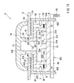
- a central portion having a shape of extending in a diametrical direction is connected to the fitting portion 21 of the rotating member, and the operating member10 is configured to be operated to pivot about this connecting portion.
- the operation member 10 of this embodiment is also formed to have a shape elongated in the diametrical direction.
- a central axis for the operation of pivoting about the axis is set at a position of an end position opposite to an end portion for indexing the pivoting position. Therefore, the indexing direction can be changed with an operation feeling same as tilting up and down the seat back 2 relative to the seat cushion 3.
- Fig. 12 the state of setting the operating member 10 to the position P1 is shown in a solid line state and the state of setting to the position P3 is shown in a imaginary line state, respectively.
- An operation portion 13 of the operation member 10 operated to be grasped of this embodiment is also formed to have a shape elongated in the diametrical direction.
- This operation portion 13 is formed integrally on a disk-like slide plate 14.
- the slide plate 14 is set such that a lozenge through-hole 5c formed in a shield 5 to extend threrethrough is applied from the inner side.
- FIG. 13 the state where the operating member 10 is set to the position P1 is shown as a solid line state, and the state where it is set to the position P3 is shown as an imaginary line state.
- the present invention can be carried out in various kinds of configuration other than the above-described embodiments.
- the functions such as the lumbar support device or the side support device, additionally used for the purpose of improving comfort
- the state of use can be switched to ON/OFF without adjusting the position by the operation of slidably moving the operating member in the diametrical direction.
- an electric function having strongness and weakness in its output such as a vibrator for massage and a heater
- switching of the electric function is set by five steps by the operation of pivoting the operation member about the axis, the number of the steps may be suitably set depending on the number of the electric functions provided at the vehicle seat.
Landscapes
- Engineering & Computer Science (AREA)
- Human Computer Interaction (AREA)
- Aviation & Aerospace Engineering (AREA)
- Transportation (AREA)
- Mechanical Engineering (AREA)
- Seats For Vehicles (AREA)
- Switches With Compound Operations (AREA)
- Lock And Its Accessories (AREA)
Claims (5)
- Fahrzeugsitz (1) mit einer elektrischen Bedienvorrichtung (6), mit:einem am Fahrzeugsitz (1) vorgesehenen Bedienelement (10) zum Aktivieren einer Vielzahl elektrischer Funktion;wobei das außen am Fahrzeugsitz (1) vorgesehene Bedienelement (10) von einer auf dem Fahrzeugsitz (1) sitzenden Person bedienbar ist; dadurch gekennzeichnet, dassdas Bedienelement (10) so ausgebildet ist, dass es um eine Achse drehbar und in eine diametrale Richtung verschiebbar ist, eine Drehbedienstruktur zum Schalten der Drehposition des Bedienelements (10) als eine Funktionsschaltstruktur zum Wählen einer-elektrischen Funktion als ein Bedienobjekt aus einer Vielzahl von elektrischen Funktionen konfiguriert ist, und eine Schiebebedienstruktur zum Schalten der Schiebeposition in der diametralen Richtung des Bedienelements (10) als eine Aktivierungssteuerstruktur zum Aktivieren der als Bedienobjekt gewählten elektrischen Funktion konfiguriert ist.
- Fahrzeugsitz nach Anspruch 1,
wobei das Bedienelement (10) einen Anzeigeabschnitt mit einer in diametraler Richtung langgestreckten Form hat und die Richtung des langgestreckten Anzeigeabschnitts durch eine Berührung desselben fühlbar ist;
wobei die Funktionsschaltstruktur so konfiguriert ist, dass durch eine Drehbedienung des Bedienelements (10) um die Achse eine die Rückenlehne (2) betreffende elektrische Funktion gewählt wird, wenn der Anzeigeabschnitt so ausgerichtet wird, dass er entsprechend der Ausrichtung der Rückenlehne (2) die Aufwärts- oder Abwärtsrichtung des Fahrzeugsitzes (1) anzeigt, und eine das Sitzkissen (3) betreffende elektrische Funktion gewählt wird, wenn der Anzeigeabschnitt so ausgerichtet wird, dass er entsprechend der Ausrichtung des Sitzkissens (3) die Vorwärts- oder Rückwärtsrichtung des Fahrzeugsitzes (1) anzeigt. - Fahrzeugsitz (1) nach Anspruch 2,
wobei der in diametraler Richtung langgestreckte Anzeigeabschnitt als ein durch Ergreifen zu betätigender Bedienabschnitt des Bedienelements (10) eingerichtet ist. - Fahrzeugsitz (1) nach Anspruch 3,
wobei in dem Zustand, in dem der Anzeigeabschnitt so ausgerichtet ist, dass er die Vorwärts-/Rückwärtsrichtung des Fahrzeugs anzeigt, die Mittelachse für die Drehbewegung um die Achse des Bedienelements (10) an einer Stelle hinter der Mitte der in der Vorwärts-/Rückwärtsrichtung langgestreckten Form liegt. - Fahrzeugsitz (1) nach Anspruch 4,
wobei eine der Vielzahl von elektrischen Funktionen als eine Positionseinstellfunktion definiert ist, die durch eine Schiebebedienung des Bedienelements (10) in die diametrale Richtung eine Positionsverstellung einer Komponente des Fahrzeugsitzes (1) in Richtung der Schiebebewegung ermöglicht.
Applications Claiming Priority (2)
| Application Number | Priority Date | Filing Date | Title |
|---|---|---|---|
| JP2006321582A JP4680170B2 (ja) | 2006-11-29 | 2006-11-29 | 車両用シートの電動操作装置 |
| PCT/JP2007/069943 WO2008065815A1 (en) | 2006-11-29 | 2007-10-12 | Electric operating device for vehicle seat |
Publications (3)
| Publication Number | Publication Date |
|---|---|
| EP2088608A1 EP2088608A1 (de) | 2009-08-12 |
| EP2088608A4 EP2088608A4 (de) | 2010-06-02 |
| EP2088608B1 true EP2088608B1 (de) | 2011-06-22 |
Family
ID=39467614
Family Applications (1)
| Application Number | Title | Priority Date | Filing Date |
|---|---|---|---|
| EP07829679A Not-in-force EP2088608B1 (de) | 2006-11-29 | 2007-10-12 | Fahrzeugsitz mit elektrischer bedienvorrichtung |
Country Status (6)
| Country | Link |
|---|---|
| US (1) | US8367949B2 (de) |
| EP (1) | EP2088608B1 (de) |
| JP (1) | JP4680170B2 (de) |
| CN (1) | CN101542665B (de) |
| AT (1) | ATE514173T1 (de) |
| WO (1) | WO2008065815A1 (de) |
Families Citing this family (8)
| Publication number | Priority date | Publication date | Assignee | Title |
|---|---|---|---|---|
| JP5181561B2 (ja) * | 2007-07-20 | 2013-04-10 | トヨタ紡織株式会社 | 車両用シートのシートスイッチ |
| JP2011011606A (ja) * | 2009-07-01 | 2011-01-20 | Nhk Spring Co Ltd | 操作装置 |
| WO2011072389A1 (en) * | 2009-12-17 | 2011-06-23 | Omron Dualtec Automotive Electronics Inc. | Power seat switch assembly |
| KR101144812B1 (ko) * | 2010-05-11 | 2012-05-11 | 엘지전자 주식회사 | 안마의자 및 이에 대한 제어방법 |
| US9446690B2 (en) | 2012-08-31 | 2016-09-20 | Nhk Spring Co., Ltd. | Power seat operation device and power seat |
| JP5838947B2 (ja) * | 2012-10-15 | 2016-01-06 | 住友電装株式会社 | 複合操作装置 |
| JP5838946B2 (ja) * | 2012-10-15 | 2016-01-06 | 住友電装株式会社 | 複合操作装置 |
| GB2535535B (en) * | 2015-02-23 | 2019-05-29 | Jaguar Land Rover Ltd | Seat control apparatus |
Family Cites Families (17)
| Publication number | Priority date | Publication date | Assignee | Title |
|---|---|---|---|---|
| US3483337A (en) * | 1967-01-06 | 1969-12-09 | Gen Motors Corp | Six-way rotary inclined plane centering switch |
| FR2664544B1 (fr) * | 1990-07-12 | 1993-12-17 | Faure Automobile Bertrand | Bloc de commande centralise pour siege de vehicule. |
| JPH0647031A (ja) | 1992-07-31 | 1994-02-22 | Hitachi Medical Corp | 操作卓 |
| JP3340883B2 (ja) * | 1995-03-29 | 2002-11-05 | 株式会社タチエス | 車両用シートの制御装置 |
| JPH0922642A (ja) * | 1995-07-07 | 1997-01-21 | Yazaki Corp | 多方向切換スイッチ |
| JPH09109746A (ja) | 1995-10-24 | 1997-04-28 | Nissan Diesel Motor Co Ltd | 車両のシート装置 |
| JP2001084873A (ja) * | 1999-09-16 | 2001-03-30 | Tokai Rika Co Ltd | スイッチ装置 |
| JP2001202851A (ja) | 2000-01-14 | 2001-07-27 | Alps Electric Co Ltd | ロータリースイッチ |
| DE10124246C1 (de) * | 2001-05-18 | 2002-11-07 | Delphi Tech Inc | Multifunktionsschalter |
| ITTO20020165A1 (it) * | 2002-02-27 | 2003-08-27 | Bitron Spa | Comando manuale per la regolazione della posizione di un sedile. |
| JP2004288393A (ja) | 2003-03-19 | 2004-10-14 | Alps Electric Co Ltd | 車両用パワーシートスイッチ装置 |
| DE10353403B4 (de) | 2003-11-07 | 2014-06-05 | Volkswagen Ag | Verstellschalteranordnung zur Einstellung eines Kraftfahrzeugsitzes, insbesondere Joystickverstellung |
| JP2005313696A (ja) * | 2004-04-27 | 2005-11-10 | Aisin Seiki Co Ltd | シート装置 |
| JP2005317377A (ja) | 2004-04-28 | 2005-11-10 | Calsonic Kansei Corp | 複合操作入力装置 |
| JP2006004091A (ja) | 2004-06-16 | 2006-01-05 | Alps Electric Co Ltd | 力覚付与型入力装置 |
| JP2006088718A (ja) * | 2004-09-21 | 2006-04-06 | Honda Motor Co Ltd | シートの調整装置 |
| JP4446925B2 (ja) * | 2005-04-28 | 2010-04-07 | ホシデン株式会社 | スライド操作式スイッチ |
-
2006
- 2006-11-29 JP JP2006321582A patent/JP4680170B2/ja not_active Expired - Fee Related
-
2007
- 2007-10-12 CN CN2007800438828A patent/CN101542665B/zh not_active Expired - Fee Related
- 2007-10-12 US US12/515,060 patent/US8367949B2/en not_active Expired - Fee Related
- 2007-10-12 WO PCT/JP2007/069943 patent/WO2008065815A1/ja not_active Ceased
- 2007-10-12 EP EP07829679A patent/EP2088608B1/de not_active Not-in-force
- 2007-10-12 AT AT07829679T patent/ATE514173T1/de not_active IP Right Cessation
Also Published As
| Publication number | Publication date |
|---|---|
| WO2008065815A1 (en) | 2008-06-05 |
| US20100044202A1 (en) | 2010-02-25 |
| US8367949B2 (en) | 2013-02-05 |
| CN101542665A (zh) | 2009-09-23 |
| ATE514173T1 (de) | 2011-07-15 |
| CN101542665B (zh) | 2011-09-14 |
| JP4680170B2 (ja) | 2011-05-11 |
| EP2088608A1 (de) | 2009-08-12 |
| JP2008135323A (ja) | 2008-06-12 |
| EP2088608A4 (de) | 2010-06-02 |
Similar Documents
| Publication | Publication Date | Title |
|---|---|---|
| EP2095991B1 (de) | Vorrichtung zur elektrischen betätigung für einen fahrzeugsitz | |
| EP2088608B1 (de) | Fahrzeugsitz mit elektrischer bedienvorrichtung | |
| EP1942029B1 (de) | Sitz | |
| EP2216201B1 (de) | Elektrische Sitzsteuerungseinheit | |
| EP1111637A2 (de) | Mehrfachschalter | |
| EP2991091B1 (de) | Multidirektionaler betriebsschalter | |
| US11584260B2 (en) | Power seat operating device having seesaw type switch for vehicle | |
| US20080245650A1 (en) | Operating element with a central pushbutton | |
| US20080143160A1 (en) | Device for Limiting the Adjustability of a Vehicle Seat | |
| EP3859762B1 (de) | Freigabeschalter | |
| US6262379B1 (en) | Switch apparatus | |
| JP4800183B2 (ja) | 車両用シートの電動操作装置 | |
| US11623546B2 (en) | Seat switch device | |
| JP4869886B2 (ja) | 車両用シートの電動操作装置 | |
| EP2458608B1 (de) | Elektrischer Schalter | |
| JP2006088718A (ja) | シートの調整装置 | |
| US20090184938A1 (en) | Touch Screen Switching Assembly | |
| JP5386188B2 (ja) | パワーシートの調整装置 | |
| JP5181561B2 (ja) | 車両用シートのシートスイッチ | |
| JP2009158351A (ja) | シートスイッチ装置およびこのシートスイッチ装置に対して電気的に接続された制御装置 | |
| JPH0647031U (ja) | 座席用パワーシートスイッチ | |
| JP2009170144A (ja) | シートスイッチ装置およびこのシートスイッチ装置に対して電気的に接続された制御装置 | |
| JP2009208550A (ja) | 車両用シート | |
| JP2009161097A (ja) | 車両用シート |
Legal Events
| Date | Code | Title | Description |
|---|---|---|---|
| PUAI | Public reference made under article 153(3) epc to a published international application that has entered the european phase |
Free format text: ORIGINAL CODE: 0009012 |
|
| 17P | Request for examination filed |
Effective date: 20090526 |
|
| AK | Designated contracting states |
Kind code of ref document: A1 Designated state(s): AT BE BG CH CY CZ DE DK EE ES FI FR GB GR HU IE IS IT LI LT LU LV MC MT NL PL PT RO SE SI SK TR |
|
| DAX | Request for extension of the european patent (deleted) | ||
| A4 | Supplementary search report drawn up and despatched |
Effective date: 20100503 |
|
| GRAP | Despatch of communication of intention to grant a patent |
Free format text: ORIGINAL CODE: EPIDOSNIGR1 |
|
| RIC1 | Information provided on ipc code assigned before grant |
Ipc: B60N 2/44 20060101ALI20101126BHEP Ipc: H01H 25/00 20060101AFI20101126BHEP Ipc: H01H 25/06 20060101ALI20101126BHEP |
|
| GRAS | Grant fee paid |
Free format text: ORIGINAL CODE: EPIDOSNIGR3 |
|
| GRAA | (expected) grant |
Free format text: ORIGINAL CODE: 0009210 |
|
| AK | Designated contracting states |
Kind code of ref document: B1 Designated state(s): AT BE BG CH CY CZ DE DK EE ES FI FR GB GR HU IE IS IT LI LT LU LV MC MT NL PL PT RO SE SI SK TR |
|
| REG | Reference to a national code |
Ref country code: GB Ref legal event code: FG4D |
|
| REG | Reference to a national code |
Ref country code: CH Ref legal event code: EP |
|
| REG | Reference to a national code |
Ref country code: IE Ref legal event code: FG4D |
|
| REG | Reference to a national code |
Ref country code: DE Ref legal event code: R096 Ref document number: 602007015425 Country of ref document: DE Effective date: 20110811 |
|
| REG | Reference to a national code |
Ref country code: NL Ref legal event code: VDEP Effective date: 20110622 |
|
| PG25 | Lapsed in a contracting state [announced via postgrant information from national office to epo] |
Ref country code: SE Free format text: LAPSE BECAUSE OF FAILURE TO SUBMIT A TRANSLATION OF THE DESCRIPTION OR TO PAY THE FEE WITHIN THE PRESCRIBED TIME-LIMIT Effective date: 20110622 Ref country code: LT Free format text: LAPSE BECAUSE OF FAILURE TO SUBMIT A TRANSLATION OF THE DESCRIPTION OR TO PAY THE FEE WITHIN THE PRESCRIBED TIME-LIMIT Effective date: 20110622 |
|
| PG25 | Lapsed in a contracting state [announced via postgrant information from national office to epo] |
Ref country code: AT Free format text: LAPSE BECAUSE OF FAILURE TO SUBMIT A TRANSLATION OF THE DESCRIPTION OR TO PAY THE FEE WITHIN THE PRESCRIBED TIME-LIMIT Effective date: 20110622 Ref country code: SI Free format text: LAPSE BECAUSE OF FAILURE TO SUBMIT A TRANSLATION OF THE DESCRIPTION OR TO PAY THE FEE WITHIN THE PRESCRIBED TIME-LIMIT Effective date: 20110622 Ref country code: GR Free format text: LAPSE BECAUSE OF FAILURE TO SUBMIT A TRANSLATION OF THE DESCRIPTION OR TO PAY THE FEE WITHIN THE PRESCRIBED TIME-LIMIT Effective date: 20110923 Ref country code: FI Free format text: LAPSE BECAUSE OF FAILURE TO SUBMIT A TRANSLATION OF THE DESCRIPTION OR TO PAY THE FEE WITHIN THE PRESCRIBED TIME-LIMIT Effective date: 20110622 Ref country code: LV Free format text: LAPSE BECAUSE OF FAILURE TO SUBMIT A TRANSLATION OF THE DESCRIPTION OR TO PAY THE FEE WITHIN THE PRESCRIBED TIME-LIMIT Effective date: 20110622 Ref country code: CY Free format text: LAPSE BECAUSE OF FAILURE TO SUBMIT A TRANSLATION OF THE DESCRIPTION OR TO PAY THE FEE WITHIN THE PRESCRIBED TIME-LIMIT Effective date: 20110622 |
|
| PG25 | Lapsed in a contracting state [announced via postgrant information from national office to epo] |
Ref country code: NL Free format text: LAPSE BECAUSE OF FAILURE TO SUBMIT A TRANSLATION OF THE DESCRIPTION OR TO PAY THE FEE WITHIN THE PRESCRIBED TIME-LIMIT Effective date: 20110622 Ref country code: BE Free format text: LAPSE BECAUSE OF FAILURE TO SUBMIT A TRANSLATION OF THE DESCRIPTION OR TO PAY THE FEE WITHIN THE PRESCRIBED TIME-LIMIT Effective date: 20110622 |
|
| PG25 | Lapsed in a contracting state [announced via postgrant information from national office to epo] |
Ref country code: EE Free format text: LAPSE BECAUSE OF FAILURE TO SUBMIT A TRANSLATION OF THE DESCRIPTION OR TO PAY THE FEE WITHIN THE PRESCRIBED TIME-LIMIT Effective date: 20110622 Ref country code: IS Free format text: LAPSE BECAUSE OF FAILURE TO SUBMIT A TRANSLATION OF THE DESCRIPTION OR TO PAY THE FEE WITHIN THE PRESCRIBED TIME-LIMIT Effective date: 20111022 Ref country code: CZ Free format text: LAPSE BECAUSE OF FAILURE TO SUBMIT A TRANSLATION OF THE DESCRIPTION OR TO PAY THE FEE WITHIN THE PRESCRIBED TIME-LIMIT Effective date: 20110622 Ref country code: PT Free format text: LAPSE BECAUSE OF FAILURE TO SUBMIT A TRANSLATION OF THE DESCRIPTION OR TO PAY THE FEE WITHIN THE PRESCRIBED TIME-LIMIT Effective date: 20111024 |
|
| PG25 | Lapsed in a contracting state [announced via postgrant information from national office to epo] |
Ref country code: PL Free format text: LAPSE BECAUSE OF FAILURE TO SUBMIT A TRANSLATION OF THE DESCRIPTION OR TO PAY THE FEE WITHIN THE PRESCRIBED TIME-LIMIT Effective date: 20110622 Ref country code: RO Free format text: LAPSE BECAUSE OF FAILURE TO SUBMIT A TRANSLATION OF THE DESCRIPTION OR TO PAY THE FEE WITHIN THE PRESCRIBED TIME-LIMIT Effective date: 20110622 Ref country code: SK Free format text: LAPSE BECAUSE OF FAILURE TO SUBMIT A TRANSLATION OF THE DESCRIPTION OR TO PAY THE FEE WITHIN THE PRESCRIBED TIME-LIMIT Effective date: 20110622 |
|
| PLBE | No opposition filed within time limit |
Free format text: ORIGINAL CODE: 0009261 |
|
| STAA | Information on the status of an ep patent application or granted ep patent |
Free format text: STATUS: NO OPPOSITION FILED WITHIN TIME LIMIT |
|
| 26N | No opposition filed |
Effective date: 20120323 |
|
| PG25 | Lapsed in a contracting state [announced via postgrant information from national office to epo] |
Ref country code: MC Free format text: LAPSE BECAUSE OF NON-PAYMENT OF DUE FEES Effective date: 20111031 Ref country code: IT Free format text: LAPSE BECAUSE OF FAILURE TO SUBMIT A TRANSLATION OF THE DESCRIPTION OR TO PAY THE FEE WITHIN THE PRESCRIBED TIME-LIMIT Effective date: 20110622 |
|
| REG | Reference to a national code |
Ref country code: CH Ref legal event code: PL |
|
| GBPC | Gb: european patent ceased through non-payment of renewal fee |
Effective date: 20111012 |
|
| PG25 | Lapsed in a contracting state [announced via postgrant information from national office to epo] |
Ref country code: DK Free format text: LAPSE BECAUSE OF FAILURE TO SUBMIT A TRANSLATION OF THE DESCRIPTION OR TO PAY THE FEE WITHIN THE PRESCRIBED TIME-LIMIT Effective date: 20110622 |
|
| REG | Reference to a national code |
Ref country code: DE Ref legal event code: R097 Ref document number: 602007015425 Country of ref document: DE Effective date: 20120323 |
|
| REG | Reference to a national code |
Ref country code: FR Ref legal event code: ST Effective date: 20120629 |
|
| PG25 | Lapsed in a contracting state [announced via postgrant information from national office to epo] |
Ref country code: CH Free format text: LAPSE BECAUSE OF NON-PAYMENT OF DUE FEES Effective date: 20111031 Ref country code: LI Free format text: LAPSE BECAUSE OF NON-PAYMENT OF DUE FEES Effective date: 20111031 |
|
| REG | Reference to a national code |
Ref country code: IE Ref legal event code: MM4A |
|
| PG25 | Lapsed in a contracting state [announced via postgrant information from national office to epo] |
Ref country code: GB Free format text: LAPSE BECAUSE OF NON-PAYMENT OF DUE FEES Effective date: 20111012 Ref country code: FR Free format text: LAPSE BECAUSE OF NON-PAYMENT OF DUE FEES Effective date: 20111102 |
|
| PG25 | Lapsed in a contracting state [announced via postgrant information from national office to epo] |
Ref country code: IE Free format text: LAPSE BECAUSE OF NON-PAYMENT OF DUE FEES Effective date: 20111012 |
|
| PG25 | Lapsed in a contracting state [announced via postgrant information from national office to epo] |
Ref country code: MT Free format text: LAPSE BECAUSE OF FAILURE TO SUBMIT A TRANSLATION OF THE DESCRIPTION OR TO PAY THE FEE WITHIN THE PRESCRIBED TIME-LIMIT Effective date: 20110622 |
|
| PG25 | Lapsed in a contracting state [announced via postgrant information from national office to epo] |
Ref country code: ES Free format text: LAPSE BECAUSE OF FAILURE TO SUBMIT A TRANSLATION OF THE DESCRIPTION OR TO PAY THE FEE WITHIN THE PRESCRIBED TIME-LIMIT Effective date: 20111003 |
|
| PG25 | Lapsed in a contracting state [announced via postgrant information from national office to epo] |
Ref country code: LU Free format text: LAPSE BECAUSE OF NON-PAYMENT OF DUE FEES Effective date: 20111012 |
|
| PG25 | Lapsed in a contracting state [announced via postgrant information from national office to epo] |
Ref country code: BG Free format text: LAPSE BECAUSE OF FAILURE TO SUBMIT A TRANSLATION OF THE DESCRIPTION OR TO PAY THE FEE WITHIN THE PRESCRIBED TIME-LIMIT Effective date: 20110922 |
|
| PG25 | Lapsed in a contracting state [announced via postgrant information from national office to epo] |
Ref country code: TR Free format text: LAPSE BECAUSE OF FAILURE TO SUBMIT A TRANSLATION OF THE DESCRIPTION OR TO PAY THE FEE WITHIN THE PRESCRIBED TIME-LIMIT Effective date: 20110622 |
|
| PG25 | Lapsed in a contracting state [announced via postgrant information from national office to epo] |
Ref country code: HU Free format text: LAPSE BECAUSE OF FAILURE TO SUBMIT A TRANSLATION OF THE DESCRIPTION OR TO PAY THE FEE WITHIN THE PRESCRIBED TIME-LIMIT Effective date: 20110622 |
|
| PGFP | Annual fee paid to national office [announced via postgrant information from national office to epo] |
Ref country code: DE Payment date: 20131009 Year of fee payment: 7 |
|
| REG | Reference to a national code |
Ref country code: DE Ref legal event code: R119 Ref document number: 602007015425 Country of ref document: DE |
|
| PG25 | Lapsed in a contracting state [announced via postgrant information from national office to epo] |
Ref country code: DE Free format text: LAPSE BECAUSE OF NON-PAYMENT OF DUE FEES Effective date: 20150501 |