EP2088649A1 - Einrichtung und verfahren zum krimpen eines elektrischen drahtanschlusses - Google Patents
Einrichtung und verfahren zum krimpen eines elektrischen drahtanschlusses Download PDFInfo
- Publication number
- EP2088649A1 EP2088649A1 EP07831755A EP07831755A EP2088649A1 EP 2088649 A1 EP2088649 A1 EP 2088649A1 EP 07831755 A EP07831755 A EP 07831755A EP 07831755 A EP07831755 A EP 07831755A EP 2088649 A1 EP2088649 A1 EP 2088649A1
- Authority
- EP
- European Patent Office
- Prior art keywords
- electric wire
- terminal
- crimping
- conveying
- hand
- Prior art date
- Legal status (The legal status is an assumption and is not a legal conclusion. Google has not performed a legal analysis and makes no representation as to the accuracy of the status listed.)
- Granted
Links
Images







Classifications
-
- H—ELECTRICITY
- H01—ELECTRIC ELEMENTS
- H01R—ELECTRICALLY-CONDUCTIVE CONNECTIONS; STRUCTURAL ASSOCIATIONS OF A PLURALITY OF MUTUALLY-INSULATED ELECTRICAL CONNECTING ELEMENTS; COUPLING DEVICES; CURRENT COLLECTORS
- H01R43/00—Apparatus or processes specially adapted for manufacturing, assembling, maintaining, or repairing of line connectors or current collectors or for joining electric conductors
- H01R43/04—Apparatus or processes specially adapted for manufacturing, assembling, maintaining, or repairing of line connectors or current collectors or for joining electric conductors for forming connections by deformation, e.g. crimping tool
- H01R43/048—Crimping apparatus or processes
-
- H—ELECTRICITY
- H01—ELECTRIC ELEMENTS
- H01R—ELECTRICALLY-CONDUCTIVE CONNECTIONS; STRUCTURAL ASSOCIATIONS OF A PLURALITY OF MUTUALLY-INSULATED ELECTRICAL CONNECTING ELEMENTS; COUPLING DEVICES; CURRENT COLLECTORS
- H01R43/00—Apparatus or processes specially adapted for manufacturing, assembling, maintaining, or repairing of line connectors or current collectors or for joining electric conductors
- H01R43/04—Apparatus or processes specially adapted for manufacturing, assembling, maintaining, or repairing of line connectors or current collectors or for joining electric conductors for forming connections by deformation, e.g. crimping tool
- H01R43/048—Crimping apparatus or processes
- H01R43/052—Crimping apparatus or processes with wire-feeding mechanism
-
- H—ELECTRICITY
- H01—ELECTRIC ELEMENTS
- H01R—ELECTRICALLY-CONDUCTIVE CONNECTIONS; STRUCTURAL ASSOCIATIONS OF A PLURALITY OF MUTUALLY-INSULATED ELECTRICAL CONNECTING ELEMENTS; COUPLING DEVICES; CURRENT COLLECTORS
- H01R43/00—Apparatus or processes specially adapted for manufacturing, assembling, maintaining, or repairing of line connectors or current collectors or for joining electric conductors
- H01R43/28—Apparatus or processes specially adapted for manufacturing, assembling, maintaining, or repairing of line connectors or current collectors or for joining electric conductors for wire processing before connecting to contact members, not provided for in groups H01R43/02 - H01R43/26
-
- Y—GENERAL TAGGING OF NEW TECHNOLOGICAL DEVELOPMENTS; GENERAL TAGGING OF CROSS-SECTIONAL TECHNOLOGIES SPANNING OVER SEVERAL SECTIONS OF THE IPC; TECHNICAL SUBJECTS COVERED BY FORMER USPC CROSS-REFERENCE ART COLLECTIONS [XRACs] AND DIGESTS
- Y10—TECHNICAL SUBJECTS COVERED BY FORMER USPC
- Y10T—TECHNICAL SUBJECTS COVERED BY FORMER US CLASSIFICATION
- Y10T29/00—Metal working
- Y10T29/49—Method of mechanical manufacture
- Y10T29/49002—Electrical device making
- Y10T29/49117—Conductor or circuit manufacturing
- Y10T29/49174—Assembling terminal to elongated conductor
-
- Y—GENERAL TAGGING OF NEW TECHNOLOGICAL DEVELOPMENTS; GENERAL TAGGING OF CROSS-SECTIONAL TECHNOLOGIES SPANNING OVER SEVERAL SECTIONS OF THE IPC; TECHNICAL SUBJECTS COVERED BY FORMER USPC CROSS-REFERENCE ART COLLECTIONS [XRACs] AND DIGESTS
- Y10—TECHNICAL SUBJECTS COVERED BY FORMER USPC
- Y10T—TECHNICAL SUBJECTS COVERED BY FORMER US CLASSIFICATION
- Y10T29/00—Metal working
- Y10T29/49—Method of mechanical manufacture
- Y10T29/49002—Electrical device making
- Y10T29/49117—Conductor or circuit manufacturing
- Y10T29/49174—Assembling terminal to elongated conductor
- Y10T29/49181—Assembling terminal to elongated conductor by deforming
-
- Y—GENERAL TAGGING OF NEW TECHNOLOGICAL DEVELOPMENTS; GENERAL TAGGING OF CROSS-SECTIONAL TECHNOLOGIES SPANNING OVER SEVERAL SECTIONS OF THE IPC; TECHNICAL SUBJECTS COVERED BY FORMER USPC CROSS-REFERENCE ART COLLECTIONS [XRACs] AND DIGESTS
- Y10—TECHNICAL SUBJECTS COVERED BY FORMER USPC
- Y10T—TECHNICAL SUBJECTS COVERED BY FORMER US CLASSIFICATION
- Y10T29/00—Metal working
- Y10T29/49—Method of mechanical manufacture
- Y10T29/49002—Electrical device making
- Y10T29/49117—Conductor or circuit manufacturing
- Y10T29/49174—Assembling terminal to elongated conductor
- Y10T29/49181—Assembling terminal to elongated conductor by deforming
- Y10T29/49185—Assembling terminal to elongated conductor by deforming of terminal
-
- Y—GENERAL TAGGING OF NEW TECHNOLOGICAL DEVELOPMENTS; GENERAL TAGGING OF CROSS-SECTIONAL TECHNOLOGIES SPANNING OVER SEVERAL SECTIONS OF THE IPC; TECHNICAL SUBJECTS COVERED BY FORMER USPC CROSS-REFERENCE ART COLLECTIONS [XRACs] AND DIGESTS
- Y10—TECHNICAL SUBJECTS COVERED BY FORMER USPC
- Y10T—TECHNICAL SUBJECTS COVERED BY FORMER US CLASSIFICATION
- Y10T29/00—Metal working
- Y10T29/49—Method of mechanical manufacture
- Y10T29/49002—Electrical device making
- Y10T29/49117—Conductor or circuit manufacturing
- Y10T29/49174—Assembling terminal to elongated conductor
- Y10T29/49181—Assembling terminal to elongated conductor by deforming
- Y10T29/49185—Assembling terminal to elongated conductor by deforming of terminal
- Y10T29/49192—Assembling terminal to elongated conductor by deforming of terminal with insulation removal
-
- Y—GENERAL TAGGING OF NEW TECHNOLOGICAL DEVELOPMENTS; GENERAL TAGGING OF CROSS-SECTIONAL TECHNOLOGIES SPANNING OVER SEVERAL SECTIONS OF THE IPC; TECHNICAL SUBJECTS COVERED BY FORMER USPC CROSS-REFERENCE ART COLLECTIONS [XRACs] AND DIGESTS
- Y10—TECHNICAL SUBJECTS COVERED BY FORMER USPC
- Y10T—TECHNICAL SUBJECTS COVERED BY FORMER US CLASSIFICATION
- Y10T29/00—Metal working
- Y10T29/51—Plural diverse manufacturing apparatus including means for metal shaping or assembling
- Y10T29/5187—Wire working
-
- Y—GENERAL TAGGING OF NEW TECHNOLOGICAL DEVELOPMENTS; GENERAL TAGGING OF CROSS-SECTIONAL TECHNOLOGIES SPANNING OVER SEVERAL SECTIONS OF THE IPC; TECHNICAL SUBJECTS COVERED BY FORMER USPC CROSS-REFERENCE ART COLLECTIONS [XRACs] AND DIGESTS
- Y10—TECHNICAL SUBJECTS COVERED BY FORMER USPC
- Y10T—TECHNICAL SUBJECTS COVERED BY FORMER US CLASSIFICATION
- Y10T29/00—Metal working
- Y10T29/51—Plural diverse manufacturing apparatus including means for metal shaping or assembling
- Y10T29/5193—Electrical connector or terminal
-
- Y—GENERAL TAGGING OF NEW TECHNOLOGICAL DEVELOPMENTS; GENERAL TAGGING OF CROSS-SECTIONAL TECHNOLOGIES SPANNING OVER SEVERAL SECTIONS OF THE IPC; TECHNICAL SUBJECTS COVERED BY FORMER USPC CROSS-REFERENCE ART COLLECTIONS [XRACs] AND DIGESTS
- Y10—TECHNICAL SUBJECTS COVERED BY FORMER USPC
- Y10T—TECHNICAL SUBJECTS COVERED BY FORMER US CLASSIFICATION
- Y10T29/00—Metal working
- Y10T29/53—Means to assemble or disassemble
- Y10T29/5313—Means to assemble electrical device
- Y10T29/532—Conductor
- Y10T29/53209—Terminal or connector
- Y10T29/53213—Assembled to wire-type conductor
-
- Y—GENERAL TAGGING OF NEW TECHNOLOGICAL DEVELOPMENTS; GENERAL TAGGING OF CROSS-SECTIONAL TECHNOLOGIES SPANNING OVER SEVERAL SECTIONS OF THE IPC; TECHNICAL SUBJECTS COVERED BY FORMER USPC CROSS-REFERENCE ART COLLECTIONS [XRACs] AND DIGESTS
- Y10—TECHNICAL SUBJECTS COVERED BY FORMER USPC
- Y10T—TECHNICAL SUBJECTS COVERED BY FORMER US CLASSIFICATION
- Y10T29/00—Metal working
- Y10T29/53—Means to assemble or disassemble
- Y10T29/5313—Means to assemble electrical device
- Y10T29/532—Conductor
- Y10T29/53209—Terminal or connector
- Y10T29/53213—Assembled to wire-type conductor
- Y10T29/53235—Means to fasten by deformation
-
- Y—GENERAL TAGGING OF NEW TECHNOLOGICAL DEVELOPMENTS; GENERAL TAGGING OF CROSS-SECTIONAL TECHNOLOGIES SPANNING OVER SEVERAL SECTIONS OF THE IPC; TECHNICAL SUBJECTS COVERED BY FORMER USPC CROSS-REFERENCE ART COLLECTIONS [XRACs] AND DIGESTS
- Y10—TECHNICAL SUBJECTS COVERED BY FORMER USPC
- Y10T—TECHNICAL SUBJECTS COVERED BY FORMER US CLASSIFICATION
- Y10T29/00—Metal working
- Y10T29/53—Means to assemble or disassemble
- Y10T29/5313—Means to assemble electrical device
- Y10T29/53265—Means to assemble electrical device with work-holder for assembly
-
- Y—GENERAL TAGGING OF NEW TECHNOLOGICAL DEVELOPMENTS; GENERAL TAGGING OF CROSS-SECTIONAL TECHNOLOGIES SPANNING OVER SEVERAL SECTIONS OF THE IPC; TECHNICAL SUBJECTS COVERED BY FORMER USPC CROSS-REFERENCE ART COLLECTIONS [XRACs] AND DIGESTS
- Y10—TECHNICAL SUBJECTS COVERED BY FORMER USPC
- Y10T—TECHNICAL SUBJECTS COVERED BY FORMER US CLASSIFICATION
- Y10T29/00—Metal working
- Y10T29/53—Means to assemble or disassemble
- Y10T29/5313—Means to assemble electrical device
- Y10T29/5327—Means to fasten by deforming
Definitions
- the present invention relates to a device for crimping a terminal of an electric wire and a method for crimping a terminal of an electric wire used for manufacturing wire harness used in vehicles such as automobiles.
- devices for manufacturing wire harness used in vehicles such as automobiles are comprised of: a means for cutting long electric wire in a predetermined length; a means for stripping jacket on both ends of the electric wire; a means for crimping the end of the electric wire to a terminal; and a means for inserting the terminal crimped to the electric wire in a connector housing.
- a means for cutting long electric wire in a predetermined length e.g., a means for stripping jacket on both ends of the electric wire
- a means for crimping the end of the electric wire to a terminal e.g., refer to Patent Documents 1-3).
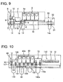
- such prior art wire harness manufacturing device is comprised of an electric wire terminal crimping device as shown in Fig. 10 .
- the electric wire terminal crimping device is comprised of: an electric wire measuring section 80 for measuring the electric wire; a stripping section 100 for stripping jacket on both ends of the electric wire; a terminal crimping section 60 for crimping the terminals at the ends of the electric wire; a terminal-position regulating section 70 for regulating the posture of the terminal; and a terminal-inserting section 110 for inserting the terminal attached wire in a connector housing.
- the electric wire 140 is fed a predetermined amount at the electric wire measuring section 80 and the electric wire 140 is sent into a U-turn mechanism (not illustrated), and thereby, terminal at the downstream end of the electric wire 140 is made to do a U-turn and then held with the electric wire holding hand 101. Thereafter, the electric wire 140 is measured and is driven at the electric wire measurement section 80, and after the measurement ends, the electric wire 140 is cut by a cutter 90 and its terminal at the upstream end is held with the electric wire holding hand 101. At this point, both ends of the electric wire 140 which underwent measurement and cutting are held with the electric wire holding hand 101 and the wire forms a U-shape. The wire is then conveyed to respective process sections by means of an electric wire conveying method which will be described later.
- Jackets on both ends of the U-shaped electric wire 140 are stripped off at the stripping section 100 and the terminals are then crimped to the ends at the terminal crimping section 60.
- a plurality of pressing device 60a is provided in the terminal crimping section 60 so as to enable the crimping of a plurality of types of terminals that configure the wire harness.
- the electric wire holding hand 101 crimps the terminals by advancing the tip of the electric wire 140 inside the pressing device 60a by means of the distance adjusting mechanism 160 that adjusts the strokes of the air cylinder 150 as shown in Figs. 11(A) and (B).
- Fig. 11(A) shows a situation before advancing the tip of the electric wire 140 whereas Fig. 11(B) shows a situation after advancing the tip.
- Position of the terminal-attached electric wire 140a having the terminals which have been crimped is fixed in up-down and left-right directions by the terminal-position regulating section 70 and transferred to the terminal-inserting hand 110a.
- the terminal-inserting hand 110a is a robot having the X-Y-Z axes and it inserts the terminals of the terminal-attached electric wire 140a in the connector housing 130 which is placed in the connector receiving jig 120 positioned in the terminal-inserting section 110.
- the electric wire 140 held with the electric wire holding hand 101 is held with the electric wire conveying hand 103 placed on the electric wire conveying hand unit 102 provided in a parallel direction to each process section described above such as the electric wire measurement section 80, and the electric wire holding hand 101 releases the electric wire 140. Then, after an actuator 50 (e.g., air cylinder) moved the electric wire for a distance corresponding to the installed pitch of the process sections, the electric wire holding hand 101 grips the electric wire 140 once again. Then, the electric wire conveying hand 103 releases the electric wire 140 and the actuator 50 returns to its original position.
- the pitch conveyance of the electric wire 140 is carried out by means of the operation of grip-substituting the electric wire and the intermittent operation of the actuator 50.
- a plurality of pressing device 60a is provided for crimping the terminals, and grip-substituting of the electric wire is done every time for each move for a positioning spacing (one pitch) between the pressing devices 60a. Therefore, as the number of the pressing devices 60a increases or the speed at which the electric wire is conveyed becomes faster, the possibility of holding failure of the electric wire increases in the terminal crimping process performed by the plurality of pressing device 60a. This may lead to products defective in terminal crimping.
- the present invention was invented by focusing attention on such problems involved in prior art, and it is an object of the present invention to provide an electric wire terminal crimping device and an method for crimping an electric wire terminal wherein products defective in terminal crimping due to holding failure of the electric wire is avoided.
- an electric wire terminal crimping device is comprised of: an electric wire crimping means for crimping a terminal at an end of an electric wire; and an electric wire conveying means for holding and conveying an end of said electric wire; and wherein a plurality of said electric wire crimping means is positioned in a row in a direction in which said electric wire is conveyed, said electric wire conveying means conveys said electric wire from one side of said plurality of electric wire crimping means to another side without said electric wire being grip-substituted, and conveyance of said electric wire is capable of being stopped at a discretional one of said plurality of electric wire crimping means.
- the electric wire conveying means conveys the electric wire from one side of the plurality of electric wire crimping means to another side without the electric wire being grip-substituted, even if the number of the electric wire crimping means increased or the conveying speed of the electric wire became faster, holding failure is suppressed and it is able to prevent defective products in terminal crimping due to the holding failure.
- the electric wire terminal crimping device is comprised of: an electric wire measurement means for measuring the electric wire and cutting it in a predetermined length; and a stripping means for stripping jacket on both ends of the electric wire; and wherein said electric wire conveying means includes: a first electric wire conveying hand for conveying said electric wire from said electric wire measurement means to said stripping means; a first driving means for reciprocating said first electric wire conveying hand between said electric wire measurement means and said stripping means; a second electric wire conveying hand for conveying said electric wire from one side of said plurality of electric wire crimping means to another side; and a second driving means for reciprocating said second electric wire conveying hand between one side of said plurality of electric wire crimping means and another side.
- the first electric wire conveying hand takes charge of conveying the electric wire from the electric wire measurement means to the stripping means and the second electric wire conveying hand takes charge of conveying the electric wire from one side of the plurality of electric wire crimping means to another side, there is no change in the posture of the terminal after crimping the terminal.
- two electric wire holding hands for holding both ends of said electric wire are respectively provided in said first electric wire conveying hand and said second electric wire conveying hand.
- the structure can be simplified and faults in the mechanisms can be reduced due to this simple structure.
- third driving means for moving the electric wire holding hands in a direction perpendicular to a conveying direction of said electric wire to a crimp working location of said electric wire crimping means is respectively provided in said two electric wire holding hands provided in said second electric wire conveying hand.
- the moving distance of the electric wire crimping means to the crimp working location can be suitably set with the third driving means that are respectively provided in the two electric wire holding hands of the second electric wire conveying hand, and thereby, changing the moving distance to the crimp working location is easier in case of change in the terminal.
- the electric wire terminal crimping device comprises a grip-substituting hand allocated between said stripping means and said plurality of electric wire crimping means, for receiving the electric wire whose jacket is stripped off from said first electric wire conveying hand and for passing it on to said second electric wire conveying hand.
- a grip-substituting hand allocated between said stripping means and said plurality of electric wire crimping means, for receiving the electric wire whose jacket is stripped off from said first electric wire conveying hand and for passing it on to said second electric wire conveying hand.
- the electric wire terminal crimping device comprises an electric wire protecting cover for covering outer side of said electric wire for entire area in which said electric wire moves from first to last electric wire crimping means among said plurality of electric wire crimping means.
- swinging of the electric wire that occurs when the electric wire is conveyed at high speed from the first electric wire crimping means to the last electric wire crimping means can be prevented by the electric wire protecting cover.
- said electric wire conveying means includes a single electric wire conveying hand for conveying said electric wire from one of said plurality of electric wire crimping means for a prior process to one of said plurality of electric wire crimping means for a later process.
- the structure can be simplified further.
- the electric wire terminal crimping device comprises an electric wire anti-swinging unit allocated in outer side of said electric wire in which its both ends are held with said two electric wire holding hands of said second electric wire conveying hand so that said electric wire is loop-shaped, for regulating position(s) of both sides or one side of said loop-shaped electric wire at position(s) apart from location where said both ends of said electric wire are held with said two electric wire holding hands; and an anti-swinging unit driving means for moving said electric wire anti-swinging unit between a first position located in a motion trajectory of said electric wire upon said electric wire is conveyed between one side of said plurality of electric wire crimping means to another side and a second position retracted from the motion trajectory.
- the electric wire terminal crimping device comprises a cover for protecting internal structure of said second electric wire conveying hand, said electric wire anti-swinging unit, and said anti-swinging unit driving means, and wherein said electric wire anti-swinging unit is configured such that it protrudes from inner side to outer side of said cover to regulate position(s) on both sides or one side of the loop-shaped electric wire at said first position.
- the internal structure of the second electric wire conveying hand, the electric wire anti-swinging unit, and the anti-swinging unit driving means can be protected with the cover.
- the electric wire terminal crimping device comprises an electric wire guiding member allocated such that there is spacing between itself and the cover on the cover, and wherein upon the electric wire is conveyed between one side of said plurality of electric wire crimping means to another side, said electric wire passes through the spacing between the cover and the electric wire guiding member.
- the electric wire passes through the spacing between the cover and the electric wire guiding member, and by making this spacing narrow to enable the electric wire to pass through it, the electric wire can be prevented from being swung above the cover by stopping it with the electric wire guiding member.
- the electric wire guiding member prevents the electric wire from crossing over the electric wire anti-swinging unit.
- said electric wire anti-swinging unit is a guide rod capable of contacting outer side of the electric wire at both sides or one side of the loop-shaped electric wire when said electric wire anti-swinging unit is in said first position.
- the guide rod upon the above move, when position on one side or both sides of the electric wire is regulated by the guide rod, the fulcrum point at which the loop-shaped electric wire bends is in the vicinity of the guide rod that is placed apart from the position at which both the electric wire terminals are held with the two electric wire holding hands.
- the guide rod can control the electric wire from swinging in a direction opposite to the moving direction.
- said electric wire anti-swinging unit is a dish-shaped guiding member comprising: a bottom wall for supporting the loop-shaped electric wire while in said first position; and side wall(s) capable of contacting both sides or one side of the loop-shaped electric wire.
- a dish-shaped guiding member is used as the electric wire anti-swinging unit, area of contact with the electric wire can be increased when the electric wire is being conveyed and swinging of the electric wire in a direction opposite to the moving direction can be controlled.
- At least one inner wall for regulating position(s) on both sides or one side of the electric wire cooperating with the side wall is provided on the bottom wall of the dish-shaped guiding member.
- a method for crimping terminals of an electric wire according to a second aspect of the present invention for cutting an electric wire and for crimping terminals to both ends of the electric wire comprises: conveying an electric wire from one side of a plurality of electric wire crimping means to another side allocated in a row in conveying direction of the electric wire, without the electric wire being grip-substituted, and crimping the terminal by stopping conveyance of the electric wire at a discretional one of said plurality of electric wire crimping means.
- an electric wire measuring step for measuring an electric wire and cutting it in a predetermined length
- a stripping step for stripping jacket at both ends of the electric wire
- a terminal crimping step for crimping a terminal to an end of the electric wire
- a terminal position regulating step for regulating position of the terminal of the terminal-attached electric wire
- a terminal inserting step for inserting the terminal-attached electric wire to a connector housing.
- the electric wire is conveyed from one side of the plurality of electric wire crimping means which are placed in a row in the direction in which the electric wire is conveyed to another side without the electric wire being grip-substituted. Therefore, even when the number of electric wire conveying means increased or the speed at which the electric wire is conveyed became faster, holding failure on the electric wire can be prevented. This helps to prevent the occurrence of defective terminal crimping in the products.
- terminal-attached electric wires can be provided with stability for the terminal insertion process, and thereby, it helps to prevent the occurrence of defects in products arising due to the change in posture of the terminal.
- conveyance of the electric wire from the electric wire measuring step to the stripping step is done by means of a first electric wire conveying hand
- conveyance of the electric wire at said terminal crimping step is done by means of a second electric wire conveying hand.
- the first electric wire conveying hand is in charge of conveying the electric wire from the electric wire measurement process to the electric wire stripping process
- the second electric wire conveying hand is in charge of conveying the electric wire in the terminal crimping process
- the electric wire is not being grip-substituted in the crimping process and the posture of terminals does not change after crimping the terminals.
- both ends of the electric wire are held with two electric wire holding hands respectively provided in said first electric wire conveying hand and said second electric wire conveying hand.
- the structure can be simplified and faults in the mechanisms can be reduced due to this simple structure.
- the electric wire holding hand is moved to crimp working position of said plurality of electric wire crimping means by means of a third driving means respectively provided in the two electric wire holding hands of said second electric wire conveying hand.
- the moving distance of the terminal crimping device to the crimp working location can be suitably set by the third driving means that are respectively provided in the two electric wire holding hands of the second electric wire conveying hand, and thereby, changing the advancement distance to the crimp working location is made easy in case of change in the terminal.
- an electric wire whose jacket has been stripped off is received from said first electric wire conveying hand and is passed on to said second electric wire conveying hand by means of a grip-substituting hand allocated between locations for said stripping step and said terminal crimping step.
- a grip-substituting hand allocated between locations for said stripping step and said terminal crimping step.
- the terminal crimping device according to the first embodiment of the invention will be described referring to Figs. 1-15 .
- the terminal crimping device is comprised of: an electric wire measurement section 8 for measuring an electric wire 14 and cutting it in a predetermined length; a stripping section 10 for stripping jacket on both ends of the electric wire 14; a terminal crimping section 6 for crimping terminals on the ends of the electric wire 14; a terminal-position regulating section 7 for regulating the posture of the terminal; and a terminal-inserting section 11 for inserting the terminal-attached electric wire in a connector housing 13.
- a plurality of terminal crimping pressing device 6a that acts as electric wire crimping means is positioned in a row in a conveying direction of the electric wire.
- the terminal crimping device includes an electric wire conveying means 18 for conveying the electric wire from one side (left side of Fig. 1 ) of the plurality of terminal crimping pressing device 6a to another side (right side of Fig. 1 ) without the electric wire being grip-substituted, and wherein the electric wire that is being conveyed can be stopped at a discretional terminal crimping pressing device 6a among the plurality of terminal crimping pressing device 6a.
- the electric wire conveying means 18 is comprised of: a first electric wire conveying hand 1 for conveying the electric wire 14 between the electric wire measurement section 8 and the stripping section 10; and a second electric wire conveying hand 2 for conveying the electric wire 14 in the terminal crimping section 6.
- the first electric wire conveying hand 1 mainly conveys the electric wire 14 between the electric wire measurement section 8 and the stripping section 10.
- the second electric wire conveying hand 2 conveys the electric wire 14 in the installation section of the plurality of terminal crimping pressing device 6a.
- the electric wire conveying means 18 is further comprised of: a first conveying operation actuator 5a that acts as a first driving means for reciprocating the first electric wire conveying hand 1 between the electric wire measurement section 8 and the stripping section 10; and a second conveying operation actuator 5b that acts as the second driving means for reciprocating the second electric wire conveying hand 2 in the terminal crimping section 6.
- the first conveying operation actuator 5a is comprised of a servomotor and a ball screw thereby the first electric wire conveying hand 1 can be stopped at a position set in advance.
- the second conveying operation actuator 5b is comprised of a servomotor and a ball screw thereby the second electric wire conveying hand 2 can be stopped at a position set in advance.
- the first conveying operation actuator 5a can stop the first electric wire conveying hand 1 which holds both ends of the electric wire 14 with the electric wire holding hands 3, at a position of the electric wire measurement section 8 and a position of the stripping section 10, respectively.
- the second conveying operation actuator 5b can stop the second electric wire conveying hand 2 that holds both ends of the electric wire 14 whose jacket at the both ends is stripped off at a location for a specified one (first terminal crimping pressing device 6a in this example) among the plurality of terminal crimping pressing device 6a (four pressing devices in this example).
- advancement actuators 15 are respectively provided which act as a third driving means that moves the electric wire holding hands 3 to the crimp working location of the terminal crimping pressing device 6a in a direction perpendicular (up-down direction in Fig. 1 ) to the direction in which the electric wire 14 is conveyed (refer to Fig. 2).
- Fig. 2 respectively shows a situation in which the right electric wire holding hand 3 has advanced to the crimp working location of the terminal crimping pressing device 6a by means of the advancement actuator 15 and a situation in which the left electric wire holding hand 3 has been removed from the crimp working location by means of the advancement actuator 15.
- the advancement actuator 15 comprises of a servomotor and a ball screw.
- Each of the above-described actuators 5a, 5b, 15 may have configurations other than the one using a servomotor and a ball screw.
- the terminal crimping device includes a grip-substituting hand 4 placed between the stripping section 10 and the terminal crimping section 6, and which receives the electric wire 14 whose jacket is stripped off on both ends from the first electric wire conveying hand 1 and passes it to the second electric wire conveying hand 2.
- the grip-substituting hand 4 is installed right before the terminal crimping section 6.
- the terminal crimping device includes an electric wire protecting cover 20 that at least covers outer side of the electric wire 14 for entire area in which the electric wire 14 moves from the first terminal crimping pressing device 6a to the last terminal crimping pressing device 6a (fourth pressing device in this example) among the four terminal crimping pressing devices 6a.
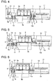
- position of the terminal-attached electric wire 14a (refer to Fig. 4 ), which have been respectively crimped at both ends where the jacket has been stripped off at the terminal crimping section 6, is fixed in up-down and left-right direction at the terminal-position regulating section 7 at the next step, and is passed on to the terminal-inserting hand 11a.
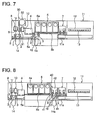
- the terminal-inserting hand 11a is a robot having X-Y-Z axes and after fixing the position of the electric wire 14a in up-down and left-right direction, it holds and conveys the terminal-attached electric wire 14a from the position shown in Fig. 4 to the position shown in Fig. 5 .
- the terminal-inserting hand 11a inserts the terminals of the terminal-attached electric wire 14a in the connector housing 13 which is placed in the connector receiving jig 12 positioned in the terminal-inserting section 11.
- the electric wire 14 is fed by a fixed amount at the electric wire measurement section 8 and the electric wire 14 is passed into a U-turn mechanism (not illustrated), and thereby, the downstream side terminal of the electric wire 14 is made to do a U-turn and then held with the electric wire holding hand 1. Thereafter, the electric wire 14 is measured and fed at the electric wire measurement section 8. After the measurement ends, the electric wire 14 is cut by a cutter 9 and its upstream side terminal is held with the electric wire holding hand 1. At this point, both ends of the electric wire 14 which has been measured and cut are held with the electric wire holding hand 1 and form a U-shape. The wire is conveyed to each process section in this form.
- terminals are crimped at both ends by the first terminal crimping pressing device 6a among the four terminal crimping pressing devices 6a.
- the advancement actuator 15 moves (advances) the two electric wire holding hands 3, 3 provided in the second electric wire conveying hand 2 to the crimp working position of the terminal crimping pressing device 6a, and thereby, the terminals are crimped.
- position of the terminal-attached electric wire 14a which have been crimped the terminals at its ends is fixed in up-down and left-right direction, and passed on to the terminal-inserting hand 11a.
- the terminal-inserting hand 11a After the terminal-inserting hand 11a fixed the position of the terminal-attached electric wire 14a at the terminal-position regulating section 7 in up-down and left-right direction at a position shown in Fig. 4 , it conveys the terminal-attached electric wire 14a to the terminal-inserting section 11 shown in Fig. 5 , and inserts the terminals of the terminal-attached electric wire 14a (e.g., female terminal section of the terminals) into the connector housing 13 placed in the connector receiving jig 12.
- the terminal-attached electric wire 14a e.g., female terminal section of the terminals
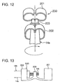
- Fig. 12 and Fig. 13 depicts a typical terminal-attached electric wire 14a in which terminals 200 have been respectively crimped at both ends.
- symbol 14b indicates insulating sheath of the electric wire 14
- symbol 14c indicates a plurality of core wires (conductor exposed section) whose insulating sheath 14b has been stripped off for a predetermined length from end of the electric wire 14 at the stripping section 10.
- Fig. 12 and Fig. 13 depicts a typical terminal-attached electric wire 14a in which terminals 200 have been respectively crimped at both ends.
- symbol 14b indicates insulating sheath of the electric wire 14
- symbol 14c indicates a plurality of core wires (conductor exposed section) whose insulating sheath 14b has been stripped off for a predetermined length from end of the electric wire 14 at the stripping section 10.
- the symbol 201 indicates a female terminal section of the terminal 200 and symbol 202 indicates an insulation barrel crimped to the insulation sheath 14b at the terminal crimping section 6, and symbol 203 indicates a wire barrel crimped to the core wires 14c at the terminal crimping section 6.
- the female terminal section 201 of the terminal 200 is inserted by a male terminal section of the connector housing 13 and it is electrically connected to the male terminal section.
- the first electric wire conveying hand 1 that respectively holds both ends of the electric wire 14 with the two electric wire holding hands 3 is moved from the electric wire measurement section 8 to the stripping section 10 by means of the first conveying operation actuator 5a, and after the stripping section 10, as shown in Fig. 4 , it passes the electric wire 14 to the grip-substituting hand 4 right before the terminal crimping section 6, and returns to the electric wire measurement section 8 driven by the first conveying operation actuator 5a.
- the electric wire 14 which is passed on from the first electric wire conveying hand 1 and held with the grip-substituting hand 4 is passed on to the second electric wire conveying hand 2 at a position shown in Fig. 4 .
- both ends of the electric wire 14 are respectively held with the two electric wire holding hands 3 of the second electric wire conveying hand 2 at a position shown in Fig. 4 .
- the second electric wire conveying hand 2 that respectively holds both ends of the electric wire 14 with the two electric wire holding hands 3 is driven by the second conveying operation actuator 5b, and it is moved so that the right end of the electric wire 14 is placed at the installation location of the first terminal crimping pressing device 6a specified among the four terminal crimping pressing devices 6a (refer to Fig. 1 ).
- the advancement actuator 15 on the right as shown in Fig. 2 moves the right electric wire holding hand 3, which holds right end of the electric wire 14 to the crimp working location of the first terminal crimping pressing device 6a in a vertical direction.
- the terminal is crimped at right end of the electric wire 14 by means of the terminal crimping pressing device 6a at this location.
- the right advancement actuator 15 removes the right electric wire holding hand 3 from the crimp working location.
- the second electric wire conveying hand 2 is driven by the second conveying operation actuator 5b in a situation in which the hand respectively continues to hold both ends of the electric wire 14 with the two electric wire holding hands 3, and is moved so that left end of the electric wire 14 is placed at the installation location of a first terminal crimping pressing device 6a.
- the left advancement actuator 15 as shown in Fig. 2 moves the left electric wire holding hand 3 which holds left end of the electric wire 14 to the crimp working location of the first terminal crimping pressing device 6a in a vertical direction.
- the terminal is crimped at left end of the electric wire 14 by means of the terminal crimping pressing device 6a.
- the advancement actuator 15 on the left side removes the left electric wire holding hand 3 from the crimp working location.
- the terminal-attached electric wire 14a in which terminals have been crimped at both ends by means of the terminal crimping pressing device 6a is moved from a position where the left end of the electric wire 14 is positioned in the installation position of the first terminal crimping pressing device 6a to the position shown in Fig. 4 , driven by the second conveying operation actuator 5b.
- the terminal-attached electric wire 14a that is conveyed to the position shown in Fig. 4 is passed from the second electric wire conveying hand 2 to the terminal-inserting hand 11a.
- the second electric wire conveying hand 2 which has ceased holding the terminal-attached electric wire 14a returns from the position shown in Fig. 4 to the position shown in Fig. 1 .
- the electric wire is conveyed from the upstream process (electric wire measurement section 8) in which the electric wire is measured to the final process at the terminal-inserting section 11 in which the terminal-attached electric wire 14a is inserted in the connector housing 13.
- direction of the axis itself of the electric wire may change and a situation may arise in which terminal crimping fails.
- change in posture of the electric wire that could be regulated well may occur right before inserting the terminal of the terminal-attached electric wire 140a into the connector housing 130.
- the electric wire conveying means 18 conveys the electric wire 14 from one side of the plurality of terminal crimping pressing device 6a to another side without the electric wire 14 being grip-substituted, there is no change in posture of the terminal position after the terminals are crimped.
- the terminal crimping is unable due to changes in direction of the axis of the electric wire, or a situation where changes in posture that cannot be regulated well occur right before inserting the terminal of the terminal-attached electric wire 14a into the connector housing.
- terminal-attached electric wire 14a can be provided to the terminal-inserting section 11 with stability, and it is able to prevent defective products arising from changes in posture of the terminal.
- the electric wire 14 is moved from the stripping section 10 to the terminal crimping section 6 and terminal crimping process is performed for the electric wire 14 by the terminal crimping pressing device 6a as well, in a situation in which both ends of the wire are respectively held with the two electric wire holding hands 3 of the second electric wire conveying hand 2.
- the terminal-attached electric wire 14a that underwent the terminal crimping process is moved to the position shown in Fig. 4 driven by the second conveying operation actuator 5b, in a situation where both ends of the wire are respectively held with the two electric wire holding hands 3 of the second electric wire conveying hand 2. In this position, the terminal-attached electric wire 14 is passed from the second electric wire conveying hand 2 to the terminal-inserting hand 11a.
- the electric wire is not released nor substituted at the terminal crimping section 6.
- the second electric wire conveying hand 2 of the electric wire conveying means 18 conveys the electric wire from one side of the plurality of terminal crimping pressing devices 6a to another side without the electric wire being grip-substituted, and thereby, there is no change in posture of the terminal after the terminal is crimped.
- it is able to prevent a situation where there is a change in direction of the axis of the electric wire which makes the terminal crimping failure, or a situation where changes in posture that cannot be regulated well occur right before inserting the terminal of the terminal-attached electric wire into the connector housing.
- the terminal-attached electric wire can be provided to the terminal-inserting section with stability, and it is able to prevent defective products arising from the changes in posture of the terminal.
- Two electric wire holding hands 3 are respectively provided in the first electric wire conveying hand 1 and the second electric wire conveying hand 2 for holding both ends of the electric wire 14, and thereby, only four electric wire holding hands 3 are needed.
- the structure can be simplified and faults in the mechanism can be reduced due to the simple structure.
- the two electric wire holding hands 3, 3 which are provided in the second electric wire conveying hand 2 are each provided with an advancement actuator 15 which moves the electric wire holding hands 3 to the crimp-working location of the terminal crimping pressing device 6a in a direction perpendicular to the direction in which the electric wire 14 is conveyed.
- moving distance of the terminal crimping pressing device 6a towards the crimp-working location can be suitably set with the advancement actuators 15 respectively provided in the two electric wire holding hands 3 of the second electric wire conveying hand 2, and thereby, changing the advancing distance towards the crimp-working location becomes easy in case of change in the terminal. For example, it will be easier to deal with in a situation where there are several specifications for products manufactured with the device and where the terminals to be crimped are changed when manufacturing is done by interchanging the stages and correspondingly the distance for which the electric wire advances also changes.
- the advancement actuators 15 may be provided one for two the electric wire holding hands 3, i.e., two advancement actuators 15 in total. Thereby, it is not necessary to provide with the advancement actuators 15 one for each of the plurality of terminal crimping pressing devices 6a. This results in simplification of the mechanism.
- the electric wire terminal crimping device is configured such that the electric wire 14 and the terminal-attached electric wire 14a is conveyed by an electric wire conveying hand 1' from the electric wire measurement section 8 to the terminal-position regulating section 11. Therefore, in the present embodiment, comparing with the above first embodiment, the grip-substituting hand 4 is eliminated and a single electric wire conveying hand 1' is provided replacing the above-described two electric wire conveying hands 1 and 2. Moreover, a single conveying operation actuator 5b' which reciprocates the electric wire conveying hand 1' between the electric wire measurement section 8 and the terminal-position regulating section 11 is provided replacing the two conveying operation actuators 5a and 5b which drive the two electric wire conveying hands 1 and 2.
- the remaining configuration of the second embodiment is similar to that of the first embodiment.
- the second embodiment configured as such has the following functions and advantageous effects in addition to those of the first embodiment.
- the electric wire terminal crimping device is provided with a waterproof-rubber-plug insertion segment 30 between the electric wire measurement segment 8 and the stripping segment 10 in the first embodiment.
- the waterproof-rubber-plug insertion segment 30 is provided with a rubber Plug insertion unit 31 and a parts feeder 32. The arrangement for other parts is identical to that of the first embodiment.
- waterproof rubber plugs supplied from the parts feeder 32 are inserted in vicinity of both ends of the electric wire 14, respectively.
- the waterproof rubber plug improves waterproofing performance by blocking a space between outer-circumference surface near the terminals crimped at both ends of the terminal-attached electric wire 14a and inner-circumference surface of the electric wire passage hole of the connector housing 13.
- a wire harness assembly with improved waterproofing performance can be made since waterproof rubber plugs can be inserted respectively near both ends of the electric wire 14 by means of the waterproof-rubber-plug insertion segment 30 installed between the electric wire measurement segment 8 and the stripping segment 10.
- the electric wire terminal crimping device is additionally provided with an image inspection segment 40 between the terminal crimping section 6 and the terminal-position regulation segment 7 for inspecting terminal crimping condition.
- the image inspection segment 40 is equipped with an imaging test unit 42 including two cameras 41, 41 for recording images for both ends of the terminal-attached electric wire 14a.
- the electric wire automatic ejection device is an electric wire automatic ejection device that performs cutting of the electric wire 14, terminal crimping on both ends of the electric wire 14, and ejection of the terminal-attached electric wire 14a, wherein the electric wire is conveyed in the terminal crimping section 6 where a plurality of terminal crimping pressing devices 6a is equipped, without the electric wire 14 or the terminal-attached electric wire 14a being grip-substituted.
- the electric wire automatic ejection device eliminated the terminal-insertion section 11 and is provided with an electric wire ejection segment 50.
- the terminal insertion hand 11a of the first embodiment has been replaced with an electric wire ejection unit 51 and an evacuation tray 52 for picking up and ejecting the terminal-attached electric wire 14a.
- the second electric wire conveying hand 2 moves to a location of a terminal crimping pressing device 6a equipped with terminals to be crimped, among four terminal crimping pressing devices 6a at the terminal crimping section 6, without stopping. Then, after the terminal crimping is completed, position of the terminal-attached electric wire 14a is fixed in up-down and left-right directions with the terminal insertion hand 11a, and thereafter, it is conveyed from the position shown in Fig. 4 to the position shown in Fig. 5 .
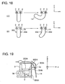
- Fig. 18(A) shows a behavior of the electric wire 14 upon the electric wire 14 moves from said one side to another side (Hereinafter, this direction is referred to as direction (x).).
- the U-shaped (loop-shaped) midsection area of the wire fails to follow the movement of the second electric wire conveying hand 2, and thereby, it gives rise to a phenomenon in which the wire is bent and is swung in opposite direction to the moving direction (x), as shown in right side of Fig. 18(A) .
- the electric wire 14 is bent and is swung as shown in right side of Fig. 18(A) with fulcrum point at a position held by the electric wire holding hands 3, 3.
- the faster the moving speed of the second electric wire conveying hand 2 the harder the electric wire 14 swings itself, and consequently, the swung electric wire 14 may coil-around the terminal crimping pressing device 6a and other mechanisms.
- the moving speed of the second electric wire conveying hand 2 can be set only in a range in which the swinging of the electric wire 14 becomes small, the conveying speed of the electric wire 14 cannot be made faster, and consequently, the device may not operate efficiently.
- similar phenomenon may arise even if the moving speed of the second electric wire conveying hand 2 is slow, and consequently, it may cause defective products such as damages to the electric wires, and equipment breakdown.
- the electric wire terminal crimping device is characterized in having the following arrangement.
- the electric wire terminal crimping device is comprised of: guide rods 302, 302 that act as electric wire anti-swinging units for regulating position of both sides of U-shaped (loop-shaped) electric wire 14; and actuators 303, 303 that act as anti-swinging unit driving means for driving the has been installed to conduct the position-control of both sides of the guide rods 302, 302.
- the guide rods 302, 302 regulate positions of both sides of the loop-shaped electric wire 14 at locations in outer side of the loop-shaped electric wire 14 with its both ends held with two electric wire holding hands 3 of the second electric wire conveying hand 2 so that the wire formed a loop-shape and are apart from locations where both ends of the wire are held with two electric wire holding hands 3 towards direction (y) shown in Fig. 14 .
- the actuators 303, 303 moves the guide rods 302, 302 between a first position (protrusive position shown in Figs. 16 and 17 ) located in a motion trajectory of the electric wire 14 upon the electric wire is conveyed between one side (left side) of the plurality of the terminal crimping pressing device 6a to another side (right side), and a second position (retracted position shown in Figs. 14 and 15 ) retracted from the motion trajectory.
- the electric wire terminal crimping device includes a cover 304 for protecting inner-structure of the second electric wire conveying hand 2, guide rods 302, 302, and actuators 303, 303.
- the cover 304 is provided with two through-holes 304a (refer to Fig. 14 ) for enabling movement of the guide rods 302, 302 between the first position and the second position.
- the guide rods 302, 302 are respectively configured to pass through the through-holes 304a of the cover 304 and to protrude from inner side to outer side at the first position, and thereby, regulate the position of both sides of the loop-shaped electric wire 14.
- the electric wire terminal crimping device includes a plate-shaped electric wire-guide 305 that acts as an electric wire guiding member allocated on the cover 304 with spacing from the cover 304.
- a plate-shaped electric wire-guide 305 that acts as an electric wire guiding member allocated on the cover 304 with spacing from the cover 304.
- the second electric wire conveying hand 2 moves to the grip-substituting hand 4 and receives the electric wire 14.
- the guide rods 302, 302 rise upwards driven by the actuator 303, pass through the through-holes 304a of the cover 304 and protrude to the outer side of the cover 304 (refer to Fig. 16 and Fig. 17 ), and guide outer side of the electric wire 14.
- the guide rods 302, 302 are positioned at locations farther from the end of the electric wire 14 compared with the two electric wire holding hands 3 of the second electric wire conveying hand 2, i.e., at locations apart from the electric wire holding hands 3 in right direction (direction (z)) that is center side of the loop-shaped electric wire 14 when viewed from the electric wire holding hands 3 in Fig. 14 .
- the second electric wire conveying hand 2 speedily moves from one side (left side) of the four terminal crimping pressing devices 6a to another side (right side), and after completing the terminal crimping process, the second electric wire conveying hand 2 speedily further moves to the terminal-position regulating section 7 side.
- the electric wire 14 passes through the gap (Dy) (as shown in Fig. 14 as a gap towards direction (y)) allocated above the guide rods 302, 302 (as shown in Fig. 14 at a location apart in direction (y)), between the electric wire guide 305 and the cover 304.
- the guide rods 302 moves downwards to the second position driven with the actuators 303, 303 and is positioned at inner side of the cover 304. Thereafter, the terminal-attached electric wire 14a is passed on to the terminal insertion hand 11 a, and the second electric wire conveying hand 2 returns to the grip-substituting hand 4 in a situation where the guide rods 302, 302 are moved downwards to the second position.
- the electric wire 14 or the terminal-attached electric wire 14a is swung up in an opposite direction to the moving direction (x).
- both sides of the U-shaped (loop-shaped) electric wire 14 is regulated by the guide rods 302, 302, and a fulcrum point where the electric wire 14 bends is located around the guide rods 302, 302 allocated at a location apart from a location where both ends of the electric wire 14 are held with the two electric wire holding hands 3 towards direction (y) in Fig. 14 , as shown in right side of Fig. 18(B) . Therefore, the rising of the electric wire in an opposite direction to the moving direction (x) is prevented. Thus, it is able to prevent the swung electric wire 14 or terminal-attached electric wire 14a from coiling around the terminal crimping pressing device 6a or other machine parts.
- the sixth embodiment configured as such accomplishes the following functions and advantageous effects in addition to those of the first embodiment.
- both sides of the U-shaped electric wire 14 is regulated by the guide rods 302, 302, and as shown in Fig. 18(B) on its right side, a fulcrum point where the electric wire 14 bends is located around the guide rods 302, 302 allocated at a location apart from a location where both ends of the electric wire 14 are held with the two electric wire holding hands 3 towards direction (y) in Fig. 14 .
- the electric wire 14 passes through the spacing (Dy) (refer to Fig. 14 ), which is located between the cover 304 and the electric wire guide 305, and by making the spacing (Dy) narrow to the extent the electric wire 14 can pass through it, the swinging of the electric wire 14 upwards above the cover 304 (towards direction (y)) is prevented by stopping it at the electric wire guide 305.
- the spacing (Dy) (refer to Fig. 14 ), which is located between the cover 304 and the electric wire guide 305, and by making the spacing (Dy) narrow to the extent the electric wire 14 can pass through it, the swinging of the electric wire 14 upwards above the cover 304 (towards direction (y)) is prevented by stopping it at the electric wire guide 305.
- the electric wire terminal crimping device includes a plate-shaped electric wire guide 305 that acts as an electric wire guiding member, allocated with spacing (Dy) (refer to Fig. 14 ) between itself and the cover 304 in front of 304, and wherein upon the electric wire 14 being conveyed between one side (left side) of the plurality of terminal crimping pressing device 6a and another side (right side), the electric wire passes through the spacing (Dy). Thereby, it is able to suppress the electric wire 14 from swinging upwards (in direction (y)) from the cover 304 by stopping at the electric wire guide 305.
- Dy spacing
- the electric wire terminal crimping device upon the electric wire 14 being conveyed, it is configured to further suppress the electric wire 14 from swinging upwards (in direction (y)) from the cover 304A.
- the device includes a plate-shaped electric wire guide 305A that acts as an electric wire guiding member, allocated with spacing (Dz) (refer to Fig. 19 ) between itself and the cover 304A on the cover 304A.
- Actuators 303A, 303A moves between a first position (a protrusive position shown in Fig. 20 ) which is located in motion trajectory of the electric wire 14 upon the electric wire 14 is conveyed between one side (left side) of the plurality of terminal crimping pressing device 6a and another side (right side), and a second position (a retracted position shown in Fig. 19 ) retracted from the motion trajectory, in direction (z).
- a first position a protrusive position shown in Fig. 20
- a second position a retracted position shown in Fig. 19
- the cover 304A for protecting inner structure of the second electric wire conveying hand 2 the guide rods 302A, 302A, and the actuators 303A, 303A is provided with two through-holes 304b for the guide rods 302A, 302A to move between the first position and the second position.
- Each of the guide rods 302A, 302A passes through the through-hole 304b to protrude from inner side to outer side, and thereby, performing regulation of the position of both sides of the loop-shaped electric wire 14.
- the seventh embodiment configured as such accomplishes the following functions and advantageous effects in addition to those of the sixth embodiment.
- the seventh embodiment is comprised of: guide rods 302A, 302A that acts as electric wire anti-swinging unit, for regulating the position of both sides of the U-shaped (loop-shaped) electric wire 14; and actuators 303A, 303A that acts as anti-swinging unit driving means, for driving the guide rods 302A, 302A.
- the electric wire terminal crimping device is further improved from that of the seventh embodiment and is characterized in the following points:
- the device uses a dish-shaped guiding member 307 comprised of: a bottom wall 308 for supporting the loop-shaped electric wire 14; and side walls 309, 310 capable of contacting both sides of the loop-shaped electric wire 14.
- the dish-shaped guiding member 307 is driven between a protrusive position where the electric wire 14 is supported with the bottom wall 308 and a retracted position retracted from the protrusive position, by an actuator 303B that acts as anti-swinging unit driving means.
- inner walls 311, 312 for regulating the position of both sides of the electric wire 14 cooperating with each of the side walls 309, 310 are provided on the bottom wall 308 of the dish-shaped guiding member 307.
- the eighth embodiment configured as such accomplishes the following functions and advantageous effects in addition to those of the seventh embodiment.
- Inner walls 311, 312 for regulating the position of both sides of the electric wire 14 cooperating with each of the side walls 309, 310 are provided on the bottom wall 308 of the dish-shaped guiding member 307. According to this arrangement, the position of one side of the electric wire 14 loop-shaped due to the side wall 309 and the inner wall 311 is regulated, and the position of another side of the electric wire loop-shaped due to the side wall 310 and the inner wall 312 is regulated as well. Thereby, the swinging of the electric wire 14 or the terminal-attached electric wire 14a in opposite direction to the moving direction (x) is further suppressed.
- a method for crimping terminals of an electric wire for cutting an electric wire and for crimping terminals to both ends of the electric wire wherein the electric wire is conveyed from one side of a plurality of electric wire crimping means to another side allocated in a row in conveying direction of the electric wire, without the electric wire being grip-substituted, and the conveyance of the electric wire is capable of being stopped at a discretional one of the plurality of electric wire crimping means.
- the method since the electric wire is conveyed from one side of a plurality of electric wire crimping means to another side, without the electric wire being grip-substituted, even if the number of the electric wire crimping means increased or the conveying speed of the electric wire became faster, the holding failure for the electric wire is suppressed and defective products arising from the holding failure is prevented. Further, since the electric wire is conveyed from one side of a plurality of electric wire crimping means to another side, without the electric wire being grip-substituted, changes in posture of the terminal is avoided after crimping the terminal, and a situation where changes in posture that cannot be regulated well right before inserting the terminal of the terminal-attached electric wire into the connector housing is avoided. Thereby, the terminal-attached electric wire can be provided to the terminal-inserting section with stability, and it is able to prevent defective products arising from changes in posture of the terminal.
- the present invention is applicable to the following method for crimping terminals of an electric wire:
- a method for crimping terminals of an electric wire comprised of the following steps carried out in this order: an electric wire measuring step for measuring an electric wire and cutting it in a predetermined length; a stripping step for stripping jacket at both ends of the electric wire; a terminal crimping step for crimping a terminal to an end of the electric wire; a terminal position regulating step for regulating position of the terminal of the terminal-attached electric wire; and a terminal inserting step for inserting the terminal-attached electric wire to a connector housing; and wherein in said terminal crimping step, the electric wire is conveyed from one side of a plurality of electric wire crimping means to another side allocated in a row in conveying direction of the electric wire, without the electric wire being grip-substituted, and the conveyance of the electric wire is capable of being stopped at a discretional one of the plurality of electric wire crimping means.
- the method since the electric wire is conveyed from one side of a plurality of electric wire crimping means to another side in the terminal crimping step, without the electric wire being grip-substituted, even if the number of the electric wire crimping means increased or the conveying speed of the electric wire became faster, the holding failure for the electric wire is suppressed and defective products arising from the holding failure is prevented. Further, since the electric wire is not grip-substituted in the terminal crimping step, the terminal-attached electric wire can be provided to the terminal inserting step with stability, and it is able to prevent defective products arising from changes in posture of the terminal.
- the device is able to deal with a plurality of types of rubber plugs by allocating a plurality of sets of the rubber plug inserting unit 31 and the parts feeder 32 and elongating the first conveying operation actuator 5a.
- the image inspection unit 42 for inspecting a condition of the crimping of the terminal is provided with two cameras 41, 41, both ends of the terminal-attached electric wire 14a may be recorded one end to the other sequentially using a single camera so that condition of the crimping of the terminal at its ends is inspected one end to the other sequentially.
- a terminal having female terminal section (refer to female terminal section 201 in Fig. 12 ) is crimped at both ends of the electric wire 14 and the female terminal section is inserted into the connector housing 13, and thereby the female terminal section is electrically connected with the male terminal section in the connector housing.
- the invention is not limited to such an arrangement. That is, the invention is applicable to cases where a terminal having male terminal section is crimped at both ends of the electric wire 14 and the male terminal section is inserted into the connector housing 13, and thereby the male terminal section is electrically connected with the female terminal section in the connector housing.
- positions for both sides of the loop-shaped electric wire are regulated.
- the invention is applicable to an electric wire terminal crimping device wherein a position for one side of the loop-shaped electric wire is regulated.
- the electric wire terminal crimping devices according to the sixth to eighth embodiments are applicable to electric wire terminal crimping devices having arrangements having the electric wire protecting cover 20 for preventing swinging of the electric wire 14 and the terminal-attached electric wire 14a described in the first embodiment, or having arrangements without the electric wire protecting cover 20.
Landscapes
- Engineering & Computer Science (AREA)
- Manufacturing & Machinery (AREA)
- Manufacturing Of Electrical Connectors (AREA)
Applications Claiming Priority (3)
| Application Number | Priority Date | Filing Date | Title |
|---|---|---|---|
| JP2006311439 | 2006-11-17 | ||
| JP2007072651A JP4934468B2 (ja) | 2006-11-17 | 2007-03-20 | 電線の端子圧着装置及び電線の端子圧着方法 |
| PCT/JP2007/072025 WO2008059845A1 (en) | 2006-11-17 | 2007-11-13 | Device and method for crimping electric wire terminal |
Publications (3)
| Publication Number | Publication Date |
|---|---|
| EP2088649A1 true EP2088649A1 (de) | 2009-08-12 |
| EP2088649A4 EP2088649A4 (de) | 2012-06-06 |
| EP2088649B1 EP2088649B1 (de) | 2017-05-10 |
Family
ID=39401652
Family Applications (1)
| Application Number | Title | Priority Date | Filing Date |
|---|---|---|---|
| EP07831755.9A Active EP2088649B1 (de) | 2006-11-17 | 2007-11-13 | Einrichtung und verfahren zum krimpen eines elektrischen drahtanschlusses |
Country Status (4)
| Country | Link |
|---|---|
| US (2) | US8266799B2 (de) |
| EP (1) | EP2088649B1 (de) |
| JP (1) | JP4934468B2 (de) |
| WO (1) | WO2008059845A1 (de) |
Cited By (5)
| Publication number | Priority date | Publication date | Assignee | Title |
|---|---|---|---|---|
| EP2565992A1 (de) * | 2011-08-31 | 2013-03-06 | Komax Holding AG | Einrichtung und Verfahren zur Zubringung von Kabelenden zu Konfektioniereinheiten |
| WO2016128892A1 (en) * | 2015-02-10 | 2016-08-18 | 4 Box Srl | Electrical device with terminal and wire-stripping seat |
| EP3327879A1 (de) * | 2016-11-23 | 2018-05-30 | Airbus Defence and Space SA | Vorrichtung und verfahren zur bearbeitung eines stromkabels |
| CN111029888A (zh) * | 2019-12-25 | 2020-04-17 | 嘉兴君权自动化设备有限公司 | 一种电缆端头处理生产线 |
| WO2022195325A1 (de) | 2021-03-17 | 2022-09-22 | Schleuniger Ag | Kabelbearbeitung mit zu- und abfuhr |
Families Citing this family (10)
| Publication number | Priority date | Publication date | Assignee | Title |
|---|---|---|---|---|
| JP5390921B2 (ja) * | 2009-04-20 | 2014-01-15 | 古河電気工業株式会社 | 電線端末処理装置 |
| EP2421102B1 (de) * | 2010-08-19 | 2018-06-06 | Komax Holding AG | Vorrichtung und Verfahren zum Bilden einer Kabelschlaufe |
| JP5613035B2 (ja) * | 2010-12-10 | 2014-10-22 | 矢崎総業株式会社 | 電線搬送装置及び電線搬送方法 |
| JP5827886B2 (ja) * | 2011-12-19 | 2015-12-02 | 矢崎総業株式会社 | 電線搬送方法 |
| CN107962366B (zh) * | 2017-11-20 | 2023-05-09 | 采埃孚富奥底盘技术(长春)有限公司 | 一种防错装配工装 |
| DE102018131439A1 (de) * | 2018-05-04 | 2019-11-07 | Weidmüller Interface GmbH & Co. KG | Modulares Kabelverarbeitungscenter |
| US12343764B2 (en) * | 2019-05-30 | 2025-07-01 | Shinmaywa Industries, Ltd. | Electric wire processing apparatus |
| US20240120697A1 (en) * | 2020-12-07 | 2024-04-11 | Polygon T.R Ltd. | Systems and methods for automatic electrical wiring |
| KR102702844B1 (ko) * | 2021-12-28 | 2024-09-04 | 주식회사 유라코퍼레이션 | 전선 압착용 장치 |
| CN115986527B (zh) * | 2022-12-05 | 2026-04-07 | 湖南永锐科技股份有限公司 | 一种液控式线缆加工系统 |
Family Cites Families (14)
| Publication number | Priority date | Publication date | Assignee | Title |
|---|---|---|---|---|
| US3707756A (en) * | 1971-02-12 | 1973-01-02 | Thomas & Betts Corp | Wire positioner for terminal attaching machine |
| GB1493713A (en) * | 1974-09-12 | 1977-11-30 | Aluminum Co Of America | Electrical connectors and multi-strand cables and method of using the same |
| JPS5155980U (de) * | 1974-10-25 | 1976-04-30 | ||
| JP3056353B2 (ja) | 1992-12-04 | 2000-06-26 | 矢崎総業株式会社 | ワイヤハーネスのセット式製造方法および製造装置 |
| JP2830894B2 (ja) | 1993-07-08 | 1998-12-02 | 矢崎総業株式会社 | ハーネスサブアッシーの製造方法 |
| JP2987542B2 (ja) | 1994-02-25 | 1999-12-06 | 矢崎総業株式会社 | Uターン検尺する長尺電線の処理方法及びその装置 |
| JP3141985B2 (ja) * | 1995-12-13 | 2001-03-07 | 矢崎総業株式会社 | 電線処理装置における電線移送装置および電線移送方法 |
| JP3632937B2 (ja) * | 1996-05-20 | 2005-03-30 | 矢崎総業株式会社 | ハーネス製造方法と圧接機及びコネクタ保持竿並びに圧接装置 |
| JP3892919B2 (ja) * | 1996-10-03 | 2007-03-14 | 矢崎総業株式会社 | ワイヤハーネスの製造方法及び製造装置 |
| JP3523086B2 (ja) * | 1998-10-14 | 2004-04-26 | 矢崎総業株式会社 | 電線出寸法の調整装置及び調整方法 |
| US6612026B1 (en) * | 1999-05-24 | 2003-09-02 | Sumitomo Wiring Systems, Ltd. | Process for mounting terminals with electric wires in cavities of connector housings |
| US6961996B2 (en) * | 2001-04-10 | 2005-11-08 | Komax Holding Ag | Method for installing cable ends in plug housings |
| EP1461179B1 (de) * | 2001-11-24 | 2016-01-20 | Delphi Technologies, Inc. | Verbesserungen bei kabelbäumen |
| JP5155980B2 (ja) | 2009-10-23 | 2013-03-06 | 三菱重工業株式会社 | ターボコンパウンドシステムおよびその運転方法 |
-
2007
- 2007-03-20 JP JP2007072651A patent/JP4934468B2/ja active Active
- 2007-11-13 WO PCT/JP2007/072025 patent/WO2008059845A1/ja not_active Ceased
- 2007-11-13 EP EP07831755.9A patent/EP2088649B1/de active Active
-
2009
- 2009-05-14 US US12/465,690 patent/US8266799B2/en active Active
-
2012
- 2012-08-16 US US13/587,475 patent/US8671558B2/en active Active
Cited By (8)
| Publication number | Priority date | Publication date | Assignee | Title |
|---|---|---|---|---|
| EP2565992A1 (de) * | 2011-08-31 | 2013-03-06 | Komax Holding AG | Einrichtung und Verfahren zur Zubringung von Kabelenden zu Konfektioniereinheiten |
| US9124058B2 (en) | 2011-08-31 | 2015-09-01 | Komax Holding Ag | Feeding wire-ends to processing units |
| WO2016128892A1 (en) * | 2015-02-10 | 2016-08-18 | 4 Box Srl | Electrical device with terminal and wire-stripping seat |
| CN107408788A (zh) * | 2015-02-10 | 2017-11-28 | 4博克斯有限公司 | 具有端子和导线剥离座的电气设备 |
| US10008818B2 (en) | 2015-02-10 | 2018-06-26 | 4 Box Srl | Electrical device with terminal and wire-stripping seat |
| EP3327879A1 (de) * | 2016-11-23 | 2018-05-30 | Airbus Defence and Space SA | Vorrichtung und verfahren zur bearbeitung eines stromkabels |
| CN111029888A (zh) * | 2019-12-25 | 2020-04-17 | 嘉兴君权自动化设备有限公司 | 一种电缆端头处理生产线 |
| WO2022195325A1 (de) | 2021-03-17 | 2022-09-22 | Schleuniger Ag | Kabelbearbeitung mit zu- und abfuhr |
Also Published As
| Publication number | Publication date |
|---|---|
| WO2008059845A1 (en) | 2008-05-22 |
| EP2088649A4 (de) | 2012-06-06 |
| US20090235522A1 (en) | 2009-09-24 |
| US8671558B2 (en) | 2014-03-18 |
| US20120304461A1 (en) | 2012-12-06 |
| JP2008147152A (ja) | 2008-06-26 |
| EP2088649B1 (de) | 2017-05-10 |
| JP4934468B2 (ja) | 2012-05-16 |
| US8266799B2 (en) | 2012-09-18 |
Similar Documents
| Publication | Publication Date | Title |
|---|---|---|
| US8266799B2 (en) | Method for crimping electric wire terminal | |
| JP7133325B2 (ja) | はんだスリーブを取り上げ、シールドされた電気ワイヤー及びケーブルに設置して溶かすための装置、システム、及び方法 | |
| JP7779840B2 (ja) | ケーブル処理ステーション、ケーブル処理ステーションを有するケーブル機械、およびコンピュータ実行方法 | |
| JP2014007043A (ja) | 電線皮むき方法及び装置、並びに端子電線圧着方法及び装置 | |
| JP6801567B2 (ja) | 撚りほどき装置および電線端部加工装置 | |
| US20150372437A1 (en) | Terminal crimping machine having a wire clamp | |
| EP0330309A2 (de) | Quetschkabelbaum-Herstellungsapparat und -Methode | |
| WO2015156793A1 (en) | Automatic terminated wire lead insertion machine and method of operating said machine | |
| CN110416844B (zh) | 具有可移除外部负载条的电连接器及其使用方法 | |
| US20260058428A1 (en) | Multicore cable processing apparatus | |
| US5933932A (en) | Apparatus for making electrical harness | |
| WO2015193248A1 (de) | Vorrichtung und verfahren zum automatischen bestücken eines steckergehäuses | |
| DE102009027967A1 (de) | Verfahren und Vorrichtung zur Überwachung der Abisolierung von Leitungsenden | |
| US11283230B2 (en) | Device, method, and system for inverse crimping | |
| JPH10172712A (ja) | ワイヤ圧着ハーネスの製造装置と方法 | |
| CN115224562A (zh) | 压接装置以及用于压接压接套筒的方法 | |
| CN110581423A (zh) | 端子压接装置和端子压接方法 | |
| US20260058038A1 (en) | Device and method for processing a plurality of electrical wires | |
| CN223296577U (zh) | 一种长短线结构线束的打端绞线设备 | |
| JPH04179083A (ja) | 電線の端末心線折り曲げ装置 | |
| JPH09213146A (ja) | 押出し被覆による多芯平角電線の製造方法および製造装置 | |
| EP4604336A1 (de) | Mehradrige abgeschirmte kabelbearbeitungsvorrichtung | |
| EP4412014B1 (de) | Vorrichtung zur ausrichtung der kernleitung für mehradriges kabel | |
| KR100586687B1 (ko) | 케이블 공급장치 | |
| HK40016327B (en) | Electrical connector with removable external load bar, and method of its use |
Legal Events
| Date | Code | Title | Description |
|---|---|---|---|
| PUAI | Public reference made under article 153(3) epc to a published international application that has entered the european phase |
Free format text: ORIGINAL CODE: 0009012 |
|
| 17P | Request for examination filed |
Effective date: 20090514 |
|
| AK | Designated contracting states |
Kind code of ref document: A1 Designated state(s): AT BE BG CH CY CZ DE DK EE ES FI FR GB GR HU IE IS IT LI LT LU LV MC MT NL PL PT RO SE SI SK TR |
|
| DAX | Request for extension of the european patent (deleted) | ||
| A4 | Supplementary search report drawn up and despatched |
Effective date: 20120507 |
|
| RIC1 | Information provided on ipc code assigned before grant |
Ipc: H01R 43/052 20060101AFI20120427BHEP Ipc: H01R 43/28 20060101ALI20120427BHEP Ipc: H01R 43/048 20060101ALI20120427BHEP |
|
| 17Q | First examination report despatched |
Effective date: 20140212 |
|
| GRAP | Despatch of communication of intention to grant a patent |
Free format text: ORIGINAL CODE: EPIDOSNIGR1 |
|
| INTG | Intention to grant announced |
Effective date: 20161014 |
|
| GRAS | Grant fee paid |
Free format text: ORIGINAL CODE: EPIDOSNIGR3 |
|
| STAA | Information on the status of an ep patent application or granted ep patent |
Free format text: STATUS: GRANT OF PATENT IS INTENDED |
|
| GRAJ | Information related to disapproval of communication of intention to grant by the applicant or resumption of examination proceedings by the epo deleted |
Free format text: ORIGINAL CODE: EPIDOSDIGR1 |
|
| GRAL | Information related to payment of fee for publishing/printing deleted |
Free format text: ORIGINAL CODE: EPIDOSDIGR3 |
|
| STAA | Information on the status of an ep patent application or granted ep patent |
Free format text: STATUS: EXAMINATION IS IN PROGRESS |
|
| GRAP | Despatch of communication of intention to grant a patent |
Free format text: ORIGINAL CODE: EPIDOSNIGR1 |
|
| STAA | Information on the status of an ep patent application or granted ep patent |
Free format text: STATUS: GRANT OF PATENT IS INTENDED |
|
| INTC | Intention to grant announced (deleted) | ||
| GRAA | (expected) grant |
Free format text: ORIGINAL CODE: 0009210 |
|
| STAA | Information on the status of an ep patent application or granted ep patent |
Free format text: STATUS: THE PATENT HAS BEEN GRANTED |
|
| INTG | Intention to grant announced |
Effective date: 20170322 |
|
| AK | Designated contracting states |
Kind code of ref document: B1 Designated state(s): AT BE BG CH CY CZ DE DK EE ES FI FR GB GR HU IE IS IT LI LT LU LV MC MT NL PL PT RO SE SI SK TR |
|
| REG | Reference to a national code |
Ref country code: GB Ref legal event code: FG4D |
|
| REG | Reference to a national code |
Ref country code: AT Ref legal event code: REF Ref document number: 893235 Country of ref document: AT Kind code of ref document: T Effective date: 20170515 Ref country code: CH Ref legal event code: EP |
|
| REG | Reference to a national code |
Ref country code: IE Ref legal event code: FG4D |
|
| REG | Reference to a national code |
Ref country code: DE Ref legal event code: R096 Ref document number: 602007050973 Country of ref document: DE |
|
| REG | Reference to a national code |
Ref country code: NL Ref legal event code: MP Effective date: 20170510 |
|
| REG | Reference to a national code |
Ref country code: LT Ref legal event code: MG4D |
|
| REG | Reference to a national code |
Ref country code: AT Ref legal event code: MK05 Ref document number: 893235 Country of ref document: AT Kind code of ref document: T Effective date: 20170510 |
|
| PG25 | Lapsed in a contracting state [announced via postgrant information from national office to epo] |
Ref country code: FI Free format text: LAPSE BECAUSE OF FAILURE TO SUBMIT A TRANSLATION OF THE DESCRIPTION OR TO PAY THE FEE WITHIN THE PRESCRIBED TIME-LIMIT Effective date: 20170510 Ref country code: AT Free format text: LAPSE BECAUSE OF FAILURE TO SUBMIT A TRANSLATION OF THE DESCRIPTION OR TO PAY THE FEE WITHIN THE PRESCRIBED TIME-LIMIT Effective date: 20170510 Ref country code: ES Free format text: LAPSE BECAUSE OF FAILURE TO SUBMIT A TRANSLATION OF THE DESCRIPTION OR TO PAY THE FEE WITHIN THE PRESCRIBED TIME-LIMIT Effective date: 20170510 Ref country code: LT Free format text: LAPSE BECAUSE OF FAILURE TO SUBMIT A TRANSLATION OF THE DESCRIPTION OR TO PAY THE FEE WITHIN THE PRESCRIBED TIME-LIMIT Effective date: 20170510 Ref country code: GR Free format text: LAPSE BECAUSE OF FAILURE TO SUBMIT A TRANSLATION OF THE DESCRIPTION OR TO PAY THE FEE WITHIN THE PRESCRIBED TIME-LIMIT Effective date: 20170811 |
|
| PG25 | Lapsed in a contracting state [announced via postgrant information from national office to epo] |
Ref country code: BG Free format text: LAPSE BECAUSE OF FAILURE TO SUBMIT A TRANSLATION OF THE DESCRIPTION OR TO PAY THE FEE WITHIN THE PRESCRIBED TIME-LIMIT Effective date: 20170810 Ref country code: PL Free format text: LAPSE BECAUSE OF FAILURE TO SUBMIT A TRANSLATION OF THE DESCRIPTION OR TO PAY THE FEE WITHIN THE PRESCRIBED TIME-LIMIT Effective date: 20170510 Ref country code: SE Free format text: LAPSE BECAUSE OF FAILURE TO SUBMIT A TRANSLATION OF THE DESCRIPTION OR TO PAY THE FEE WITHIN THE PRESCRIBED TIME-LIMIT Effective date: 20170510 Ref country code: NL Free format text: LAPSE BECAUSE OF FAILURE TO SUBMIT A TRANSLATION OF THE DESCRIPTION OR TO PAY THE FEE WITHIN THE PRESCRIBED TIME-LIMIT Effective date: 20170510 Ref country code: IS Free format text: LAPSE BECAUSE OF FAILURE TO SUBMIT A TRANSLATION OF THE DESCRIPTION OR TO PAY THE FEE WITHIN THE PRESCRIBED TIME-LIMIT Effective date: 20170910 Ref country code: LV Free format text: LAPSE BECAUSE OF FAILURE TO SUBMIT A TRANSLATION OF THE DESCRIPTION OR TO PAY THE FEE WITHIN THE PRESCRIBED TIME-LIMIT Effective date: 20170510 |
|
| PG25 | Lapsed in a contracting state [announced via postgrant information from national office to epo] |
Ref country code: DK Free format text: LAPSE BECAUSE OF FAILURE TO SUBMIT A TRANSLATION OF THE DESCRIPTION OR TO PAY THE FEE WITHIN THE PRESCRIBED TIME-LIMIT Effective date: 20170510 Ref country code: SK Free format text: LAPSE BECAUSE OF FAILURE TO SUBMIT A TRANSLATION OF THE DESCRIPTION OR TO PAY THE FEE WITHIN THE PRESCRIBED TIME-LIMIT Effective date: 20170510 Ref country code: RO Free format text: LAPSE BECAUSE OF FAILURE TO SUBMIT A TRANSLATION OF THE DESCRIPTION OR TO PAY THE FEE WITHIN THE PRESCRIBED TIME-LIMIT Effective date: 20170510 Ref country code: EE Free format text: LAPSE BECAUSE OF FAILURE TO SUBMIT A TRANSLATION OF THE DESCRIPTION OR TO PAY THE FEE WITHIN THE PRESCRIBED TIME-LIMIT Effective date: 20170510 Ref country code: CZ Free format text: LAPSE BECAUSE OF FAILURE TO SUBMIT A TRANSLATION OF THE DESCRIPTION OR TO PAY THE FEE WITHIN THE PRESCRIBED TIME-LIMIT Effective date: 20170510 |
|
| REG | Reference to a national code |
Ref country code: DE Ref legal event code: R097 Ref document number: 602007050973 Country of ref document: DE |
|
| PG25 | Lapsed in a contracting state [announced via postgrant information from national office to epo] |
Ref country code: IT Free format text: LAPSE BECAUSE OF FAILURE TO SUBMIT A TRANSLATION OF THE DESCRIPTION OR TO PAY THE FEE WITHIN THE PRESCRIBED TIME-LIMIT Effective date: 20170510 |
|
| PLBE | No opposition filed within time limit |
Free format text: ORIGINAL CODE: 0009261 |
|
| STAA | Information on the status of an ep patent application or granted ep patent |
Free format text: STATUS: NO OPPOSITION FILED WITHIN TIME LIMIT |
|
| 26N | No opposition filed |
Effective date: 20180213 |
|
| PG25 | Lapsed in a contracting state [announced via postgrant information from national office to epo] |
Ref country code: SI Free format text: LAPSE BECAUSE OF FAILURE TO SUBMIT A TRANSLATION OF THE DESCRIPTION OR TO PAY THE FEE WITHIN THE PRESCRIBED TIME-LIMIT Effective date: 20170510 |
|
| PG25 | Lapsed in a contracting state [announced via postgrant information from national office to epo] |
Ref country code: MC Free format text: LAPSE BECAUSE OF FAILURE TO SUBMIT A TRANSLATION OF THE DESCRIPTION OR TO PAY THE FEE WITHIN THE PRESCRIBED TIME-LIMIT Effective date: 20170510 |
|
| GBPC | Gb: european patent ceased through non-payment of renewal fee |
Effective date: 20171113 |
|
| PG25 | Lapsed in a contracting state [announced via postgrant information from national office to epo] |
Ref country code: LI Free format text: LAPSE BECAUSE OF NON-PAYMENT OF DUE FEES Effective date: 20171130 Ref country code: CH Free format text: LAPSE BECAUSE OF NON-PAYMENT OF DUE FEES Effective date: 20171130 |
|
| PG25 | Lapsed in a contracting state [announced via postgrant information from national office to epo] |
Ref country code: LU Free format text: LAPSE BECAUSE OF NON-PAYMENT OF DUE FEES Effective date: 20171113 |
|
| REG | Reference to a national code |
Ref country code: FR Ref legal event code: ST Effective date: 20180731 Ref country code: BE Ref legal event code: MM Effective date: 20171130 |
|
| REG | Reference to a national code |
Ref country code: IE Ref legal event code: MM4A |
|
| PG25 | Lapsed in a contracting state [announced via postgrant information from national office to epo] |
Ref country code: MT Free format text: LAPSE BECAUSE OF NON-PAYMENT OF DUE FEES Effective date: 20171113 |
|
| PG25 | Lapsed in a contracting state [announced via postgrant information from national office to epo] |
Ref country code: IE Free format text: LAPSE BECAUSE OF NON-PAYMENT OF DUE FEES Effective date: 20171113 Ref country code: FR Free format text: LAPSE BECAUSE OF NON-PAYMENT OF DUE FEES Effective date: 20171130 |
|
| PG25 | Lapsed in a contracting state [announced via postgrant information from national office to epo] |
Ref country code: GB Free format text: LAPSE BECAUSE OF NON-PAYMENT OF DUE FEES Effective date: 20171113 Ref country code: BE Free format text: LAPSE BECAUSE OF NON-PAYMENT OF DUE FEES Effective date: 20171130 |
|
| PG25 | Lapsed in a contracting state [announced via postgrant information from national office to epo] |
Ref country code: HU Free format text: LAPSE BECAUSE OF FAILURE TO SUBMIT A TRANSLATION OF THE DESCRIPTION OR TO PAY THE FEE WITHIN THE PRESCRIBED TIME-LIMIT; INVALID AB INITIO Effective date: 20071113 |
|
| PG25 | Lapsed in a contracting state [announced via postgrant information from national office to epo] |
Ref country code: CY Free format text: LAPSE BECAUSE OF NON-PAYMENT OF DUE FEES Effective date: 20170510 |
|
| PG25 | Lapsed in a contracting state [announced via postgrant information from national office to epo] |
Ref country code: TR Free format text: LAPSE BECAUSE OF FAILURE TO SUBMIT A TRANSLATION OF THE DESCRIPTION OR TO PAY THE FEE WITHIN THE PRESCRIBED TIME-LIMIT Effective date: 20170510 |
|
| PG25 | Lapsed in a contracting state [announced via postgrant information from national office to epo] |
Ref country code: PT Free format text: LAPSE BECAUSE OF FAILURE TO SUBMIT A TRANSLATION OF THE DESCRIPTION OR TO PAY THE FEE WITHIN THE PRESCRIBED TIME-LIMIT Effective date: 20170510 |
|
| P01 | Opt-out of the competence of the unified patent court (upc) registered |
Effective date: 20230512 |
|
| PGFP | Annual fee paid to national office [announced via postgrant information from national office to epo] |
Ref country code: DE Payment date: 20250930 Year of fee payment: 19 |