EP2089193B1 - Préhenseur de pièces de tôlerie de taille et/ou de types différents - Google Patents
Préhenseur de pièces de tôlerie de taille et/ou de types différents Download PDFInfo
- Publication number
- EP2089193B1 EP2089193B1 EP07847759A EP07847759A EP2089193B1 EP 2089193 B1 EP2089193 B1 EP 2089193B1 EP 07847759 A EP07847759 A EP 07847759A EP 07847759 A EP07847759 A EP 07847759A EP 2089193 B1 EP2089193 B1 EP 2089193B1
- Authority
- EP
- European Patent Office
- Prior art keywords
- gripper
- sheet metal
- multifunction
- positioning
- central beam
- Prior art date
- Legal status (The legal status is an assumption and is not a legal conclusion. Google has not performed a legal analysis and makes no representation as to the accuracy of the status listed.)
- Not-in-force
Links
- 239000002184 metal Substances 0.000 title claims abstract description 9
- 238000004519 manufacturing process Methods 0.000 description 3
- 238000009412 basement excavation Methods 0.000 description 1
- 239000000872 buffer Substances 0.000 description 1
- 238000001514 detection method Methods 0.000 description 1
- 238000006073 displacement reaction Methods 0.000 description 1
- 238000003466 welding Methods 0.000 description 1
Images

Classifications
-
- B—PERFORMING OPERATIONS; TRANSPORTING
- B25—HAND TOOLS; PORTABLE POWER-DRIVEN TOOLS; MANIPULATORS
- B25J—MANIPULATORS; CHAMBERS PROVIDED WITH MANIPULATION DEVICES
- B25J15/00—Gripping heads and other end effectors
- B25J15/0052—Gripping heads and other end effectors multiple gripper units or multiple end effectors
-
- B—PERFORMING OPERATIONS; TRANSPORTING
- B25—HAND TOOLS; PORTABLE POWER-DRIVEN TOOLS; MANIPULATORS
- B25J—MANIPULATORS; CHAMBERS PROVIDED WITH MANIPULATION DEVICES
- B25J15/00—Gripping heads and other end effectors
- B25J15/0052—Gripping heads and other end effectors multiple gripper units or multiple end effectors
- B25J15/0061—Gripping heads and other end effectors multiple gripper units or multiple end effectors mounted on a modular gripping structure
Definitions
- the invention relates to the handling of sheets of which there are different sizes and types.
- motor vehicle door panels are thought of as part of a production or assembly line.
- FIG. 1 two different front vehicle door panels are shown in a superimposed manner to better show that they are of different types.
- the panel, referenced 1 is shorter and a little higher than the panel, referenced 2 (shown in broken lines).
- they have been represented in a position where one of their positioning holes, namely those referenced 3 and placed in the same region as each panel, are superimposed, that is to say, located in the same place.
- the second positioning hole that equips each of these panels is in different places.
- the second positioning hole 1A of the first panel 1 is closer to the common positioning hole 3 than the second positioning hole 2A of the panel 2.
- the main object of the invention is to overcome this disadvantage, to avoid building, for each type of vehicle door panel, a specific gripper.
- the main object of the invention is a gripper of sheet metal parts, of different size and / or type, each having two gripping holes, the gripper comprising a frame on which are mounted two multifunction devices, comprising each a positioning finger intended to each come in one of the two positioning holes of the sheet metal part, and gripping means of the sheet metal part.
- the gripper is characterized in that a first multifunction device is movable in translation on the chassis by means of translation and in that it comprises two anti-tilt supports placed on an end beam , on both sides of the second multifunction device.
- the preferred embodiment of the gripping means of the multifunction devices provides that they consist of two retractable fingers placed on both sides of the positioning finger.
- the preferred embodiment of the translation means of the first multifunction device consists of a linear actuator with ball guide.
- the gripper mainly comprises a frame on which are mounted the functional elements of the gripper.
- This frame consists of a central beam 10 constituting the main part of the frame. It is through it that the gripper will be carried by a handling robot, via a connecting member 16 placed below this central beam 10. At one end thereof is fixed, perpendicularly, a end beam 11, so that the assembly forms a T.
- the functional elements consist mainly of two multifunctional devices 12A and 12B.
- the first multifunction device 12A is mounted movable in longitudinal translation on the central beam 10, that is to say it can move along the longitudinal axis of the central beam 10.
- this translation is provided by a linear actuator 14, a fixed portion 14A of which is secured to a fixed structure 17, itself fixed to the end of the central beam 10 on the end beam 11.
- the other part of the actuator 14 is a part mobile 14B, which slides on the central beam 10, by means of translation bearings 18 the first multifunction device 12A.
- the second multifunction device 12B is fixedly mounted on the end beam 11, via the support structure 17.
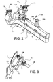
- the two multifunction devices 12A and 12B each have a positioning pin 13 projecting upwards in the position in which the gripper is represented on this figure 2 .
- the first multifunction device 12A is movable relative to the frame of the gripper, that is to say relative to the second multifunction device 12B, the distance between the two gripping fingers 13 of these two multifunction devices 12A and 12B is variable. Thus, it can adapt to the distance between two positioning holes 3, 1A and 2A, a vehicle door panel, as shown in FIG. figure 1 .
- the gripper according to the invention as described in this figure 2 , can adapt to different types of door panels to handle.
- these devices 12A and 12B are provided with gripping means to help capture and temporarily secure a door panel on the gripper.
- These gripping means are in fact constituted, for each of the multifunction devices 12A and 12B, two retractable fingers, not shown in these figures, but can project on demand, on either side of the positioning finger 13 and enter the excavations provided the panel to grasp, so as to secure the latter of the entire gripper.
- a panel may be grasped by the latter and moved, to the extent that the gripper is integral with a handling robot, not shown in this figure.
- the assembly is completed with two anti-tilt supports 15, each mounted at the end of the end beam 11, and whose buffers 18, placed on the upper part thereof, are at a height substantially less than that of the top of the gripping finger 13 of the second multifunction device 12B. They make it possible, when the gripper is in the positioning phase, that is to say when the positioning fingers 13 arrive in the positioning holes of the panel to be gripped, that the latter does not tip over and is immobilized in great part so that the grip can be done.
- the height of the pads 18 anti-tilt supports 15 is provided so that they come into contact with the panel, when the positioning finger 13 of the multifunction device 12B of the end beam 11 is in its positioning hole. Of course, this height must be adjustable according to the panel to enter.
- These two anti-tilt supports 15 also make it possible to compensate for the differences in positions of the door panels, related to the different forms thereof and prevent any tilting rotation thereof. They consist of units, themselves constituted of a jack guided with a rod blocker, equipped with a piece presence detection system. When approaching a room, namely a door panel, it is detected, and an information signal is sent to the control unit of the mounting station and / or welding so that it be locked in working position.
- the displacement length of the first multifunction device 12A is 500 mm, it can therefore be understood that the gripper can be adapted to a large number of different types of panels. manipulate.
- the figure 3 shows the gripper according to the invention, fixed on a robot 20, via a support member 16. It is shown schematically by the central beam 10 and the two multifunction devices 12A and 12B whose gripping finger has penetrated a panel of a vehicle door 1. It can be seen that, according to the movements of the robot, and in particular of its head 21, the panel can be manipulated in a space defined by the field of action of the robot 20. It can therefore be grasped at a location , the gripper using the variable distance between the two positioning fingers 13 of the two multifunction devices 12A and 12B to position themselves on the panel moved and rested at another location.
- the gripper according to the invention can therefore be used with many different types of door panels to be put in place on assembly lines or vehicle manufacturing of different types.
Landscapes
- Engineering & Computer Science (AREA)
- Robotics (AREA)
- Mechanical Engineering (AREA)
- Automobile Manufacture Line, Endless Track Vehicle, Trailer (AREA)
- Control And Other Processes For Unpacking Of Materials (AREA)
- Treatment Of Fiber Materials (AREA)
- Ultra Sonic Daignosis Equipment (AREA)
- Networks Using Active Elements (AREA)
- Load-Engaging Elements For Cranes (AREA)
- Feeding Of Articles By Means Other Than Belts Or Rollers (AREA)
- Manipulator (AREA)
Description
- L'invention concerne la manipulation de tôles dont il existe des tailles différentes et des types différents. On pense, en particulier, aux panneaux de portières de véhicules automobiles, dans le cadre d'une chaîne de fabrication ou de montage.
- Dans le cadre de la fabrication des portières de véhicules automobiles, il est nécessaire de manipuler des pièces de tôlerie, telles que des panneaux constituant, une fois assemblés avec d'autres pièces, une portière latérale.
- En effet, en se reportant à la
figure 1 , deux panneaux différents de portière avant de véhicule sont représentés de façon superposée pour mieux montrer qu'ils sont de types différents. Le panneau, référencé 1, est moins long et un peu plus haut que le panneau, référencé 2 (représenté en traits interrompus). Par contre, ils ont été représentés dans une position où un de leurs trous de positionnement, à savoir ceux référencés 3 et placés dans la même région que chaque panneau, sont superposés, c'est-à-dire situé au même endroit. Du fait que ces panneaux 1 et 2 sont de types différents, le deuxième trou de positionnement qui équipe chacun de ces panneaux se trouve à des endroits différents. En effet, le deuxième trou de positionnement 1A du premier panneau 1 se trouve plus près du trou de positionnement commun 3 que le deuxième trou de positionnement 2A du panneau 2. - Actuellement, pour manipuler ces panneaux de type différent, il est prévu, pour chaque type de panneau, de réaliser un ou plusieurs préhenseurs adaptés à chaque type de panneau de portière et pour chaque nouveau véhicule, comme décrit notamment dans les demandes de brevet
JP 2005-125456 JP 2004-148486 - En conséquence, le but principal de l'invention est de remédier à cet inconvénient, afin d'éviter de construire, pour chaque type de panneau de porte de véhicule, un préhenseur spécifique.
- A cet effet, l'objet principal de l'invention est un préhenseur de pièces de tôlerie, de taille et/ou de type différent, présentant chacune deux trous de préhension, le préhenseur comprenant un châssis sur lequel sont montés deux dispositifs multifonctions, comportant chacun un doigt de positionnement destiné à venir chacun dans un des deux trous de positionnement de la pièce de tôlerie, et des moyens de préhension de la pièce de tôlerie.
- Selon l'invention, le préhenseur est caractérisé en ce qu'un premier des dispositifs multifonctions est mobile en translation sur le châssis grâce à des moyens de translation et en ce qu'il comprend deux appuis anti-basculement placés sur une poutre d'extrémité, de part et d'autre du deuxième dispositif multifonction.
- Dans la réalisation envisagée du châssis, celui-ci comporté :
- une poutre centrale sur lequel le premier des deux dispositifs multifonctions est monté mobile le long de l'axe longitudinal de cette poutre centrale ; et
- une poutre d'extrémité placée perpendiculairement à une extrémité de la poutre centrale et sur laquelle est fixé le deuxième dispositif.
- La réalisation préférentielle des moyens de préhension des dispositifs multifonctions prévoit que ceux-ci soient constitués de deux doigts escamotables placés des deux côtés du doigt de positionnement.
- La réalisation préférentielle des moyens de translation du premier dispositif multifonction est constituée d'un actionneur linéaire à guidage à billes.
- L'invention et ses différentes caractéristiques techniques seront mieux comprises à la lecture de la description suivante, accompagnée de plusieurs figures représentant respectivement :
-
figure 1 , déjà décrite, deux panneaux de portière de véhicule automobile devant être manipulés par le préhenseur selon l'invention ; -
figure 2 , en vue cavalière, le préhenseur selon l'invention ; et -
figure 3 , en vue cavalière, l'utilisation du préhenseur selon l'invention sur un panneau de portière de véhicule automobile. - En référence à la
figure 2 , le préhenseur selon l'invention comprend principalement un châssis sur lequel sont montés les éléments fonctionnels du préhenseur. Ce châssis est constitué d'une poutre centrale 10 constituant la pièce principale du châssis. C'est par son intermédiaire que le préhenseur sera porté par un robot de manipulation, par l'intermédiaire d'un élément de liaison 16 placé en dessous de cette poutre centrale 10. A une extrémité de celle-ci est fixée, perpendiculairement, une poutre d'extrémité 11, de manière à ce que l'ensemble forme un T. - Les éléments fonctionnels sont principalement constitués par deux dispositifs multifonctions 12A et 12B. Le premier dispositif multifonction 12A est monté mobile en translation longitudinale sur la poutre centrale 10, c'est-à-dire qu'il peut se déplacer le long de l'axe longitudinal de cette poutre centrale 10. Dans la réalisation représentée, cette translation est assurée par un actionneur linéaire 14 dont une partie fixe 14A est solidaire d'une structure fixe 17, elle-même fixée à l'extrémité de la poutre centrale 10 sur la poutre d'extrémité 11. L'autre partie de l'actionneur 14 est une partie mobile 14B, qui coulisse sur la poutre centrale 10, par l'intermédiaire de coussinets de translation 18 le premier dispositif multifonction 12A.
- D'autre part, le deuxième dispositif multifonction 12B est monté fixe sur la poutre d'extrémité 11, par l'intermédiaire de la structure support 17.
- Les deux dispositifs multifonctions 12A et 12B disposent chacun d'un doigt de positionnement 13 faisant saillie vers le haut dans la position dans laquelle le préhenseur est représenté sur cette
figure 2 . - Le premier dispositif multifonction 12A étant mobile par rapport au châssis du préhenseur, c'est-à-dire par rapport au deuxième dispositif multifonction 12B, la distance entre les deux doigts de préhension 13 de ces deux dispositifs multifonctions 12A et 12B est variable. Ainsi, elle peut s'adapter à la distance séparant deux trous de positionnement 3, 1A et 2A, d'un panneau de portière de véhicule, tel que représenté à la
figure 1 . Le préhenseur selon l'invention, tel qu'il est décrit sur cettefigure 2 , peut s'adapter à différents types de panneaux de portières à manipuler. De plus, ces dispositifs 12A et 12B sont munis de moyens de préhension pour aider à saisir et solidariser momentanément un panneau de portière sur le préhenseur. Ces moyens de préhension sont en fait constitués, pour chacun des dispositifs multifonctions 12A et 12B, de deux doigts escamotables, non représentés sur ces figures, mais pouvant faire saillie à la demande, de part et d'autre du doigt de positionnement 13 et pénétrer dans des excavations prévues du panneau à saisir, de manière à solidariser celui-ci de l'ensemble du préhenseur. Ainsi, un panneau pourra être saisi par ce dernier et déplacé, dans la mesure où le préhenseur est solidaire d'un robot de manipulation, non représenté sur cette figure. - L'ensemble se complète de deux appuis anti-basculement 15, montés chacun à l'extrémité de la poutre d'extrémité 11, et dont les tampons 18, placés sur la partie supérieure de ceux-ci, sont à une hauteur sensiblement inférieure à celle du sommet du doigt de préhension 13 du deuxième dispositif multifonction 12B. Ils permettent, lorsque le préhenseur est en phase de positionnement, c'est-à-dire lors que les doigts de positionnement 13 arrivent dans les trous de positionnement du panneau à saisir, à ce que ce dernier ne bascule pas et soit immobilisé en grande partie de manière à ce que la préhension puisse se faire. La hauteur des tampons 18 des appuis anti-basculement 15 est prévue pour que ceux-ci viennent en contact du panneau, lorsque le doigt de positionnement 13 du dispositif multifonction 12B de la poutre d'extrémité 11 se trouve dans son trou de positionnement. Bien entendu, cette hauteur doit être réglable suivant le panneau à saisir.
- Ces deux appuis anti-basculement 15 permettent également de compenser les différences de positions des panneaux de portière, liées aux différentes formes de ceux-ci et empêchent toute rotation de basculement de celui-ci. Ils sont constitués d'unités, constituées elles-mêmes d'un vérin guidé avec un bloqueur de tige, équipé d'un système de détection de présence de pièce. Lors de l'approche d'une pièce, à savoir un panneau de portière, celle-ci est détectée, et un signal d'information est envoyé à l'unité de commande du poste de montage et/ou soudage pour que celle-ci soit bloquée en position de travail.
- En signalant que la longueur de déplacement du premier dispositif multifonction 12A, grâce à l'utilisation de l'actionneur 14, est de 500 mm, on peut donc comprendre que le préhenseur puisse s'adapter à un grand nombre de types différents de panneaux à manipuler.
- La
figure 3 montre le préhenseur selon l'invention, fixé sur un robot 20, par l'intermédiaire d'un élément support 16. Il est schématisé par la poutre centrale 10 et les deux dispositifs multifonctions 12A et 12B dont le doigt de préhension a pénétré un panneau de portière de véhicule 1. On voit que, suivant les mouvements du robot, et notamment de sa tête 21, le panneau peut être manipulé dans un espace défini par le champ d'action du robot 20. Il pourra donc être saisi à un endroit, le préhenseur utilisant la distance variable entre les deux doigts de positionnement 13 des deux dispositifs multifonctions 12A et 12B pour se positionner sur le panneau déplacé et reposé à un autre endroit. - Le préhenseur selon l'invention peut donc être utilisé avec de nombreux types de panneaux de portières différents pour pouvoir être mis en place sur des chaînes de montage ou de fabrication de véhicules de types différents.
Claims (4)
- Préhenseur de pièces de tôlerie de taille et/ou de types différents, présentant chacune deux trous de préhension (1A, 2A, 3), le préhenseur comprenant un châssis sur lequel sont montés deux dispositifs multifonctions (12A, 12B), comportant chacun un doigt de positionnement (13) destiné à venir chacun dans un des deux trous de positionnement (1A, 2A, 3) de la pièce de tôlerie, et des moyens de préhension de la pièce de tôlerie,
le préhenseur étant caractérisé en ce que :- un premier (12A) des dispositifs multifonctions (12A, 12B) est mobile en translation sur le châssis grâce à des moyens de translation,- et le préhenseur comprend deux appuis anti-basculement (15) placés sur une poutre d'extrémité (11), de part et d'autre du deuxième dispositif multifonction (12B). - Préhenseur selon la revendication 1, caractérisé en ce que le châssis comprend :- une poutre centrale (10) sur laquelle le premier (12A) des deux dispositifs multifonctions (12A, 12B) est monté mobile le long de l'axe de la poutre centrale (10) ; et- une poutre d'extrémité (11) placée perpendiculairement à une extrémité de la poutre centrale (10) et sur laquelle est fixé le deuxième dispositif multifonction (12B).
- Préhenseur selon la revendication 1, caractérisé en ce que les moyens de préhension des dispositifs multifonctions (12A, 12B) sont constitués par deux doigts escamotables placés des deux côtés du doigt de positionnement (13) sur chacun des deux dispositifs multifonctions (12A, 12B).
- Préhenseur selon la revendication 1, caractérisé en ce que les moyens de translation du premier dispositif multifonction (12A) sont constitués d'un actionneur linéaire (14) à guidage à billes.
Applications Claiming Priority (2)
| Application Number | Priority Date | Filing Date | Title |
|---|---|---|---|
| FR0655292A FR2909300B1 (fr) | 2006-12-04 | 2006-12-04 | Prehenseur de pieces de tolerie de taille et/ou de types differents |
| PCT/EP2007/063255 WO2008068249A1 (fr) | 2006-12-04 | 2007-12-04 | Prehenseur de pieces de tolerie de taille et/ou de types differents |
Publications (2)
| Publication Number | Publication Date |
|---|---|
| EP2089193A1 EP2089193A1 (fr) | 2009-08-19 |
| EP2089193B1 true EP2089193B1 (fr) | 2010-07-07 |
Family
ID=38015334
Family Applications (1)
| Application Number | Title | Priority Date | Filing Date |
|---|---|---|---|
| EP07847759A Not-in-force EP2089193B1 (fr) | 2006-12-04 | 2007-12-04 | Préhenseur de pièces de tôlerie de taille et/ou de types différents |
Country Status (6)
| Country | Link |
|---|---|
| EP (1) | EP2089193B1 (fr) |
| AT (1) | ATE473073T1 (fr) |
| DE (1) | DE602007007658D1 (fr) |
| ES (1) | ES2347297T3 (fr) |
| FR (1) | FR2909300B1 (fr) |
| WO (1) | WO2008068249A1 (fr) |
Families Citing this family (4)
| Publication number | Priority date | Publication date | Assignee | Title |
|---|---|---|---|---|
| CN102348542B (zh) | 2009-02-28 | 2014-12-17 | Abb股份公司 | 用于操纵器的工具安装装置 |
| FR3024865B1 (fr) * | 2014-08-14 | 2016-08-26 | Peugeot Citroen Automobiles Sa | Procede de prehension d'une porte de vehicule automobile |
| CN110142788B (zh) * | 2018-02-11 | 2024-07-23 | 上汽通用五菱汽车股份有限公司 | 一种汽车门盖内板的抓取装置 |
| FR3089142B1 (fr) * | 2018-11-30 | 2020-10-30 | Psa Automobiles Sa | Dispositif de manipulation pour l’introduction en biais d’un équipement dans un système |
Family Cites Families (9)
| Publication number | Priority date | Publication date | Assignee | Title |
|---|---|---|---|---|
| GB2193931B (en) * | 1986-07-15 | 1991-03-13 | Honda Motor Co Ltd | Method of and mechanism for attaching automobile door |
| JP2548040B2 (ja) * | 1990-02-15 | 1996-10-30 | 本田技研工業株式会社 | 車両用ドアの組付方法及び装置 |
| US5172951A (en) * | 1990-08-06 | 1992-12-22 | University Of Utah Research Foundation | Robotic grasping apparatus |
| JP3630009B2 (ja) * | 1999-04-14 | 2005-03-16 | 三菱自動車工業株式会社 | インストルメントパネルモジュールの組付用把持装置 |
| JP2003230964A (ja) * | 2002-02-12 | 2003-08-19 | Honda Motor Co Ltd | ワークの位置決めクランプ装置 |
| JP4093110B2 (ja) * | 2002-09-03 | 2008-06-04 | 日産自動車株式会社 | 汎用ハンド |
| KR100456858B1 (ko) * | 2002-12-18 | 2004-11-10 | 현대자동차주식회사 | 어태치먼트의 수직축 다단 조절장치 |
| JP2005111573A (ja) * | 2003-10-03 | 2005-04-28 | Nissan Motor Co Ltd | 位置決めクランプ装置およびその位置決めクランプ装置を用いたロボットハンド |
| JP4139970B2 (ja) * | 2003-10-24 | 2008-08-27 | トヨタ自動車株式会社 | パネル部品の搬送方法及び搬送装置 |
-
2006
- 2006-12-04 FR FR0655292A patent/FR2909300B1/fr not_active Expired - Fee Related
-
2007
- 2007-12-04 AT AT07847759T patent/ATE473073T1/de not_active IP Right Cessation
- 2007-12-04 DE DE602007007658T patent/DE602007007658D1/de active Active
- 2007-12-04 WO PCT/EP2007/063255 patent/WO2008068249A1/fr not_active Ceased
- 2007-12-04 ES ES07847759T patent/ES2347297T3/es active Active
- 2007-12-04 EP EP07847759A patent/EP2089193B1/fr not_active Not-in-force
Also Published As
| Publication number | Publication date |
|---|---|
| FR2909300A1 (fr) | 2008-06-06 |
| EP2089193A1 (fr) | 2009-08-19 |
| DE602007007658D1 (de) | 2010-08-19 |
| FR2909300B1 (fr) | 2009-06-05 |
| WO2008068249A1 (fr) | 2008-06-12 |
| ATE473073T1 (de) | 2010-07-15 |
| ES2347297T3 (es) | 2010-10-27 |
Similar Documents
| Publication | Publication Date | Title |
|---|---|---|
| EP1854591B1 (fr) | Robot parallèle | |
| FR2973360A1 (fr) | Grue pour la pose d'une vitre | |
| WO2008141676A1 (fr) | Mécanisme de direction, en particulier pour véhicules courts | |
| EP2089193A1 (fr) | Préhenseur de pièces de tôlerie de taille et/ou de types différents | |
| EP0445044B1 (fr) | Machine à cintrer les tubes à deux têtes de cintrage | |
| FR3040939A1 (fr) | Support pour un appareil, tel un ordiphone | |
| EP3145790A1 (fr) | Mécanisme de colonne de direction ajustable en profondeur à butée escamotable | |
| EP2186686B1 (fr) | Dispositif de déplacement d'un élément rigide, et véhicule équipé d'un tel dispositif | |
| EP3750841B1 (fr) | Dispositif de manutention d'un panneau rigide et procédé de manutention utilisant un tel dispositif | |
| EP1099590B1 (fr) | Ensemble de captage de courant et véhicule ferroviaire correspondant | |
| FR3024865A1 (fr) | Procede de prehension d'une porte de vehicule automobile | |
| FR3036568A1 (fr) | Support pour un appareil, tel un ordiphone | |
| EP0178998B1 (fr) | Dispositif de levage de véhicule du type "cric" | |
| EP1953112A1 (fr) | Engin de levage | |
| FR3016311A1 (fr) | Dispositif de prehension d'objet, notamment de boite ou de plaque, telle que des boites de petri ou des microplaques | |
| WO2021229092A1 (fr) | Dispositif d'interface pour bras rotatif robotisé, procédé de commande, dispositif d'intervention | |
| EP2097210B1 (fr) | Procede et systeme de positionnement d'une piece sur une chaine d'assemblage et de fabrication | |
| EP4086137B1 (fr) | Outil de déplacement d'un attelage d'un véhicule ferroviaire, ensemble et procédé d'utilisation associés | |
| EP3579992B1 (fr) | Dispositif de maintien d'un panneau | |
| EP1820079A1 (fr) | Interface haptique a cables | |
| FR2846285A1 (fr) | Toit retractable pour vehicule automobile | |
| BE1006875A5 (fr) | Mecanisme echangeur de stylets dans une machine a dessiner automatique. | |
| FR3008687A1 (fr) | Installation de manipulation d'objet, notamment de piece decoupee au laser | |
| FR2921914A1 (fr) | Dispositif pour le transport de materiaux sous forme de plaque | |
| EP1424178B1 (fr) | Appareil pour la coupe d'éléments de couverture de toiture tels qu'ardoises |
Legal Events
| Date | Code | Title | Description |
|---|---|---|---|
| PUAI | Public reference made under article 153(3) epc to a published international application that has entered the european phase |
Free format text: ORIGINAL CODE: 0009012 |
|
| 17P | Request for examination filed |
Effective date: 20090515 |
|
| AK | Designated contracting states |
Kind code of ref document: A1 Designated state(s): AT BE BG CH CY CZ DE DK EE ES FI FR GB GR HU IE IS IT LI LT LU LV MC MT NL PL PT RO SE SI SK TR |
|
| GRAP | Despatch of communication of intention to grant a patent |
Free format text: ORIGINAL CODE: EPIDOSNIGR1 |
|
| DAX | Request for extension of the european patent (deleted) | ||
| GRAS | Grant fee paid |
Free format text: ORIGINAL CODE: EPIDOSNIGR3 |
|
| GRAA | (expected) grant |
Free format text: ORIGINAL CODE: 0009210 |
|
| AK | Designated contracting states |
Kind code of ref document: B1 Designated state(s): AT BE BG CH CY CZ DE DK EE ES FI FR GB GR HU IE IS IT LI LT LU LV MC MT NL PL PT RO SE SI SK TR |
|
| REG | Reference to a national code |
Ref country code: GB Ref legal event code: FG4D Free format text: NOT ENGLISH |
|
| REG | Reference to a national code |
Ref country code: CH Ref legal event code: EP |
|
| REG | Reference to a national code |
Ref country code: IE Ref legal event code: FG4D |
|
| REF | Corresponds to: |
Ref document number: 602007007658 Country of ref document: DE Date of ref document: 20100819 Kind code of ref document: P |
|
| REG | Reference to a national code |
Ref country code: NL Ref legal event code: VDEP Effective date: 20100707 Ref country code: ES Ref legal event code: FG2A Ref document number: 2347297 Country of ref document: ES Kind code of ref document: T3 |
|
| PG25 | Lapsed in a contracting state [announced via postgrant information from national office to epo] |
Ref country code: SI Free format text: LAPSE BECAUSE OF FAILURE TO SUBMIT A TRANSLATION OF THE DESCRIPTION OR TO PAY THE FEE WITHIN THE PRESCRIBED TIME-LIMIT Effective date: 20100707 |
|
| LTIE | Lt: invalidation of european patent or patent extension |
Effective date: 20100707 |
|
| PG25 | Lapsed in a contracting state [announced via postgrant information from national office to epo] |
Ref country code: NL Free format text: LAPSE BECAUSE OF FAILURE TO SUBMIT A TRANSLATION OF THE DESCRIPTION OR TO PAY THE FEE WITHIN THE PRESCRIBED TIME-LIMIT Effective date: 20100707 Ref country code: LT Free format text: LAPSE BECAUSE OF FAILURE TO SUBMIT A TRANSLATION OF THE DESCRIPTION OR TO PAY THE FEE WITHIN THE PRESCRIBED TIME-LIMIT Effective date: 20100707 Ref country code: FI Free format text: LAPSE BECAUSE OF FAILURE TO SUBMIT A TRANSLATION OF THE DESCRIPTION OR TO PAY THE FEE WITHIN THE PRESCRIBED TIME-LIMIT Effective date: 20100707 Ref country code: AT Free format text: LAPSE BECAUSE OF FAILURE TO SUBMIT A TRANSLATION OF THE DESCRIPTION OR TO PAY THE FEE WITHIN THE PRESCRIBED TIME-LIMIT Effective date: 20100707 |
|
| REG | Reference to a national code |
Ref country code: IE Ref legal event code: FD4D |
|
| PG25 | Lapsed in a contracting state [announced via postgrant information from national office to epo] |
Ref country code: CY Free format text: LAPSE BECAUSE OF FAILURE TO SUBMIT A TRANSLATION OF THE DESCRIPTION OR TO PAY THE FEE WITHIN THE PRESCRIBED TIME-LIMIT Effective date: 20100707 Ref country code: BG Free format text: LAPSE BECAUSE OF FAILURE TO SUBMIT A TRANSLATION OF THE DESCRIPTION OR TO PAY THE FEE WITHIN THE PRESCRIBED TIME-LIMIT Effective date: 20101007 Ref country code: PL Free format text: LAPSE BECAUSE OF FAILURE TO SUBMIT A TRANSLATION OF THE DESCRIPTION OR TO PAY THE FEE WITHIN THE PRESCRIBED TIME-LIMIT Effective date: 20100707 Ref country code: PT Free format text: LAPSE BECAUSE OF FAILURE TO SUBMIT A TRANSLATION OF THE DESCRIPTION OR TO PAY THE FEE WITHIN THE PRESCRIBED TIME-LIMIT Effective date: 20101108 Ref country code: IS Free format text: LAPSE BECAUSE OF FAILURE TO SUBMIT A TRANSLATION OF THE DESCRIPTION OR TO PAY THE FEE WITHIN THE PRESCRIBED TIME-LIMIT Effective date: 20101107 |
|
| PG25 | Lapsed in a contracting state [announced via postgrant information from national office to epo] |
Ref country code: LV Free format text: LAPSE BECAUSE OF FAILURE TO SUBMIT A TRANSLATION OF THE DESCRIPTION OR TO PAY THE FEE WITHIN THE PRESCRIBED TIME-LIMIT Effective date: 20100707 Ref country code: GR Free format text: LAPSE BECAUSE OF FAILURE TO SUBMIT A TRANSLATION OF THE DESCRIPTION OR TO PAY THE FEE WITHIN THE PRESCRIBED TIME-LIMIT Effective date: 20101008 Ref country code: SE Free format text: LAPSE BECAUSE OF FAILURE TO SUBMIT A TRANSLATION OF THE DESCRIPTION OR TO PAY THE FEE WITHIN THE PRESCRIBED TIME-LIMIT Effective date: 20100707 |
|
| PG25 | Lapsed in a contracting state [announced via postgrant information from national office to epo] |
Ref country code: IE Free format text: LAPSE BECAUSE OF FAILURE TO SUBMIT A TRANSLATION OF THE DESCRIPTION OR TO PAY THE FEE WITHIN THE PRESCRIBED TIME-LIMIT Effective date: 20100707 Ref country code: DK Free format text: LAPSE BECAUSE OF FAILURE TO SUBMIT A TRANSLATION OF THE DESCRIPTION OR TO PAY THE FEE WITHIN THE PRESCRIBED TIME-LIMIT Effective date: 20100707 |
|
| PLBE | No opposition filed within time limit |
Free format text: ORIGINAL CODE: 0009261 |
|
| STAA | Information on the status of an ep patent application or granted ep patent |
Free format text: STATUS: NO OPPOSITION FILED WITHIN TIME LIMIT |
|
| PG25 | Lapsed in a contracting state [announced via postgrant information from national office to epo] |
Ref country code: RO Free format text: LAPSE BECAUSE OF FAILURE TO SUBMIT A TRANSLATION OF THE DESCRIPTION OR TO PAY THE FEE WITHIN THE PRESCRIBED TIME-LIMIT Effective date: 20100707 Ref country code: CZ Free format text: LAPSE BECAUSE OF FAILURE TO SUBMIT A TRANSLATION OF THE DESCRIPTION OR TO PAY THE FEE WITHIN THE PRESCRIBED TIME-LIMIT Effective date: 20100707 Ref country code: EE Free format text: LAPSE BECAUSE OF FAILURE TO SUBMIT A TRANSLATION OF THE DESCRIPTION OR TO PAY THE FEE WITHIN THE PRESCRIBED TIME-LIMIT Effective date: 20100707 Ref country code: SK Free format text: LAPSE BECAUSE OF FAILURE TO SUBMIT A TRANSLATION OF THE DESCRIPTION OR TO PAY THE FEE WITHIN THE PRESCRIBED TIME-LIMIT Effective date: 20100707 |
|
| 26N | No opposition filed |
Effective date: 20110408 |
|
| BERE | Be: lapsed |
Owner name: RENAULT SAS Effective date: 20101231 |
|
| REG | Reference to a national code |
Ref country code: DE Ref legal event code: R097 Ref document number: 602007007658 Country of ref document: DE Effective date: 20110408 |
|
| PG25 | Lapsed in a contracting state [announced via postgrant information from national office to epo] |
Ref country code: MC Free format text: LAPSE BECAUSE OF NON-PAYMENT OF DUE FEES Effective date: 20101231 |
|
| PG25 | Lapsed in a contracting state [announced via postgrant information from national office to epo] |
Ref country code: BE Free format text: LAPSE BECAUSE OF NON-PAYMENT OF DUE FEES Effective date: 20101231 |
|
| PG25 | Lapsed in a contracting state [announced via postgrant information from national office to epo] |
Ref country code: MT Free format text: LAPSE BECAUSE OF FAILURE TO SUBMIT A TRANSLATION OF THE DESCRIPTION OR TO PAY THE FEE WITHIN THE PRESCRIBED TIME-LIMIT Effective date: 20100707 Ref country code: IT Free format text: LAPSE BECAUSE OF NON-PAYMENT OF DUE FEES Effective date: 20101204 |
|
| REG | Reference to a national code |
Ref country code: CH Ref legal event code: PL |
|
| PG25 | Lapsed in a contracting state [announced via postgrant information from national office to epo] |
Ref country code: HU Free format text: LAPSE BECAUSE OF FAILURE TO SUBMIT A TRANSLATION OF THE DESCRIPTION OR TO PAY THE FEE WITHIN THE PRESCRIBED TIME-LIMIT Effective date: 20110108 Ref country code: LU Free format text: LAPSE BECAUSE OF NON-PAYMENT OF DUE FEES Effective date: 20101204 |
|
| PG25 | Lapsed in a contracting state [announced via postgrant information from national office to epo] |
Ref country code: LI Free format text: LAPSE BECAUSE OF NON-PAYMENT OF DUE FEES Effective date: 20111231 Ref country code: TR Free format text: LAPSE BECAUSE OF FAILURE TO SUBMIT A TRANSLATION OF THE DESCRIPTION OR TO PAY THE FEE WITHIN THE PRESCRIBED TIME-LIMIT Effective date: 20100707 Ref country code: CH Free format text: LAPSE BECAUSE OF NON-PAYMENT OF DUE FEES Effective date: 20111231 |
|
| REG | Reference to a national code |
Ref country code: FR Ref legal event code: PLFP Year of fee payment: 9 |
|
| REG | Reference to a national code |
Ref country code: FR Ref legal event code: PLFP Year of fee payment: 10 |
|
| PGFP | Annual fee paid to national office [announced via postgrant information from national office to epo] |
Ref country code: GB Payment date: 20161222 Year of fee payment: 10 Ref country code: DE Payment date: 20161213 Year of fee payment: 10 |
|
| PGFP | Annual fee paid to national office [announced via postgrant information from national office to epo] |
Ref country code: IT Payment date: 20161223 Year of fee payment: 10 |
|
| REG | Reference to a national code |
Ref country code: FR Ref legal event code: PLFP Year of fee payment: 11 |
|
| REG | Reference to a national code |
Ref country code: DE Ref legal event code: R119 Ref document number: 602007007658 Country of ref document: DE |
|
| GBPC | Gb: european patent ceased through non-payment of renewal fee |
Effective date: 20171204 |
|
| PG25 | Lapsed in a contracting state [announced via postgrant information from national office to epo] |
Ref country code: IT Free format text: LAPSE BECAUSE OF NON-PAYMENT OF DUE FEES Effective date: 20171204 Ref country code: DE Free format text: LAPSE BECAUSE OF NON-PAYMENT OF DUE FEES Effective date: 20180703 |
|
| PG25 | Lapsed in a contracting state [announced via postgrant information from national office to epo] |
Ref country code: GB Free format text: LAPSE BECAUSE OF NON-PAYMENT OF DUE FEES Effective date: 20171204 |
|
| PGFP | Annual fee paid to national office [announced via postgrant information from national office to epo] |
Ref country code: FR Payment date: 20211224 Year of fee payment: 15 |
|
| PGFP | Annual fee paid to national office [announced via postgrant information from national office to epo] |
Ref country code: ES Payment date: 20220218 Year of fee payment: 15 |
|
| PG25 | Lapsed in a contracting state [announced via postgrant information from national office to epo] |
Ref country code: FR Free format text: LAPSE BECAUSE OF NON-PAYMENT OF DUE FEES Effective date: 20221231 |
|
| REG | Reference to a national code |
Ref country code: ES Ref legal event code: FD2A Effective date: 20240126 |
|
| PG25 | Lapsed in a contracting state [announced via postgrant information from national office to epo] |
Ref country code: ES Free format text: LAPSE BECAUSE OF NON-PAYMENT OF DUE FEES Effective date: 20221205 |
|
| PG25 | Lapsed in a contracting state [announced via postgrant information from national office to epo] |
Ref country code: ES Free format text: LAPSE BECAUSE OF NON-PAYMENT OF DUE FEES Effective date: 20221205 |