EP2089945B1 - Module de fusible de protection de ligne, à phases multiples - Google Patents
Module de fusible de protection de ligne, à phases multiples Download PDFInfo
- Publication number
- EP2089945B1 EP2089945B1 EP07821552A EP07821552A EP2089945B1 EP 2089945 B1 EP2089945 B1 EP 2089945B1 EP 07821552 A EP07821552 A EP 07821552A EP 07821552 A EP07821552 A EP 07821552A EP 2089945 B1 EP2089945 B1 EP 2089945B1
- Authority
- EP
- European Patent Office
- Prior art keywords
- line protection
- module according
- protection module
- phase
- abovementioned
- Prior art date
- Legal status (The legal status is an assumption and is not a legal conclusion. Google has not performed a legal analysis and makes no representation as to the accuracy of the status listed.)
- Not-in-force
Links
- 230000000712 assembly Effects 0.000 claims abstract description 7
- 238000000429 assembly Methods 0.000 claims abstract description 7
- 230000008878 coupling Effects 0.000 claims description 6
- 238000010168 coupling process Methods 0.000 claims description 6
- 238000005859 coupling reaction Methods 0.000 claims description 6
- 208000029154 Narrow face Diseases 0.000 claims 3
- 230000003014 reinforcing effect Effects 0.000 claims 3
- 239000002184 metal Substances 0.000 claims 1
- 208000029152 Small face Diseases 0.000 abstract 3
- 238000010586 diagram Methods 0.000 description 6
- 239000012080 ambient air Substances 0.000 description 1
- 238000001816 cooling Methods 0.000 description 1
- 230000001419 dependent effect Effects 0.000 description 1
- 230000005405 multipole Effects 0.000 description 1
- 125000006850 spacer group Chemical group 0.000 description 1
- 239000003351 stiffener Substances 0.000 description 1
Images


Classifications
-
- H—ELECTRICITY
- H02—GENERATION; CONVERSION OR DISTRIBUTION OF ELECTRIC POWER
- H02B—BOARDS, SUBSTATIONS OR SWITCHING ARRANGEMENTS FOR THE SUPPLY OR DISTRIBUTION OF ELECTRIC POWER
- H02B1/00—Frameworks, boards, panels, desks, casings; Details of substations or switching arrangements
- H02B1/18—Disposition or arrangement of fuses
-
- H—ELECTRICITY
- H02—GENERATION; CONVERSION OR DISTRIBUTION OF ELECTRIC POWER
- H02B—BOARDS, SUBSTATIONS OR SWITCHING ARRANGEMENTS FOR THE SUPPLY OR DISTRIBUTION OF ELECTRIC POWER
- H02B1/00—Frameworks, boards, panels, desks, casings; Details of substations or switching arrangements
- H02B1/20—Bus-bar or other wiring layouts, e.g. in cubicles, in switchyards
- H02B1/21—Bus-bar arrangements for rack-mounted devices with withdrawable units
Definitions
- the invention relates to a multi-phase string fuse module.
- From the DE 19511350 is a multi-phase switchgear with a rail channel, switching devices, a power supply and a power dissipation known.
- As supply rails busbars are provided which form a busbar package with frontal and narrow-side connections.
- the switching devices are spatially arranged one above the other in the front of the narrow side terminals of the busbar package and electrically connected to these narrow-side terminals.
- FIG. 1 is a circuit diagram for the multi-phase interconnection of string fuses 2 with associated AC contactors 4 shown in more detail.
- one AC power supply line 6 and one AC power supply line 8 are provided per phase.
- Each strand fuse 2 is electrically connected to a connecting line 10 with an AC supply line 6 and by means of a further connecting line 12 with the associated AC contactor 4.
- Each AC contactor 4 is also electrically connected by means of a further connecting line 14 with an AC lead 8.
- the string fuses 2 and the AC contactors 4 and the AC supply and discharge lines 6 and 8 are previously housed in a housing or control cabinet, with brackets are provided for the attachment of the components. Because of compliance with the creepage distances and creepage distances, these components are correspondingly far apart from each other within this housing. Because of this arrangement of these components, the claim for space within a housing or control cabinet is very high. In addition, the assembly cost is quite high, since these components are wired individually. In this case, a miswiring may occur, which is discovered only when commissioning an electrical unit connected to these shooters 4 as a result of a short circuit.
- the invention is based on the object to make the interconnection of the components such that the aforementioned disadvantages no longer occur.
- this object is achieved in that a multi-phase string fuse module is provided according to claim 1.
- this string fuse module according to the known components of the circuit diagram Fig. 1 on, but which are housed in a simply constructed module housing.
- the AC supply and discharge lines 6 and 8 which are each designed as busbars, stacked to a busbar package with frontal and narrow-side terminals.
- the components of a phase are arranged one above the other to form a phase assembly, wherein these phase assemblies are arranged one above the other in front on a narrow side of the busbar package having the narrow-side terminals.
- two support plates are provided, which are detachably connected to the busbar package. So that nobody can touch parts of this inventive string fuse module, this module has several front covers.
- This string fuse module has a width which corresponds to the width of the bus bar package.
- the string fuses and the AC contactors are space-saving housed in a housing.
- This string fuse module can be manufactured separately and tested separately for miswiring. As a result, this string fuse module is used as a tested unit in an electrical unit. Another advantage of this string fuse module is that failed components of a phase of this string fuse module can be replaced with a little effort against functional.
- the Fig. 2 shows a perspective view of a support plate 16 of a multi-phase string fuse module according to the invention.
- This support plate 16 is the left support plate of the module according to the invention.
- This support plate 16 has a plurality of mounting lugs 18 and 20, which are formed from the plane of the support plate 16 by means of bends.
- this support plate 16 has a rear and a front mounting lug 22 and 24. These mounting lugs 22 and 24 are also caused by folds from the support plate 16.
- this support plate 16 still breakthroughs 26 and holes 28 on. The openings 26 are used to ventilate the busbar package 32, wherein the holes 28 are used in the wiring.
- the rear mounting lug 22 has at least two holes 30.
- this support plate has at the top and bottom a portion 34 and 36 of an upper and lower cross member 38 and 40 of the multi-phase string fuse module.
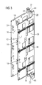
- Fig. 3 is of the multi-phase string fuse module according to the invention, only the two support plates 16 and 42 shown in perspective.
- the right support plate 42 is identical to the support plate 16 is formed.
- the upper and lower rear cross member 38 and 40 can be seen.
- This upper or lower transverse strut 38 or 40 consists of two parts 34 and 44 or 36 and 46, which are designed such that they engage positively in the assembled state of the multi-phase string fuse module.
- stiffening means 48 has. These stiffening means 48 are arranged one above the other on a flat side 50 of the support plate 42.
- a stiffening means 48 a U-profile is provided, whose legs have a plurality of openings.
- the Fig. 4 shows a side view of a populated multi-phase string fuse module according to the invention, wherein the right support plate 42 is removed.
- This side view shows a bus bar package 32 and a string fuse 52 with associated AC contactor 54 of each phase assembly.
- three phase assemblies are arranged one above the other in front on a narrow side of the busbar stack 32.
- This narrow side of the busbar package 32 has a plurality of narrow-side terminals 56 and 58.
- At the terminals 56 is one each Connection of a fuse 52 connected, whereas at the terminal 58, a connection of an AC contactor 54 is connected.
- To each electrically connect a fuse 52 with a narrow-side terminal 56 are in accordance with Fig. 1 Connecting lines 10 provided.
- busbar pieces 60 are used.
- Fig. 1 are a string fuse 2 and an associated AC contactor 4 connected by means of another connecting line 12 with each other electrically in series.
- This further connection line 12 is realized in the multi-phase string fuse module by a busbar piece 62.
- the electrical connection of an AC contactor 4 with an AC outlet 8 is according to the circuit diagram according to Fig. 1 made with a further connecting line 14.
- This connection line 14 is also realized by a busbar piece 64.
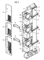
- Fig. 5 is the populated multi-phase string fuse module after Fig. 4 shown in perspective.
- strand fuse 2 according to the circuit diagram in accordance with Fig. 1 two fuses 52 and 66 are provided which are electrically connected in parallel. That is, on the mounting lugs 18 of the support plate 16, the fuses 66 are mechanically fastened, whereas the fuses 52 are mechanically fastened to the mounting lugs 18 of the support plate 42.
- the mounting lugs 20 of the two support plates 16 and 42 are required for mechanical attachment of the AC contactors 54.
- This busbar package 32 has in this illustration, three two-piece devices 68, each consisting of two U-shaped interlocking closure bracket. Each of the two support plates 16 and 42 are detachably connected to this two-piece device 68.
- an upper and lower spacer 70 are provided.
- an upper and a lower coupling element 72 are provided. These coupling elements 72 have a plurality of juxtaposed grooves, which are dimensioned such that the insulating rails of the busbar package 32 can be inserted into this.
- the two coupling elements 72 are each based on the busbars of the busbar package 32, whereby they are fixed in their position. Thus slipping of the busbars within the busbar package 32 is not possible.
- each coupling element 72 has a groove. In this groove, the rear cross member 38 and 40 of the two support plates 16 and 42 extends in the mounted state.
- this multi-phase string fuse module has a plurality of devices 74 which are arranged between current-carrying parts of different potential.
- a plurality of covers 76 are provided, between each of which a stiffening means 78 are arranged. These covers 76 are releasably connected to the front attachment lugs 24 of the support plate 16 and 42. So that the components of the multi-phase string fuse module between the two support plates 16 and 42 can be cooled by means of ambient air (convection cooling), these covers 76 each have a region with perforations.
- a mounted multi-phase string fuse module is shown in perspective.
- This representation can be seen that the stiffeners 48 at the level of the two-piece device 68 of the busbar package 32 on a flat side of the support plate 16 and 42 are arranged.
- the terminals of the AC supply line 6 are located in the upper and lower end faces of the polyphase line protection module.
- the connections of the AC lines 8 are located in a plane parallel to the lower end face of the polyphase line protection module above this end face. This allows an electrical unit to be placed and wired directly to the right of this multi-phase string fuse module.
- the multi-phase string fuse module is particularly narrow due to the structure according to the invention. That in the Fig. 6 shown strand protection module has a width of, for example, 200mm and a height of, for example, 1754mm.
- this multiphase string fuse module consist in a very space-saving arrangement of fuses 2 and 52, 66, shooters 4 and 54 and busbars for larger currents in a housing, this module can be mounted and tested separately. In addition, wear parts (fuses, contactors) can be changed with little effort.
Landscapes
- Engineering & Computer Science (AREA)
- Power Engineering (AREA)
- Fuses (AREA)
- Patch Boards (AREA)
Abstract
Claims (11)
- Module de fusible de ligne à plusieurs phases, comprenant deux plaques ( 16, 42 ) supports et par phase au moins un fusible ( 52, 66 ) de ligne, un contacteur ( 54 ) à courant alternatif, une ligne ( 6 ) d'entrée du courant alternatif et une ligne ( 8 ) de sortie du courant alternatif, dans lequel il est prévu, comme lignes ( 6, 8 ) d'entrée et de sortie, des barres conductrices, qui forment un paquet ( 32 ) de barres conductrices ayant des bornes ( 56, 58 ) du côté frontal et du côté étroit, dans lequel au moins un fusible ( 52, 66 ) de fil et un commutateur ( 54 ) à courant alternatif de l'une de chaque phase sont disposés l'un au-dessus de l'autre dans l'espace, dans lequel ces composants de phase sont disposés l'un au-dessus de l'autre en avant des bornes ( 56, 58 ) du côté étroit du paquet ( 32 ) de barres conductrices entre les deux plaques ( 16, 42 ) supports, qui sont reliées respectivement à un côté plat du paquet ( 32 ) de barres conductrices et sont reliées d'une manière conductrice de l'électricité à ces bornes ( 56, 58 ) du côté étroit, et dans lequel ces composants de phase sont munis du côté avant d'un recouvrement.
- Module de fusible de fil à plusieurs phases suivant la revendication 1, caractérisé en ce que la plaque ( 16, 42 ) support a des talons ( 18, 20 ) de fixation des fusibles ( 52, 66 ) de fil et des contacteurs ( 54 ) à courant alternatif des composants de phase.
- Module de fusible de fil à plusieurs phases suivant la revendication 1 ou 2, caractérisé en ce que la plaque ( 16, 42 ) support a un talon ( 22 ) de fixation vers l'arrière ayant au moins deux trous ( 30 ).
- Module de fusible de fil à plusieurs phases suivant l'une des revendications précédentes, caractérisé en ce que la plaque ( 16, 42 ) support a, du côté avant, un onglet ( 24 ) de fixation ayant des moyens de fixation du recouvrement.
- Module de fusible de fil à plusieurs phases suivant l'une des revendications précédentes, caractérisé en ce que le recouvrement est pourvu de moyens de rigidification.
- Module de fusible de fil à plusieurs phases suivant l'une des revendications précédentes, caractérisé en ce que chaque composant de phase est pourvu du côté avant d'un recouvrement ( 76 ).
- Module de fusible de fil à plusieurs phases suivant la revendication 6, caractérisé en ce qu'un moyen ( 78 ) de raidissement est disposé respectivement entre deux recouvrements ( 76 ).
- Module de fusible de fil à plusieurs phases suivant l'une des revendications précédentes, caractérisé en ce que la plaque ( 16, 42 ) support a plusieurs moyens ( 48 ) de raidissement sur son côté ( 50 ) plat du côté de l'extérieur.
- Module de fusible de fil à plusieurs phases suivant l'une des revendications précédentes, caractérisé en ce que, pour l'immobilisation en position du paquet (32) de barres conductrices entre les deux plaques ( 16, 42 ) supports, il est prévu un élément ( 62 ) de couplage, qui est réalisé, d'une part, en forme de peigne et qui a, d'autre part, une rainure.
- Module de fusible de fil à plusieurs phases suivant l'une des revendications précédentes, caractérisé en ce qu'il est prévu, entre des parties conduisant le courant de potentiel différent, des dispositifs ( 74 ) pour augmenter des espaces d'air et des zones de fuite.
- Module de fusible de fil à plusieurs phases suivant l'une des revendications précédentes, caractérisé en ce que les plaques ( 16, 42 ) supports sont respectivement en métal.
Applications Claiming Priority (2)
| Application Number | Priority Date | Filing Date | Title |
|---|---|---|---|
| DE102006058328A DE102006058328B3 (de) | 2006-12-11 | 2006-12-11 | Mehrphasiges Strangsicherungs-Modul |
| PCT/EP2007/061188 WO2008071492A1 (fr) | 2006-12-11 | 2007-10-19 | Module de fusible de protection de ligne, à phases multiples |
Publications (2)
| Publication Number | Publication Date |
|---|---|
| EP2089945A1 EP2089945A1 (fr) | 2009-08-19 |
| EP2089945B1 true EP2089945B1 (fr) | 2012-07-04 |
Family
ID=38935900
Family Applications (1)
| Application Number | Title | Priority Date | Filing Date |
|---|---|---|---|
| EP07821552A Not-in-force EP2089945B1 (fr) | 2006-12-11 | 2007-10-19 | Module de fusible de protection de ligne, à phases multiples |
Country Status (5)
| Country | Link |
|---|---|
| US (1) | US7924550B2 (fr) |
| EP (1) | EP2089945B1 (fr) |
| CN (1) | CN101553964B (fr) |
| DE (1) | DE102006058328B3 (fr) |
| WO (1) | WO2008071492A1 (fr) |
Families Citing this family (10)
| Publication number | Priority date | Publication date | Assignee | Title |
|---|---|---|---|---|
| DE102006058327B3 (de) * | 2006-12-11 | 2008-05-15 | Siemens Ag | Stromschienenpaket |
| WO2011044624A1 (fr) * | 2009-10-16 | 2011-04-21 | Pace Engineers Group Pty Ltd | Appareil de protection contre le flash d'arc |
| AU2011101542B4 (en) * | 2009-10-16 | 2012-03-01 | Hudson Mckay Group Pty Ltd | Arc flash protection apparatus |
| JP5586241B2 (ja) * | 2010-01-12 | 2014-09-10 | 矢崎総業株式会社 | ヒュージブルリンクユニット |
| DE102010027901A1 (de) | 2010-04-19 | 2011-10-20 | Beckhoff Automation Gmbh | Einspeisemodul |
| US20120038225A1 (en) * | 2010-08-11 | 2012-02-16 | Steven Hunter Grindeland | Vertical Bus Disconnect |
| US10015083B2 (en) | 2011-12-22 | 2018-07-03 | Amazon Technologies, Inc. | Interfaces to manage inter-region connectivity for direct network peerings |
| CN104779529A (zh) * | 2015-03-23 | 2015-07-15 | 国家电网公司 | 一种高强度预制舱式变电站组合结构 |
| CN109890164B (zh) * | 2019-03-18 | 2024-03-26 | 新乡市光明电器有限公司 | 强密封性电气控制盒 |
| DE102020123020A1 (de) | 2020-09-03 | 2022-03-03 | Homag Gmbh | Vorrichtung zur Befestigung und Verdrahtung von elektrischen Einheiten in einem Schaltschrank |
Family Cites Families (12)
| Publication number | Priority date | Publication date | Assignee | Title |
|---|---|---|---|---|
| DE2903322C2 (de) * | 1979-01-29 | 1986-04-30 | Fritz Driescher KG Spezialfabrik für Elektrizitätswerksbedarf GmbH & Co, 5144 Wegberg | Sicherungsschalteinrichtung |
| FR2569061B1 (fr) * | 1984-08-07 | 1987-01-02 | Alsthom Atlantique | Dispositif de distribution electrique a basse tension |
| FR2653607B1 (fr) * | 1989-10-23 | 1992-09-11 | Servelec Ind Sa | Dispositif pour la realisation d'ensembles pour la commande et la protection de circuits electriques basse tension. |
| US5148139A (en) * | 1991-06-28 | 1992-09-15 | Square D Company | Fuse switch unit for panelboards |
| DE9303886U1 (de) * | 1993-03-16 | 1993-06-17 | Siemens Nixdorf Informationssysteme AG, 4790 Paderborn | Stromschienenpaket |
| DE19511350A1 (de) * | 1995-03-28 | 1996-10-02 | Kloeckner Moeller Gmbh | Schienenkanalsystem einer Niederspannungs-Schaltanlage |
| EP0924727B1 (fr) * | 1996-02-28 | 2001-08-08 | Wermelinger AG | Fusible-interrupteur et/ou fusible-sectionneur |
| FR2776465B1 (fr) * | 1998-03-19 | 2000-05-12 | Schneider Electric Ind Sa | Unite fonctionnelle de depart evolutive d'une cellule electrique a basse tension |
| IT1319352B1 (it) * | 2000-12-05 | 2003-10-10 | Abb Ricerca Spa | Quadro elettrico con montaggio semplificato dei componenti del quadro |
| DE10205101B4 (de) * | 2002-02-07 | 2006-04-20 | Siemens Ag | Netzanschlussmodul |
| DE102004013477A1 (de) * | 2004-03-18 | 2005-10-06 | Epcos Ag | Trägerplattform für Leistungselektronik-Bauelemente und Modul mit der Trägerplattform |
| DE102006058327B3 (de) * | 2006-12-11 | 2008-05-15 | Siemens Ag | Stromschienenpaket |
-
2006
- 2006-12-11 DE DE102006058328A patent/DE102006058328B3/de not_active Expired - Fee Related
-
2007
- 2007-10-19 CN CN200780045540XA patent/CN101553964B/zh not_active Expired - Fee Related
- 2007-10-19 WO PCT/EP2007/061188 patent/WO2008071492A1/fr not_active Ceased
- 2007-10-19 EP EP07821552A patent/EP2089945B1/fr not_active Not-in-force
- 2007-10-19 US US12/518,580 patent/US7924550B2/en not_active Expired - Fee Related
Also Published As
| Publication number | Publication date |
|---|---|
| CN101553964A (zh) | 2009-10-07 |
| DE102006058328B3 (de) | 2008-05-08 |
| CN101553964B (zh) | 2012-02-08 |
| WO2008071492A1 (fr) | 2008-06-19 |
| US20100008023A1 (en) | 2010-01-14 |
| US7924550B2 (en) | 2011-04-12 |
| EP2089945A1 (fr) | 2009-08-19 |
Similar Documents
| Publication | Publication Date | Title |
|---|---|---|
| EP2089945B1 (fr) | Module de fusible de protection de ligne, à phases multiples | |
| EP2461440B1 (fr) | Systeme d'enfichage | |
| EP2561531B1 (fr) | Module d'alimentation | |
| EP2143121B1 (fr) | Appareil de commutation d'installation | |
| EP1914838A1 (fr) | Interrupteur d'installation modulaire | |
| EP0872000B1 (fr) | Jeu de barres omnibus pour installation de commutation basse tension | |
| DE102011002874A1 (de) | Konfigurirbare Sicherungsschalttafel mit Berührungsschutz | |
| DE202014009245U1 (de) | Schaltgerät sowie Schaltgeräteanordnung | |
| DE2515152B2 (de) | Elektrische Schaltanlage für Niederspannung | |
| DE4013223C2 (de) | Netzeinspeiseklemme | |
| WO2010052080A2 (fr) | Segment de boîtier pour un point de raccordement de systèmes de barre omnibus | |
| EP2976832A2 (fr) | Onduleur comprenant au moins un pont entre deux barres omnibus | |
| DE8618540U1 (de) | Mehrfach-Steckverbindungseinheit | |
| EP2365506A1 (fr) | Colonne de sécurité et agencement doté d'une telle colonne de sécurité | |
| DE19523592A1 (de) | Niederspannungs-Schaltgeräte-Kombination | |
| WO1999053582A1 (fr) | Installation de commutation a plusieurs zones comportant un ensemble barre omnibus | |
| DE60119830T2 (de) | Rahmenschenkel für ein Rahmengestell, als Leiter zur Verteilung elektrischer Energie | |
| DE10205101B4 (de) | Netzanschlussmodul | |
| WO2009121752A2 (fr) | Dispositif d'utilisation d'un appareil de commutation | |
| DE10260371A1 (de) | Niederspannungs-Leistungsschalter | |
| DE2733895C2 (de) | Einbauvorrichtung zum Einschub eines Bausteins | |
| EP3540752A1 (fr) | Disjoncteur-sectionneur à nh-fusibles | |
| WO2007122109A1 (fr) | Équipement de commutation à moyenne tension à isolation par air | |
| DE202024102099U1 (de) | Sammelschienensystem | |
| CH666376A5 (en) | Drawer inset for modular control appts. - has vertical cable shaft defined by aligned cut=outs in base of each insert |
Legal Events
| Date | Code | Title | Description |
|---|---|---|---|
| PUAI | Public reference made under article 153(3) epc to a published international application that has entered the european phase |
Free format text: ORIGINAL CODE: 0009012 |
|
| 17P | Request for examination filed |
Effective date: 20090514 |
|
| AK | Designated contracting states |
Kind code of ref document: A1 Designated state(s): AT BE BG CH CY CZ DE DK EE ES FI FR GB GR HU IE IS IT LI LT LU LV MC MT NL PL PT RO SE SI SK TR |
|
| DAX | Request for extension of the european patent (deleted) | ||
| GRAP | Despatch of communication of intention to grant a patent |
Free format text: ORIGINAL CODE: EPIDOSNIGR1 |
|
| GRAS | Grant fee paid |
Free format text: ORIGINAL CODE: EPIDOSNIGR3 |
|
| GRAA | (expected) grant |
Free format text: ORIGINAL CODE: 0009210 |
|
| AK | Designated contracting states |
Kind code of ref document: B1 Designated state(s): AT BE BG CH CY CZ DE DK EE ES FI FR GB GR HU IE IS IT LI LT LU LV MC MT NL PL PT RO SE SI SK TR |
|
| REG | Reference to a national code |
Ref country code: GB Ref legal event code: FG4D Free format text: NOT ENGLISH |
|
| REG | Reference to a national code |
Ref country code: CH Ref legal event code: EP |
|
| REG | Reference to a national code |
Ref country code: AT Ref legal event code: REF Ref document number: 565466 Country of ref document: AT Kind code of ref document: T Effective date: 20120715 |
|
| REG | Reference to a national code |
Ref country code: IE Ref legal event code: FG4D Free format text: LANGUAGE OF EP DOCUMENT: GERMAN |
|
| REG | Reference to a national code |
Ref country code: DE Ref legal event code: R096 Ref document number: 502007010166 Country of ref document: DE Effective date: 20120830 |
|
| REG | Reference to a national code |
Ref country code: NL Ref legal event code: VDEP Effective date: 20120704 |
|
| PG25 | Lapsed in a contracting state [announced via postgrant information from national office to epo] |
Ref country code: SI Free format text: LAPSE BECAUSE OF FAILURE TO SUBMIT A TRANSLATION OF THE DESCRIPTION OR TO PAY THE FEE WITHIN THE PRESCRIBED TIME-LIMIT Effective date: 20120704 |
|
| REG | Reference to a national code |
Ref country code: LT Ref legal event code: MG4D Effective date: 20120711 |
|
| PG25 | Lapsed in a contracting state [announced via postgrant information from national office to epo] |
Ref country code: LT Free format text: LAPSE BECAUSE OF FAILURE TO SUBMIT A TRANSLATION OF THE DESCRIPTION OR TO PAY THE FEE WITHIN THE PRESCRIBED TIME-LIMIT Effective date: 20120704 Ref country code: CY Free format text: LAPSE BECAUSE OF FAILURE TO SUBMIT A TRANSLATION OF THE DESCRIPTION OR TO PAY THE FEE WITHIN THE PRESCRIBED TIME-LIMIT Effective date: 20120704 Ref country code: IS Free format text: LAPSE BECAUSE OF FAILURE TO SUBMIT A TRANSLATION OF THE DESCRIPTION OR TO PAY THE FEE WITHIN THE PRESCRIBED TIME-LIMIT Effective date: 20121104 Ref country code: FI Free format text: LAPSE BECAUSE OF FAILURE TO SUBMIT A TRANSLATION OF THE DESCRIPTION OR TO PAY THE FEE WITHIN THE PRESCRIBED TIME-LIMIT Effective date: 20120704 |
|
| PG25 | Lapsed in a contracting state [announced via postgrant information from national office to epo] |
Ref country code: LV Free format text: LAPSE BECAUSE OF FAILURE TO SUBMIT A TRANSLATION OF THE DESCRIPTION OR TO PAY THE FEE WITHIN THE PRESCRIBED TIME-LIMIT Effective date: 20120704 Ref country code: GR Free format text: LAPSE BECAUSE OF FAILURE TO SUBMIT A TRANSLATION OF THE DESCRIPTION OR TO PAY THE FEE WITHIN THE PRESCRIBED TIME-LIMIT Effective date: 20121005 Ref country code: SE Free format text: LAPSE BECAUSE OF FAILURE TO SUBMIT A TRANSLATION OF THE DESCRIPTION OR TO PAY THE FEE WITHIN THE PRESCRIBED TIME-LIMIT Effective date: 20120704 Ref country code: PL Free format text: LAPSE BECAUSE OF FAILURE TO SUBMIT A TRANSLATION OF THE DESCRIPTION OR TO PAY THE FEE WITHIN THE PRESCRIBED TIME-LIMIT Effective date: 20120704 Ref country code: PT Free format text: LAPSE BECAUSE OF FAILURE TO SUBMIT A TRANSLATION OF THE DESCRIPTION OR TO PAY THE FEE WITHIN THE PRESCRIBED TIME-LIMIT Effective date: 20121105 |
|
| RAP2 | Party data changed (patent owner data changed or rights of a patent transferred) |
Owner name: SIEMENS AKTIENGESELLSCHAFT |
|
| PG25 | Lapsed in a contracting state [announced via postgrant information from national office to epo] |
Ref country code: NL Free format text: LAPSE BECAUSE OF FAILURE TO SUBMIT A TRANSLATION OF THE DESCRIPTION OR TO PAY THE FEE WITHIN THE PRESCRIBED TIME-LIMIT Effective date: 20120704 |
|
| BERE | Be: lapsed |
Owner name: SIEMENS A.G. Effective date: 20121031 |
|
| PG25 | Lapsed in a contracting state [announced via postgrant information from national office to epo] |
Ref country code: CZ Free format text: LAPSE BECAUSE OF FAILURE TO SUBMIT A TRANSLATION OF THE DESCRIPTION OR TO PAY THE FEE WITHIN THE PRESCRIBED TIME-LIMIT Effective date: 20120704 Ref country code: RO Free format text: LAPSE BECAUSE OF FAILURE TO SUBMIT A TRANSLATION OF THE DESCRIPTION OR TO PAY THE FEE WITHIN THE PRESCRIBED TIME-LIMIT Effective date: 20120704 Ref country code: EE Free format text: LAPSE BECAUSE OF FAILURE TO SUBMIT A TRANSLATION OF THE DESCRIPTION OR TO PAY THE FEE WITHIN THE PRESCRIBED TIME-LIMIT Effective date: 20120704 Ref country code: ES Free format text: LAPSE BECAUSE OF FAILURE TO SUBMIT A TRANSLATION OF THE DESCRIPTION OR TO PAY THE FEE WITHIN THE PRESCRIBED TIME-LIMIT Effective date: 20121015 Ref country code: DK Free format text: LAPSE BECAUSE OF FAILURE TO SUBMIT A TRANSLATION OF THE DESCRIPTION OR TO PAY THE FEE WITHIN THE PRESCRIBED TIME-LIMIT Effective date: 20120704 |
|
| PLBE | No opposition filed within time limit |
Free format text: ORIGINAL CODE: 0009261 |
|
| STAA | Information on the status of an ep patent application or granted ep patent |
Free format text: STATUS: NO OPPOSITION FILED WITHIN TIME LIMIT |
|
| PG25 | Lapsed in a contracting state [announced via postgrant information from national office to epo] |
Ref country code: SK Free format text: LAPSE BECAUSE OF FAILURE TO SUBMIT A TRANSLATION OF THE DESCRIPTION OR TO PAY THE FEE WITHIN THE PRESCRIBED TIME-LIMIT Effective date: 20120704 Ref country code: MC Free format text: LAPSE BECAUSE OF NON-PAYMENT OF DUE FEES Effective date: 20121031 Ref country code: IT Free format text: LAPSE BECAUSE OF FAILURE TO SUBMIT A TRANSLATION OF THE DESCRIPTION OR TO PAY THE FEE WITHIN THE PRESCRIBED TIME-LIMIT Effective date: 20120704 |
|
| REG | Reference to a national code |
Ref country code: CH Ref legal event code: PL |
|
| 26N | No opposition filed |
Effective date: 20130405 |
|
| REG | Reference to a national code |
Ref country code: IE Ref legal event code: MM4A |
|
| PG25 | Lapsed in a contracting state [announced via postgrant information from national office to epo] |
Ref country code: BE Free format text: LAPSE BECAUSE OF NON-PAYMENT OF DUE FEES Effective date: 20121031 Ref country code: CH Free format text: LAPSE BECAUSE OF NON-PAYMENT OF DUE FEES Effective date: 20121031 Ref country code: LI Free format text: LAPSE BECAUSE OF NON-PAYMENT OF DUE FEES Effective date: 20121031 Ref country code: IE Free format text: LAPSE BECAUSE OF NON-PAYMENT OF DUE FEES Effective date: 20121019 Ref country code: BG Free format text: LAPSE BECAUSE OF FAILURE TO SUBMIT A TRANSLATION OF THE DESCRIPTION OR TO PAY THE FEE WITHIN THE PRESCRIBED TIME-LIMIT Effective date: 20121004 |
|
| REG | Reference to a national code |
Ref country code: DE Ref legal event code: R097 Ref document number: 502007010166 Country of ref document: DE Effective date: 20130405 |
|
| PG25 | Lapsed in a contracting state [announced via postgrant information from national office to epo] |
Ref country code: MT Free format text: LAPSE BECAUSE OF FAILURE TO SUBMIT A TRANSLATION OF THE DESCRIPTION OR TO PAY THE FEE WITHIN THE PRESCRIBED TIME-LIMIT Effective date: 20120704 |
|
| REG | Reference to a national code |
Ref country code: AT Ref legal event code: MM01 Ref document number: 565466 Country of ref document: AT Kind code of ref document: T Effective date: 20121031 |
|
| PG25 | Lapsed in a contracting state [announced via postgrant information from national office to epo] |
Ref country code: AT Free format text: LAPSE BECAUSE OF NON-PAYMENT OF DUE FEES Effective date: 20121031 |
|
| PG25 | Lapsed in a contracting state [announced via postgrant information from national office to epo] |
Ref country code: TR Free format text: LAPSE BECAUSE OF FAILURE TO SUBMIT A TRANSLATION OF THE DESCRIPTION OR TO PAY THE FEE WITHIN THE PRESCRIBED TIME-LIMIT Effective date: 20120704 |
|
| PG25 | Lapsed in a contracting state [announced via postgrant information from national office to epo] |
Ref country code: LU Free format text: LAPSE BECAUSE OF NON-PAYMENT OF DUE FEES Effective date: 20121019 |
|
| PG25 | Lapsed in a contracting state [announced via postgrant information from national office to epo] |
Ref country code: HU Free format text: LAPSE BECAUSE OF FAILURE TO SUBMIT A TRANSLATION OF THE DESCRIPTION OR TO PAY THE FEE WITHIN THE PRESCRIBED TIME-LIMIT Effective date: 20071019 |
|
| REG | Reference to a national code |
Ref country code: FR Ref legal event code: PLFP Year of fee payment: 9 |
|
| REG | Reference to a national code |
Ref country code: FR Ref legal event code: PLFP Year of fee payment: 10 |
|
| REG | Reference to a national code |
Ref country code: FR Ref legal event code: PLFP Year of fee payment: 11 |
|
| REG | Reference to a national code |
Ref country code: FR Ref legal event code: PLFP Year of fee payment: 12 |
|
| PGFP | Annual fee paid to national office [announced via postgrant information from national office to epo] |
Ref country code: DE Payment date: 20181217 Year of fee payment: 12 |
|
| PGFP | Annual fee paid to national office [announced via postgrant information from national office to epo] |
Ref country code: GB Payment date: 20181005 Year of fee payment: 12 Ref country code: FR Payment date: 20181018 Year of fee payment: 12 |
|
| REG | Reference to a national code |
Ref country code: DE Ref legal event code: R119 Ref document number: 502007010166 Country of ref document: DE |
|
| PG25 | Lapsed in a contracting state [announced via postgrant information from national office to epo] |
Ref country code: DE Free format text: LAPSE BECAUSE OF NON-PAYMENT OF DUE FEES Effective date: 20200501 |
|
| GBPC | Gb: european patent ceased through non-payment of renewal fee |
Effective date: 20191019 |
|
| PG25 | Lapsed in a contracting state [announced via postgrant information from national office to epo] |
Ref country code: GB Free format text: LAPSE BECAUSE OF NON-PAYMENT OF DUE FEES Effective date: 20191019 Ref country code: FR Free format text: LAPSE BECAUSE OF NON-PAYMENT OF DUE FEES Effective date: 20191031 |