EP2090380A1 - Dispositif de poudrage ou de saupoudrage de matières d'impression - Google Patents
Dispositif de poudrage ou de saupoudrage de matières d'impression Download PDFInfo
- Publication number
- EP2090380A1 EP2090380A1 EP09151488A EP09151488A EP2090380A1 EP 2090380 A1 EP2090380 A1 EP 2090380A1 EP 09151488 A EP09151488 A EP 09151488A EP 09151488 A EP09151488 A EP 09151488A EP 2090380 A1 EP2090380 A1 EP 2090380A1
- Authority
- EP
- European Patent Office
- Prior art keywords
- cyclone
- powder particles
- wheel
- relatively
- powder
- Prior art date
- Legal status (The legal status is an assumption and is not a legal conclusion. Google has not performed a legal analysis and makes no representation as to the accuracy of the status listed.)
- Withdrawn
Links
- 238000000227 grinding Methods 0.000 title claims description 10
- 238000010410 dusting Methods 0.000 title claims description 7
- 239000000463 material Substances 0.000 title description 6
- 239000002245 particle Substances 0.000 claims abstract description 60
- 239000000843 powder Substances 0.000 claims description 60
- 239000000758 substrate Substances 0.000 claims description 20
- 239000000203 mixture Substances 0.000 claims description 13
- 230000002093 peripheral effect Effects 0.000 claims description 7
- 239000000428 dust Substances 0.000 description 4
- 238000005054 agglomeration Methods 0.000 description 2
- 230000002776 aggregation Effects 0.000 description 2
- 230000006735 deficit Effects 0.000 description 2
- 230000005611 electricity Effects 0.000 description 2
- 238000000926 separation method Methods 0.000 description 2
- 241000792859 Enema Species 0.000 description 1
- 230000000903 blocking effect Effects 0.000 description 1
- 238000011109 contamination Methods 0.000 description 1
- 230000001419 dependent effect Effects 0.000 description 1
- 238000009795 derivation Methods 0.000 description 1
- 238000001035 drying Methods 0.000 description 1
- 239000007920 enema Substances 0.000 description 1
- 229940095399 enema Drugs 0.000 description 1
- 238000005516 engineering process Methods 0.000 description 1
- 238000000034 method Methods 0.000 description 1
- 230000010152 pollination Effects 0.000 description 1
Images

Classifications
-
- B—PERFORMING OPERATIONS; TRANSPORTING
- B07—SEPARATING SOLIDS FROM SOLIDS; SORTING
- B07B—SEPARATING SOLIDS FROM SOLIDS BY SIEVING, SCREENING, SIFTING OR BY USING GAS CURRENTS; SEPARATING BY OTHER DRY METHODS APPLICABLE TO BULK MATERIAL, e.g. LOOSE ARTICLES FIT TO BE HANDLED LIKE BULK MATERIAL
- B07B7/00—Selective separation of solid materials carried by, or dispersed in, gas currents
- B07B7/08—Selective separation of solid materials carried by, or dispersed in, gas currents using centrifugal force
- B07B7/083—Selective separation of solid materials carried by, or dispersed in, gas currents using centrifugal force generated by rotating vanes, discs, drums, or brushes
-
- B—PERFORMING OPERATIONS; TRANSPORTING
- B41—PRINTING; LINING MACHINES; TYPEWRITERS; STAMPS
- B41F—PRINTING MACHINES OR PRESSES
- B41F23/00—Devices for treating the surfaces of sheets, webs, or other articles in connection with printing
- B41F23/04—Devices for treating the surfaces of sheets, webs, or other articles in connection with printing by heat drying, by cooling, by applying powders
- B41F23/06—Powdering devices, e.g. for preventing set-off
Definitions
- the invention relates to a device for powdering or dusting substrates according to the preamble of claim 1.
- the powdering or pollination of printed printed sheets serves to prevent blocking of the printed sheets in the area of the delivery arm. Furthermore, the powder applied to the printing sheets can facilitate the drying of the applied printing ink.
- the powder particles which are thrown onto the printing substrate with a cyclone or the powder particles which are directed onto the printing material by means of a powder-air mixture comprise powder particles of different sizes, but only those powder particles are to be directed onto the printing material, which in terms of their size or their weight are above a threshold. Too small or too light powder particles tend namely to spread undefined after leaving the Bepud réelles owned and before reaching the substrate in the environment of the sheet-fed press, whereby the sheet-fed press can pollute.
- the present invention based on the problem of creating a novel device and a novel method for powdering or dusting of substrates.
- a classifier wheel is positioned in the cyclone which rotates relative to the fixed cyclone such that relatively large or relatively heavy powder particles are moved radially outward against a wall of the cyclone so that they leave the cyclone in the continuous stream of powder particles and on the Are relatively small or relatively light powder particles are moved radially inward in a cavity enclosed by the sorterrad so that they do not leave the cyclone in the continuous stream of powder particles.
- a separator wheel is positioned within the stationary cyclone.
- the classifier wheel which rotates relative to the fixed cyclone, allows effective separation between the relatively large and relatively heavy powder particles which are to leave the cyclone and be directed onto the substrate from the relatively small or relatively light powder particles containing the cyclone should not leave. This makes it possible to effectively avoid contamination of the printing machine as well as health impairments for persons working on the printing machine.
- Fig. 1 shows a schematic representation of a device according to the invention for powdering or dusting of substrates, wherein the device comprises a trained as a cyclone 10 powdering module.
- the cyclone 10 is a fixed, cylindrical container to which a continuous stream of a powder-air mixture 12 is supplied via a feed line 11, wherein the powder-air mixture 12 into the cyclone 10 with an inlet velocity V Z, An entrance. From the cyclone 10 exits a continuous stream 13 of powder particles 14, wherein the powder particles 14 are thrown from the cyclone 10 in the direction of a substrate to be powdered 15. The powder particles 14 leave the cyclone 10 at a defined exit velocity V Z, AUS .
- a classifying wheel 16 is positioned in the cyclone 10.
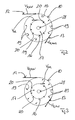
- the cyclone 10 surrounds according to Fig. 2, 3rd the preparerrad 16 preferably concentric.
- the classifier wheel 16 rotates relative to the stationary cyclone 10, the classifier wheel 16 having a peripheral speed V SR .
- the powder particles entering the cyclone 10 stream from the powder-air mixture 12 are moved depending on their size or their weight either radially outward against a cylindrical wall of the cyclone 10 or radially inwardly into a space enclosed by the reformerrad 16 cavity 17th , wherein for this purpose 16 slots 18 are introduced into a wall of the classifier wheel.
- Relatively large or relatively heavy powder particles are in the direction of arrows 19 radially outward moved against the wall of the cyclone 10 so that they leave the cyclone 10 in the continuous stream 13 of powder particles 14 and can be directed to the substrate 15.
- relatively small or relatively light powder particles are moved radially inward in the cavity 17 enclosed by the separator wheel 16 in the direction of the arrows 20, so that they do not leave the cyclone 10 in the continuous stream 13 of powder particles 14.
- the limit value between the relatively large or relatively heavy powder particles which are to be directed onto the printing material 15 and the relatively small or relatively light powder particles which are not intended to be directed onto the printing material 15 can be determined by a relative speed between the entry speed V Z , A of the powder-air mixture 12 in the cyclone and the peripheral speed V SR of reformerrads 16 or by a relative speed between the exit velocity V Z, AUS of the powder particles 13 from the cyclone 10 and the peripheral speed V SR of detoxerrads 16 are determined. Furthermore, this limit value depends on the difference between the radius of the cyclone 10 and the radius of the separator wheel 16.
- the cyclone 10 is supplied with a continuous flow 12 of a powder-air mixture via the supply line 11, wherein the supply line 11 opens into the cyclone 10 via an inlet 21.
- the powder-air mixture 12 is provided by mixing in a metering unit or mixing unit 22 an air stream 25 provided by a fan 23 and a valve 24 with powder particles 26 of a powder supply 27.
- relatively small or relatively light powder particles which enter the cavity 17 of the separator wheel 16 can be removed with the aid of a dip tube 28 from the classifier wheel 16 and thus from the cyclone 10.
- a stream 29 of relatively small or light powder particles is fed to a cyclone 30, in which the relatively small or relatively light powder particles are separated from the air and collected in a dust bunker 31. Via rotary valves 32, the dust bunker 31 can be emptied during operation.
- An air stream 33 separated from the relatively small or relatively light powder particles in the cyclone 30 can be removed by means of a blower 34 and a valve 35 as well as a discharge line 36.
- the supply line 11 opens for the powder-air mixture 12 in the cyclone 10 in an inlet 21, wherein the inlet 21 can be designed tangentially or spirally or helically.
- the inlet height of the inlet 21 is at least 1.5 times as large as the inlet width of the inlet 21st
- the relatively heavy or relatively large powder particles are, as already mentioned, pressed radially outward against the wall of the cyclone 10, wherein the wall of the cyclone 10 is preferably carried out hydraulically smooth.
- the wall of the cyclone 10 can also be provided with spiral grooves, or have so-called baffles, which ensure that an agglomeration of powder particles is reduced.
- a secondary air inlet may be integrated into the wall of the cyclone 10, which additionally prevents agglomeration of powder particles.
- Radially inside, the wall of the cyclone 10 is preferably made of a material that promotes electrostatic or triboelectric charging of the powder particles on the wall of the cyclone 10.
- the reformerrad 16 is connected to a ground potential 37 and therefore grounded.
- Relatively large or relatively heavy powder particles 14 are thrown onto the printing substrate 15 with the aid of the cyclone 10, the cyclone 10 having a nozzle-like outlet 38 through which the relatively large or relatively heavy, electrostatically charged powder particles 14 leave the cyclone 10.
- the nozzle-like outlet 38 is preferably round or oval or slot-shaped and arranged parallel to the axis of the separator wheel 16.
- a nozzle width of the nozzle-like outlet 38 corresponds at most to the inlet height of the inlet 21.
- the nozzle-like outlet 38 have a nozzle guide 39, the maximum reaches up to an outer radius of the separator wheel 16 and is directed in the direction of the substrate 15 to be gepauternden.
- the classifier wheel 16 is positioned centrally in the cyclone 10.
- an eccentric arrangement of the crusherrads 16 in the cyclone 10 is possible.
- the exit velocity V Z, OUT of the powder particles 13 from the cyclone 10 corresponds at most to the entrance velocity V Z, EIN of the flow from the powder-air mixture 12 into the cyclone 10. Since the powder particles are braked on the wall of the cyclone 10, the Exit velocity V Z, OFF typically less than the entrance velocity V Z, ON .
- Fig. 2 is the peripheral speed V SR of reformerrads 16 opposite to the entrance velocity V Z, A directed.
Landscapes
- Engineering & Computer Science (AREA)
- Mechanical Engineering (AREA)
- Cyclones (AREA)
Applications Claiming Priority (1)
| Application Number | Priority Date | Filing Date | Title |
|---|---|---|---|
| DE200810009289 DE102008009289A1 (de) | 2008-02-15 | 2008-02-15 | Vorrichtung zum Bepudern bzw. Bestäuben von Bedruckstoffen |
Publications (1)
| Publication Number | Publication Date |
|---|---|
| EP2090380A1 true EP2090380A1 (fr) | 2009-08-19 |
Family
ID=40619537
Family Applications (1)
| Application Number | Title | Priority Date | Filing Date |
|---|---|---|---|
| EP09151488A Withdrawn EP2090380A1 (fr) | 2008-02-15 | 2009-01-28 | Dispositif de poudrage ou de saupoudrage de matières d'impression |
Country Status (2)
| Country | Link |
|---|---|
| EP (1) | EP2090380A1 (fr) |
| DE (1) | DE102008009289A1 (fr) |
Citations (6)
| Publication number | Priority date | Publication date | Assignee | Title |
|---|---|---|---|---|
| FR2460725A1 (fr) * | 1979-07-02 | 1981-01-30 | Kawasaki Heavy Ind Ltd | Appareil de separation a air pour separer des materiaux constitues de petites particules de materiaux constitues de grosses particules en utilisant un courant d'air |
| US4257880A (en) * | 1979-06-28 | 1981-03-24 | Jones Donald W | Centrifugal air classifying apparatus |
| EP0468426A2 (fr) * | 1990-07-23 | 1992-01-29 | Kubota Corporation | Séparateur pour des matières poudreuses |
| US20040238415A1 (en) * | 2003-05-29 | 2004-12-02 | Alstom (Switzerland) Ltd | High efficiency two-stage dynamic classifier |
| DE102005019363A1 (de) | 2005-04-26 | 2006-11-02 | Man Roland Druckmaschinen Ag | Vorrichtung und Verfahren zum Bepudern bzw. Bestäuben von Bedruckstoffen |
| EP1787724A2 (fr) * | 2005-11-18 | 2007-05-23 | MAN Roland Druckmaschinen AG | Dispositif et processus de poudrage ou saupoudrage d'un substrat d'impression |
-
2008
- 2008-02-15 DE DE200810009289 patent/DE102008009289A1/de not_active Withdrawn
-
2009
- 2009-01-28 EP EP09151488A patent/EP2090380A1/fr not_active Withdrawn
Patent Citations (7)
| Publication number | Priority date | Publication date | Assignee | Title |
|---|---|---|---|---|
| US4257880A (en) * | 1979-06-28 | 1981-03-24 | Jones Donald W | Centrifugal air classifying apparatus |
| FR2460725A1 (fr) * | 1979-07-02 | 1981-01-30 | Kawasaki Heavy Ind Ltd | Appareil de separation a air pour separer des materiaux constitues de petites particules de materiaux constitues de grosses particules en utilisant un courant d'air |
| EP0468426A2 (fr) * | 1990-07-23 | 1992-01-29 | Kubota Corporation | Séparateur pour des matières poudreuses |
| US20040238415A1 (en) * | 2003-05-29 | 2004-12-02 | Alstom (Switzerland) Ltd | High efficiency two-stage dynamic classifier |
| DE102005019363A1 (de) | 2005-04-26 | 2006-11-02 | Man Roland Druckmaschinen Ag | Vorrichtung und Verfahren zum Bepudern bzw. Bestäuben von Bedruckstoffen |
| EP1787724A2 (fr) * | 2005-11-18 | 2007-05-23 | MAN Roland Druckmaschinen AG | Dispositif et processus de poudrage ou saupoudrage d'un substrat d'impression |
| DE102005055111A1 (de) | 2005-11-18 | 2007-05-24 | Man Roland Druckmaschinen Ag | Vorrichtung und Verfahren zum Bepudern bzw. Bestäuben von Bedruckstoffen |
Also Published As
| Publication number | Publication date |
|---|---|
| DE102008009289A1 (de) | 2009-08-20 |
Similar Documents
| Publication | Publication Date | Title |
|---|---|---|
| DE112011105175B4 (de) | Filter | |
| EP3274112B1 (fr) | Dispositif de refroidissement de sable de moulage | |
| EP2671647A1 (fr) | Dispositif de séparation de brouillard de peinture | |
| EP0638365B1 (fr) | Procédé et dispositif pour séparer des matières solides à grains fins en deux fractions granulométriques | |
| EP0199003A2 (fr) | Trieur à air rotatif avec cage centrifuge | |
| EP1080786A1 (fr) | Procédé, dispositif et système pour broyeur à jet à lit fluidisé | |
| EP3268109B1 (fr) | Dispositif de séparation pour la séparation de particules | |
| DE3222878C1 (de) | Verfahren zum Betreiben eines Windsichters und Windsichter zur Durchfuehrung des Verfahrens | |
| DE3038625A1 (de) | Drehluft-fliehkraft-streusichter | |
| DE1407950A1 (de) | Verfahren zum Abscheiden von spezifisch schwereren Teilchen aus stroemenden Medien | |
| DE3638915A1 (de) | Zentrifugalwindsichter | |
| DE1482454B1 (de) | Umluftsichter | |
| EP2800619B1 (fr) | Séparateur du type cyclone, en particulier pour la gestion des déchets | |
| DE2461793A1 (de) | Verfahren und vorrichtung zur sichtung von mahlgut aus der prallzerkleinerung koerniger produkte | |
| EP2090380A1 (fr) | Dispositif de poudrage ou de saupoudrage de matières d'impression | |
| DE2220534B2 (de) | Drehströmungswirbler zur Sichtung und Abscheidung feinkörniger Partikel | |
| DE1607642A1 (de) | Verfahren und Vorrichtung zum Abtrennen einer Grobfraktion aus einem pneumatisch gefoerderten Schuettgutstrom | |
| DE2401255A1 (de) | Dispergiereinrichtung fuer streuwindsichter | |
| DE2629745C2 (de) | Spiralwindsichter | |
| EP2251099B2 (fr) | Dispositif de séparation d'un matériau en produits fins et produits grossiers | |
| EP0602557A1 (fr) | Appareil d'alimentation | |
| DE102008029737B4 (de) | Vorrichtung und Verfahren zum Klassieren von Feststoffen sowie Aufbereitungssystem | |
| EP0038794B1 (fr) | Installation de broyage | |
| DE829850C (de) | Sichter | |
| EP1787724A2 (fr) | Dispositif et processus de poudrage ou saupoudrage d'un substrat d'impression |
Legal Events
| Date | Code | Title | Description |
|---|---|---|---|
| PUAI | Public reference made under article 153(3) epc to a published international application that has entered the european phase |
Free format text: ORIGINAL CODE: 0009012 |
|
| AK | Designated contracting states |
Kind code of ref document: A1 Designated state(s): AT BE BG CH CY CZ DE DK EE ES FI FR GB GR HR HU IE IS IT LI LT LU LV MC MK MT NL NO PL PT RO SE SI SK TR |
|
| AX | Request for extension of the european patent |
Extension state: AL BA RS |
|
| 17P | Request for examination filed |
Effective date: 20100219 |
|
| 17Q | First examination report despatched |
Effective date: 20100318 |
|
| AKX | Designation fees paid |
Designated state(s): AT BE BG CH CY CZ DE DK EE ES FI FR GB GR HR HU IE IS IT LI LT LU LV MC MK MT NL NO PL PT RO SE SI SK TR |
|
| 19U | Interruption of proceedings before grant |
Effective date: 20120201 |
|
| 19W | Proceedings resumed before grant after interruption of proceedings |
Effective date: 20140203 |
|
| STAA | Information on the status of an ep patent application or granted ep patent |
Free format text: STATUS: THE APPLICATION HAS BEEN WITHDRAWN |
|
| 18W | Application withdrawn |
Effective date: 20140311 |