EP3268109B1 - Dispositif de séparation pour la séparation de particules - Google Patents
Dispositif de séparation pour la séparation de particules Download PDFInfo
- Publication number
- EP3268109B1 EP3268109B1 EP16703133.5A EP16703133A EP3268109B1 EP 3268109 B1 EP3268109 B1 EP 3268109B1 EP 16703133 A EP16703133 A EP 16703133A EP 3268109 B1 EP3268109 B1 EP 3268109B1
- Authority
- EP
- European Patent Office
- Prior art keywords
- separating
- separation
- particles
- separator
- gas stream
- Prior art date
- Legal status (The legal status is an assumption and is not a legal conclusion. Google has not performed a legal analysis and makes no representation as to the accuracy of the status listed.)
- Active
Links
Images


Classifications
-
- B—PERFORMING OPERATIONS; TRANSPORTING
- B01—PHYSICAL OR CHEMICAL PROCESSES OR APPARATUS IN GENERAL
- B01D—SEPARATION
- B01D50/00—Combinations of methods or devices for separating particles from gases or vapours
- B01D50/20—Combinations of devices covered by groups B01D45/00 and B01D46/00
-
- B—PERFORMING OPERATIONS; TRANSPORTING
- B01—PHYSICAL OR CHEMICAL PROCESSES OR APPARATUS IN GENERAL
- B01D—SEPARATION
- B01D45/00—Separating dispersed particles from gases or vapours by gravity, inertia, or centrifugal forces
- B01D45/04—Separating dispersed particles from gases or vapours by gravity, inertia, or centrifugal forces by utilising inertia
- B01D45/08—Separating dispersed particles from gases or vapours by gravity, inertia, or centrifugal forces by utilising inertia by impingement against baffle separators
-
- B—PERFORMING OPERATIONS; TRANSPORTING
- B01—PHYSICAL OR CHEMICAL PROCESSES OR APPARATUS IN GENERAL
- B01D—SEPARATION
- B01D46/00—Filters or filtering processes specially modified for separating dispersed particles from gases or vapours
- B01D46/02—Particle separators, e.g. dust precipitators, having hollow filters made of flexible material
- B01D46/06—Particle separators, e.g. dust precipitators, having hollow filters made of flexible material with means keeping the working surfaces flat
- B01D46/08—Particle separators, e.g. dust precipitators, having hollow filters made of flexible material with means keeping the working surfaces flat the working surfaces forming a star shape
-
- B—PERFORMING OPERATIONS; TRANSPORTING
- B05—SPRAYING OR ATOMISING IN GENERAL; APPLYING FLUENT MATERIALS TO SURFACES, IN GENERAL
- B05B—SPRAYING APPARATUS; ATOMISING APPARATUS; NOZZLES
- B05B14/00—Arrangements for collecting, re-using or eliminating excess spraying material
- B05B14/40—Arrangements for collecting, re-using or eliminating excess spraying material for use in spray booths
- B05B14/43—Arrangements for collecting, re-using or eliminating excess spraying material for use in spray booths by filtering the air charged with excess material
-
- B—PERFORMING OPERATIONS; TRANSPORTING
- B05—SPRAYING OR ATOMISING IN GENERAL; APPLYING FLUENT MATERIALS TO SURFACES, IN GENERAL
- B05B—SPRAYING APPARATUS; ATOMISING APPARATUS; NOZZLES
- B05B16/00—Spray booths
- B05B16/60—Ventilation arrangements specially adapted therefor
-
- Y—GENERAL TAGGING OF NEW TECHNOLOGICAL DEVELOPMENTS; GENERAL TAGGING OF CROSS-SECTIONAL TECHNOLOGIES SPANNING OVER SEVERAL SECTIONS OF THE IPC; TECHNICAL SUBJECTS COVERED BY FORMER USPC CROSS-REFERENCE ART COLLECTIONS [XRACs] AND DIGESTS
- Y02—TECHNOLOGIES OR APPLICATIONS FOR MITIGATION OR ADAPTATION AGAINST CLIMATE CHANGE
- Y02P—CLIMATE CHANGE MITIGATION TECHNOLOGIES IN THE PRODUCTION OR PROCESSING OF GOODS
- Y02P70/00—Climate change mitigation technologies in the production process for final industrial or consumer products
- Y02P70/10—Greenhouse gas [GHG] capture, material saving, heat recovery or other energy efficient measures, e.g. motor control, characterised by manufacturing processes, e.g. for rolling metal or metal working
Definitions
- the present invention relates to a separation device for separating particles from a raw gas flow, a proportion of solid, liquid and / or pasty particles being carried along in the raw gas flow.
- the raw gas flow passes through the separation device in a main flow direction and has a main separator which separates at least some of the particles from the raw gas flow, the raw gas flow flowing through the main separator in the main flow direction and exiting the main separator as a clean gas flow.
- a separation device for separating particles is for example from the DE102007040901A1 known and has as the main separator a filter device for separating wet paint overspray from a raw gas stream containing overspray particles.
- the filter device comprises a filter element for separating the overspray from the raw gas flow. The raw gas flow flows through the filter element in a main flow direction and emerges from the filter device as a clean gas flow.
- a separation device for separating particles is also from the EP0875275A1 and from the WO2015 / 090942A1 known and has a multi-stage separation device with a pre-separator and a main separator, wherein the pre-separator comprises a plurality of rotatable separating elements with bristles, and wherein the bristles of adjacent separating elements are in contact.
- the present invention is based on the object of providing a separating device whose main separator has a long service life. Such a separation device should also be able to be operated inexpensively by regeneration during operation.
- a generic separation device for separating particles from a raw gas stream which one Pre-separator for separating at least a part of the particles from the raw gas flow, which is arranged upstream of the main separator in such a way that the raw gas flow in the main flow direction first flows through the pre-separator and then through the main separator.
- the pre-separator comprises a separator element which is provided for deflecting the raw gas flow, the separator element comprising a shaft and a radial surface element which is arranged on the shaft protruding radially from the shaft and which has a separation surface arranged on the radial surface element from which particles the raw gas stream can be deposited.
- the outer contour of a separating element is preferably the surface of a fictitious approximately cylindrical and / or prism-shaped body.
- a separating element is designed to be rotatable continuously or at intervals about an axis of rotation in order to adjust the separating element between several working positions.
- the separation element has at least two separation surfaces for separating particles, with one separation surface of the separation element being in a separation position in a first working position of the separation element, while at the same time another separation surface of the same separation element is in a regeneration position.
- a separation surface of the separation element acts as a flow guide element that protrudes into the flow path of the raw gas flow, with at least one separation surface each acting as a flow guide element of two adjacently arranged separation elements jointly causing a deflection of the raw gas flow from the main flow direction, whereby the particles contained in the raw gas flow due to inertia the separation surfaces are deposited, the separation surfaces of second adjacently arranged separation elements being arranged one behind the other in the main flow direction in such a way that they are swept over by the raw gas flow one after the other.
- the raw gas flow is a gas flow, in particular an air flow, which at least at times carries certain particles with it.
- the gas flow is loaded with such particles, for example in a work area, and flows off as a raw gas flow Working area to and through the separation device.
- the raw gas stream is discharged, cleaned and / or recycled in the separation device. Particles are removed from the raw gas flow.
- the raw gas stream After the raw gas stream has been discharged, cleaned and / or recycled, it first flows as a clean gas stream from the separation device into an optionally available conditioning device and then as a gas stream into the work area in order to pick up particles there again. Have a clean gas flow and / or a gas flow in particular a smaller number of particles than the raw gas stream. Optionally, after flowing through the separation device, the clean gas flow and / or the gas flow no longer contain any particles that have entered the raw gas flow in the working area.
- the particles contained in the raw gas stream comprise solid, gaseous, liquid and / or pasty material and / or a mixture of substances.
- Solid, liquid and / or pasty particles form an aerosol together with the gas flow.
- Particles are in particular paint overspray particles, preferably droplets, which get into the gas flow and / or the raw gas flow when a liquid is applied to a workpiece arranged in the work area.
- the particles are preferably carried along by the gas flow and / or the raw gas flow and are spatially displaced in the direction of flow. At least some of the particles are removed from the gas flow and / or the raw gas flow by means of the separation device.
- the separator has a pre-separator and a main separator and removes particles from the raw gas flow, in particular those particles which have been taken up in a working area by a gas flow, a clean gas flow and / or the raw gas flow.
- the separating device in addition to a pre-separator and a main separator, the separating device has a post-separator which can separate particles that have passed through the pre-separator and the main separator.
- a work area comprises, for example, a painting booth in which a workpiece is painted, and a gas flow flows through it.
- the raw gas stream After flowing through the separation device, the raw gas stream preferably contains a smaller number of particles than before entering the separation device.
- the raw gas stream no longer contains any particles, preferably no longer any particles that have entered the raw gas stream in the working area.
- a raw gas stream purified in this way is referred to as a clean gas stream and can in particular at least partially fed back to a work area, in particular the same or one or more other work areas, in order to pick up particles there.
- the main separator is preferably designed as a disposable system, a reusable system and / or a permanent filter.
- the main separator comprises, for example, a ceramic, a metallic and / or a polymer material with a lattice structure and / or with a porous consistency.
- the main separator separates particles contained in the raw gas flow at least partially, preferably completely, from the raw gas flow.
- a gas flow enters the main separator as a raw gas flow, passes it and exits the main separator as a raw gas flow and / or as a clean gas flow.
- a stream of clean gas is then fed back into the work area.
- the pre-separator is arranged upstream of the main separator and separates at least some of the particles contained in the raw gas flow from the raw gas flow.
- the proportion of particles in the raw gas flow when the raw gas flow enters the main separator is preferably lower than when using a separating device without a pre-separator. This reduces the load on the main separator.
- a direction in which the raw gas flow essentially passes through the separation device is defined as the main flow direction.
- the pre-separator and the main separator are preferably arranged in such a way that the raw gas stream first passes the pre-separator and then the main separator in the main flow direction.
- the pre-separator and the main separator are preferably arranged on an axis which is oriented essentially parallel to the main flow direction.
- a separation device can have one or more main flow directions which the raw gas stream follows at least temporarily.
- a Main flow direction of a pre-separator can be different from a main flow direction of a main separator.
- one or more secondary flow directions can be assigned to the separation device in addition to one or more main flow directions, which the raw gas flow follows at least in time and / or in sections when passing through the separation device.
- a mean direction of flow of the raw gas flow when passing the separation device essentially corresponds to the main direction of flow.
- the separation element is arranged in the flow path of the raw gas flow in such a way that the raw gas flow passing through the pre-separator is at least partially diverted from a main flow direction and, for example, at least temporarily follows a secondary flow direction that deviates from the main flow direction.
- the separation element comprises a shaft and a radial surface element and / or a surface element.
- a radial surface element is arranged on the shaft protruding radially from the shaft.
- a radial surface element is formed from a material which has a modulus of elasticity E that is between 0.5 kN / mm 2 and 1,000 kN / mm 2 , preferably between 5 and 250 kN / mm 2 .
- a radial surface element made of such a material can advantageously have a sufficiently high flexural strength so that it is not or only slightly bent by the raw gas flow impinging on the radial surface element.
- the separation surface is arranged on the separation element, in particular on a radial surface element and / or surface element of the separation element. Particles contained in the raw gas stream can interact with the separation surface at least temporarily. The interaction of the particles with the separation surface is optionally reversible or irreversible. It is possible to bind particles chemically and / or physically to the separation surface.
- Particles contained in the raw gas flow are removed from the raw gas flow when the raw gas flow is at least partially diverted from the main flow direction when passing through the pre-separator and at least temporarily follows a secondary flow direction. Due to inertia, the particles contained in the raw gas flow continue to follow the main flow direction, at least in part, hit the separation surface and are separated there.
- the pre-separator is preferably designed as an impact separator which has a separation surface on which certain particles impinge and which separates particles contained in the raw gas flow by means of inertia.
- the outer contour of a separating element is preferably the surface of a fictitious approximately cylindrical and / or prism-shaped body. It is considered whether the points of the separation element which are the furthest away from a central longitudinal axis of the separation element, therefore the outermost points of the separation element, lie on the surface of a circular cylinder or a polygonal prism.
- a separator element the outermost points of which are approximately on the surface of a circular cylinder, has approximately a (circular) cylindrical outer contour.
- a separation element the outermost points of which lie approximately on the surface of a polygonal prism, has approximately a prism-shaped outer contour.
- the distance between two separation surfaces of adjacent separation elements is preferably so great that a raw gas stream can flow through between the two separation surfaces.
- the distance between two separation surfaces of adjacent separation elements is preferably in an interval between 0.1 cm and 50 cm.
- the distance between two separation surfaces of adjacent separation elements is particularly preferably in an interval between 1 cm and 20 cm.
- the pre-separator comprises a separating element which has a passage opening for the passage of part of the raw gas flow.
- the raw gas flow can pass this passage opening, with at least some of the particles contained in the raw gas flow preferably being deposited on the separation element.
- a passage opening can, for example, comprise a bore in a separation element and is preferably arranged in a radial surface element and / or in a separation surface.
- a separation element can have a multiplicity of passage openings, in particular a multiplicity of bores, for the passage of part of the raw gas flow.
- a diameter of a passage opening is preferably selected such that it is smaller than a diameter of a particle, preferably smaller than an average diameter of several particles.
- a separation element optionally has a drive unit by means of which the separation element can be rotated about an axis of rotation.
- a drive unit can be in a force-locking connection with one or more separating elements.
- a separating element can have a braking device, by means of which a rotation of the separating element about an axis of rotation can optionally and / or at least temporarily be prevented. The raw gas flow passing through the separating element and impinging on it sets the separating element in a rotary motion by transferring kinetic energy contained in the raw gas flow to the separating element and converting it into a rotary motion around the axis of rotation.
- An axis of rotation of a separation element is preferably located within an outer contour of the separation element.
- an axis of rotation lies on a longitudinal axis, for example on a central longitudinal axis, of the shaft of the separation element.
- a longitudinal axis extends along a longitudinal direction of the shaft.
- the longitudinal direction of the shaft extends, for example, largely in the vertical direction.
- the longitudinal direction of the shaft extends largely in the horizontal direction.
- the outer edges of the separating element and / or an outer contour of the separating element sweep over a cylinder-shaped body of rotation.
- An axis of rotation of the separation element preferably lies on an axis of symmetry of the separation element.
- An axis of rotation particularly preferably intersects the center point of each of the two end faces of the rotary body and / or lies on a central longitudinal axis of the separation element.
- an axis of rotation intersects the central longitudinal axis of the separation element at a point within the outer contour of the separation element.
- a separating element can have a pivot axis about which the separating element can be pivoted.
- At least two radial surface elements and / or surface elements, each with at least one separation surface, on which particles can be separated from the raw gas flow, are provided on the separation element.
- a separation surface of a radial surface element and / or a surface element is preferably in a separation position, while a separation surface of another radial surface element and / or surface element is at the same time in a regeneration position.
- Each separation surface can optionally assume one of the positions.
- a first separation surface is preferably in a first auxiliary plane and a second separation surface is preferably in a second auxiliary plane.
- an axis of intersection of the two intersecting auxiliary planes lies on the axis of rotation of the separation element.
- cutting axes of such auxiliary planes can also lie next to an axis of rotation of a separation element.
- a separation surface is arranged in relation to the raw gas flow in such a way that a dynamic gas pressure at the separation surface is temporarily unequal to zero.
- Turbulent flow conditions are preferably present in the raw gas flow, at least one directional component of the raw gas flow being oriented towards the separation surface. The raw gas flow and / or the particles in the raw gas flow collide with the separation surface and the particles are separated on the separation surface when the separation surface is in the separation position.
- a separation surface arranged in the separation position is preferably located in a separation zone of the pre-separator.
- a separation surface is arranged in relation to the raw gas flow in such a way that the dynamic gas pressure on the separation surface is generally at least approximately equal to zero.
- a stationary gas layer is preferably formed on the separation surface. The raw gas flow and / or the particles in the raw gas flow optionally and / or temporarily do not collide with the separation surface and at least temporarily no particles are separated on the separation surface when the separation surface is in the regeneration position.
- a separation surface arranged in the regeneration position is preferably located in a regeneration zone of the pre-separator.
- Rotating the separating element about the axis of rotation effects an adjustment of the separating element between the working positions.
- a first separation surface of this separation element assumes a separation position and is arranged in a separation zone, while at the same time a second separation surface of the same separation element assumes a regeneration position and is arranged in a regeneration zone.
- the first separation surface of the separation element assumes a regeneration position, while at the same time the second separation surface of the same separation element assumes a separation position.
- Particles are preferably deposited on the one separation surface, while at the same time no particles are deposited on the other separation surface. With further preference, particles are deposited on the one separation surface, while the other separation surface is freed from separated particles.
- a separation surface can at least temporarily assume a transition position and / or a rest position in addition to a separation position and a regeneration position
- a third working position is optionally provided for the separation element.
- a separation surface can at least temporarily partially or completely from the flow path of the raw gas flow and / or from the Pre-separator must be removed.
- the separation surface is located outside the area through which the raw gas flow flows, with particles contained in the raw gas flow being separated on another separation surface or, alternatively, being able to pass through the pre-separator.
- a separation surface arranged in a transition and / or rest position is preferably located in a transition and / or rest zone.
- a specific separation surface assumes a different position in each working position of a separation element than in a different working position of the separation element.
- the separation surface is assigned at least in sections a coating made of an auxiliary material which interacts chemically and / or physically with certain particles.
- the auxiliary material has solid, liquid and / or pasty particles which are arranged as a coating on the separation surface and cover the separation surface at least in sections. Particles of the auxiliary material and / or auxiliary material particles preferably interact chemically and / or physically with the separation surface and / or with particles of the raw gas flow. The particles of the auxiliary material act as a separating layer between the separation surface and the particles of the raw gas flow. Contact between particles of the raw gas flow and the separation surface and / or direct contact of particles of the raw gas flow with the separation surface can thus be restricted or even prevented.
- a metallic, ceramic, inorganic and / or organic layer can also be provided as the coating.
- a metallic, ceramic, inorganic and / or organic layer can, for example, have been applied to the deposition surface via a physical and / or chemical deposition from a gas phase (physical vapor deposition or chemical vapor deposition).
- a layer can limit or even prevent contact between particles of the raw gas flow and the separation surface and / or direct contact of particles of the raw gas flow with the separation surface.
- the pre-separator optionally includes a regeneration device with an auxiliary material system.
- the auxiliary material system is used to apply auxiliary material to a separation surface.
- a coating of the separation surface is formed from an auxiliary material that comprises a ferromagnetic material, and the pre-separator has a magnetic coil and / or a permanent magnet for continuous or intermittent application of a magnetic field to the separation surface.
- a ferromagnetic material as a component of the auxiliary material includes, for example, a ferromagnetic powder such as iron powder, magnetite powder, cobalt powder and / or ferrite powder.
- such a ferromagnetic material comprises a ferrofluid.
- a ferrofluid can be a colloidal suspension of iron, magnetite, cobalt and / or ferrite in oil, water and / or wax.
- Ferromagnetic components of a ferromagnetic material can be influenced by a magnetic field. Ferromagnetic components can in particular be moved, displaced, displaced, aligned, fixed and / or positioned by a magnetic field.
- the magnetic coil and / or the permanent magnet form a magnetic field that can act on magnetizable substances, particles and / or particles.
- An electrical voltage is applied to a magnetic coil in order to provide the required electrical currents.
- the magnetic forces occurring during the formation of the magnetic field can promote the adhesion of the auxiliary material to the separation surface.
- the pre-separator has a regeneration device with a cleaning system that removes at least some of the particles separated on a separation surface of a separation element a part of an auxiliary material deposited on a separation surface of a separation element and / or at least a part of a system of particles and auxiliary material deposited on a separation surface of a separation element is removed from the separation surface of the separation element.
- the cleaning system serves to remove particles, auxiliary material and / or systems made up of particles and auxiliary material.
- Mechanical, pneumatic, hydraulic, electrical, magnetic, chemical and / or physical process steps are preferably used, for example stripping, rinsing and / or blowing off.
- auxiliary material for example not yet exhausted, absorbent, processed, fresh and / or unused auxiliary material, can be applied to the separation surface.
- a system of particles and auxiliary material preferably comprises chemically and / or physically bonded particles and auxiliary material.
- a chemical bond between the two components can take place, for example, through a chemical reaction.
- a physical bond can take place, for example, through van der Waals forces.
- the binding of the particles to the auxiliary material can reduce and / or prevent surfaces, in particular the separation surfaces, from sticking in the pre-separator.
- Exhausted and / or used auxiliary material can be processed in a processing plant in order to then be fed again to the regeneration device as fresh and / or processed auxiliary material.
- Mechanical and / or thermal process steps can be used in a processing plant.
- Mechanical processing can take place, for example, in a mill in which a system of particles and auxiliary material is ground. A mean particle size can be reduced here.
- Thermal processing can take place, for example, in a fluidized bed furnace, a fluidized bed dryer and / or a rotary kiln. There are certain Components of the system consisting of particles and auxiliary material are dried and / or thermally decomposed.
- a flow guiding element is designed as a surface which directs a raw gas flow impinging on the surface in a specific direction.
- the flow guiding element is preferably arranged at a point which the raw gas flow passes when it maintains a main flow direction.
- the flow guide element is preferably arranged at an angle of 0 ° to 180 ° to the main direction of flow.
- the flow guide element influences the flow direction of the raw gas flow and acts, especially when arranged at an angle of 45 ° to 135 ° to the main flow direction, particularly preferred when arranged at an angle of approximately 90 ° to the main flow direction, optionally as a chicane and / or baffle plate.
- the separation surfaces of two adjacent separation elements arranged one behind the other in the main flow direction are swept over by the raw gas flow one after the other and cause the raw gas flow to be deflected several times from the main flow direction.
- a deflection of a raw gas flow containing particles from an original flow direction causes particles to be separated out from this raw gas flow via inertia.
- a multiple deflection of the raw gas flow increases the efficiency of the separator and / or the pre-separator, in particular the degree of separation of the separator and / or the pre-separator.
- the separator has a main separator which separates at least some of the particles that have passed the pre-separator from the raw gas flow, the main separator being designed as a folded cardboard filter and comprising a folded cardboard element.
- the main separator is arranged downstream of the pre-separator in the main flow direction. As it passes through the separation device, the raw gas flow first flows through the pre-separator and then the main separator.
- the folded cardboard filter comprises a foldable and / or folded cardboard element which is formed from a cardboard material and which has, for example, an outer element and an inner element.
- the outer element forms a shell that can enclose the inner element, in particular accommodate it.
- the outer element preferably has an inlet opening and an outlet opening, through which the raw gas flow can enter the folded cardboard filter and exit it again.
- the inner element comprises a wall section which is partially provided with passage and / or deflection openings. Particles that are contained in the raw gas flow are separated from a raw gas flow passing through the folded cardboard filter at a closed partial area of a wall section that acts as a separation surface.
- the inner element can optionally have several separation surfaces.
- the plurality of separation surfaces can be designed identically or differently from one another and positioned in the folded cardboard filter at the same or at different angles to the main flow direction. In this way, a direction in which a flow of raw gas is deflected and / or a speed at which the flow of raw gas passes the folding carton filter can be influenced.
- the influence of the direction and speed of the raw gas flow affects the degree of separation of the folded cardboard filter.
- a higher degree of deflection and / or a higher number of deflections can increase the degree of separation of the folded cardboard filter.
- a cardboard element can also be designed in one piece, in three parts and / or in several parts.
- the cardboard element can comprise a tub element which can receive an outer element of the cardboard element.
- the tub element can in particular increase the stability of the cardboard element and / or absorb liquids emerging from the interior of the cardboard element.
- a cardboard element can be formed from a plurality of differently configured and / or differently configurable inner elements.
- a plastic material, a wood material and / or a fibrous material can be used in a main separator.
- a wood material is preferably used to stabilize and / or strengthen the main separator.
- separation elements have a different depth position with respect to the main flow direction, the axes of rotation of separation elements having a different depth position being in two or more different auxiliary planes that are spaced apart from one another and intersect the separation device.
- the path of the raw gas flow preferably crosses and / or intersects when passing the separation device first of all a primary auxiliary plane and then at least one secondary auxiliary plane spaced from the primary auxiliary plane.
- separation elements that are arranged in the same auxiliary plane can be configured to be adjustable together and / or at the same time.
- An adjustment can cause a displacement in the longitudinal direction and / or in the transverse direction to the main flow direction. A distance between the separation elements can thus be changed, in particular increased or decreased.
- separation elements which are arranged in different auxiliary planes can also be designed to be adjustable together and / or at the same time.
- the auxiliary planes arranged in the separation device preferably have a vertical orientation and are preferably positioned parallel to one another.
- the pre-separator comprises at least two separating elements, with each separating element being assigned at least two separating surfaces, on which solid, liquid and / or pasty particles can be separated from the raw gas flow.
- the separation surfaces are coated temporarily and / or in sections with an auxiliary material that interacts chemically and / or physically with certain particles from the raw gas flow.
- a separating element is designed to be rotatable about a rotation axis by means of a drive unit in order to adjust the separating element between several working positions, whereby in a first working position of the separating element one separating surface of this separating element is in a separating position, while at the same time another separating surface of the same separating element is in a regeneration position .
- a separation surface of a separation element that is in a separation position acts as a flow guide element which protrudes into the flow path of the raw gas flow.
- the pre-separator has a regeneration device with a cleaning system that removes at least part of the particles deposited on a separation surface of a separation element, at least part of the auxiliary material deposited on a separation surface of a separation element and / or at least part of the system of particles deposited on a separation surface of a separation element and removing auxiliary material from the separation surface of the separation element.
- a pre-separator which has a separation element with at least two separation surfaces each, enables a separation operation and a regeneration operation of a separation device at the same time.
- a workpiece can be coated in a work area, and the particles taken up by the raw gas flow can be separated from the raw gas flow on a separation surface of a separation element, while at the same time particles, auxiliary material and / or systems of particles and auxiliary material are removed from another separation surface of the separation element .
- the auxiliary material covers a separation surface, separates the separation surface from the impacting particles, protects the separation surface and thereby increases the service life of the pre-separator.
- the present invention also relates to a system for treating, in particular for coating or processing workpieces, which has a separation device for separating particles from a raw gas stream, a proportion of solid, liquid and / or pasty particles being carried along in the raw gas stream.
- a system for processing workpieces can include, for example, a welding system, a machining system and / or a foundry system.
- the raw gas flow passes through the separation device in a main flow direction and has a main separator which separates at least some of the particles from the raw gas flow, the raw gas flow flowing through the main separator in the main flow direction and exiting the main separator as a clean gas flow.
- the present invention is also based on the object of providing a system for surface treatment which comprises a separation device, the main separator of which has a long service life.
- a system for surface treatment should also be inexpensive to operate.
- a generic system for treatment, in particular for coating or processing workpieces, with a separator for separating particles is proposed, which has a pre-separator for separating at least some of the particles from the raw gas flow, which is arranged upstream of the main separator is that the raw gas flow in the main flow direction first flows through the pre-separator and then the main separator.
- a system for surface treatment is preferably designed as a coating system for coating workpieces.
- a gas flow is passed through a work area.
- the gas flow picks up particles of the coating material and emerges from the work area as a raw gas flow containing particles.
- the number of particles is reduced that are deposited at points on the workpiece and / or the work area that should be at least largely free of particles.
- the gas flow is conditioned by means of a conditioning device, for example with regard to temperature and water content.
- a conditioning process promotes a consistent coating result when coating workpieces.
- Conditioning a gas flow is an energy-intensive process.
- the conditions of a gas stream supplied from outside the plant differ more or less strongly from the conditions which a gas stream should have in order to achieve a constant coating result.
- a conditioning process therefore generally requires less energy for a gas stream that has already been conditioned than for a gas stream that is supplied to the system from outside. For this reason, it is advantageous if a gas flow which has passed the work area and which has already been conditioned for this purpose can be fed back into the work area.
- a separation device for separating particles is suitable for this, which has a main separator and a pre-separator arranged upstream of the main separator.
- the present invention also relates to a method for separating particles from a raw gas stream, preferably in a system for treating workpieces.
- the present invention is also based on the object of providing a method for separating particles from a raw gas stream that can be carried out efficiently.
- This object is achieved according to the invention by a method for separating particles from a raw gas stream with the aid of a separating device, in which the raw gas stream flows in a first method step through a pre-separator and in a second method step through a main separator arranged downstream of the pre-separator.
- the flow direction of the raw gas flow is at least temporarily diverted from a main flow direction.
- mass inertia effects at least some of the particles from the raw gas stream flowing through the pre-separator are separated on a separation surface of a separation element.
- the separating element comprises a shaft and a radial surface element which is arranged on the shaft so as to project radially from the shaft, the separating surface being arranged on the radial surface element.
- the raw gas flow flows through an area in the pre-separator in which the outer contours of two adjacent separating elements intersect and which is formed by a distance between separating surfaces of two adjacent separating elements.
- the outer contour of a separating element is preferably the surface of a fictitious approximately cylindrical and / or prism-shaped body.
- a separation element is rotated around an axis of rotation, so that a separation surface of the separation element which, before the rotation around the axis of rotation, faced the main flow direction and was approached by the raw gas flow, faces away from the main flow direction after the rotation around the rotation axis.
- the raw gas flow picks up particles in a work area, for example in a painting booth, and carries them away from the workpiece and away from the work area.
- the particles can be paint overspray particles that miss the workpiece to be painted during the painting process.
- the raw gas flow emerges from the work area from and flows through the separation device, which has a pre-separator and a main separator.
- the raw gas flow hits the separation surface of a separation element and is deflected from its original flow direction, preferably the main flow direction.
- the particles contained in the raw gas flow collide with the separation surface and at least partially adhere to it and / or stick.
- At least some of the particles that pass the pre-separator are separated in the following main separator.
- the raw gas stream can flow through a post-separator, which removes at least some of the particles from the raw gas flow that have passed the pre-separator and / or the main separator.
- At least part of the raw gas flow passes through a passage opening of a separation element, with at least some of the particles being separated on the separation element.
- At least some of the particles are preferably deposited on a radial surface element and / or on a separation surface.
- At least some of the particles are deposited on or in a passage opening.
- a raw gas stream After flowing through a passage opening, a raw gas stream preferably contains fewer particles than before.
- the separation element can assume several working positions. In a first working position of the separation element, certain particles collide with the separation surface. In a second working position, the separation surface is arranged in such a way that a collision of the raw gas flow and / or particles with the separation surface largely does not occur.
- the separation surface When adjusting the separation element from the first working position to the second working position, the separation surface is spatially displaced in such a way that after the adjustment there is largely no collision between the raw gas flow and / or the particles with this separation surface.
- particles are separated from the raw gas stream on a separation surface of a separation element, while at the same time another separation surface of the same separation element is subjected to a regeneration process and is regenerated in the process.
- the regeneration process preferably comprises several individual steps. In a first work step, at least some of the particles, the auxiliary material and / or the system of particles and auxiliary material is removed from a separation surface of a separation element. In an optional second work step, the same separation surface of the same separation element is coated with fresh and / or processed auxiliary material.
- the purpose of the regeneration process is to put a separation surface after one or more separation processes and / or separation cycles into a state in which particles can be separated again on this separation surface.
- the separation surface is cleaned in a first individual step, for example mechanically by the particles deposited thereon, the auxiliary material deposited thereon and / or the system of particles and auxiliary material deposited thereon Doctor blade and / or a cleaning stamp and / or physically removed from the separation surface with a fluid.
- particles, auxiliary material and / or the system of particles and auxiliary material can be removed from the separation surface with the aid of a blasting device.
- a particle and / or gas jet is directed onto the separation surface by means of a nozzle.
- the kinetic energy of the components of the particle and / or gas jet is transferred to particles, auxiliary material and / or the system of particles and auxiliary material by means of pulse transmission.
- particles, auxiliary material and / or the system of particles and auxiliary material can be removed from the separation surface by switching off and / or changing a magnetic field that was previously applied to the separation surface in order to at least temporarily promote adhesion of an auxiliary material.
- an optional second individual step for example, processed and / or fresh auxiliary material which is still capable of absorbing, is applied to the separation surface via the same or a different nozzle.
- the separation device has a long service life and the system can optionally be operated continuously.
- the present invention is also based on the object of providing a separation device whose main separator has a long service life. Such a separation device should also be inexpensive to operate.
- a generic separating device for separating particles from a raw gas flow which has a pre-separator for separating at least a part of the particles from the raw gas flow, which is arranged upstream of the main separator in such a way that the Raw gas flow in the main flow direction first flows through the pre-separator and then through the main separator.
- the separating device has a main separator which separates at least some of the particles that have passed the pre-separator from the raw gas flow, the main separator being designed as a folded cardboard filter and comprising a folded cardboard element.
- the raw gas stream After flowing through the separation device, the raw gas stream preferably contains a smaller number of particles than before entering the separation device.
- a raw gas stream purified in this way is referred to as a clean gas stream and can in particular be at least partially fed back to a work area in order to pick up particles there.
- the raw gas flow is a gas flow, in particular an air flow, which at least at times carries certain particles with it.
- the gas stream is loaded with such particles in a work area, for example, and flows as a raw gas stream from the work area to the separation device and through it.
- the raw gas stream is discharged, cleaned and / or recycled in the separation device. Particles are removed from the raw gas flow.
- the raw gas stream After the raw gas stream has been discharged, cleaned and / or recycled, it first flows as a clean gas stream from the separation device into an optionally available conditioning device and then as a gas stream into the work area in order to pick up particles there again.
- a pure gas flow and / or a gas flow in particular have a lower number of particles than the raw gas flow.
- the clean gas flow and / or the gas flow no longer contain any particles that have entered the raw gas flow in the working area.
- the particles contained in the raw gas stream comprise solid, gaseous, liquid and / or pasty material and / or a mixture of substances.
- Solid, liquid and / or pasty particles form an aerosol together with the gas flow.
- Particles are in particular paint overspray particles, preferably droplets, which get into the gas flow and / or the raw gas flow when a liquid is applied to a workpiece arranged in the work area.
- the particles are preferably carried along by the gas flow and / or the raw gas flow and are spatially displaced in the direction of flow. At least some of the particles are removed from the gas flow and / or the raw gas flow by means of the separation device.
- the separator has a pre-separator and a main separator and removes particles from the raw gas flow, in particular those particles which have been taken up in a working area by a gas flow, a clean gas flow and / or the raw gas flow.
- the separating device in addition to a pre-separator and a main separator, the separating device has a post-separator which can separate particles that have passed through the pre-separator and the main separator.
- a work area comprises, for example, a painting booth in which a workpiece is painted, and a gas flow flows through it.
- the raw gas stream After flowing through the separation device, the raw gas stream preferably contains a smaller number of particles than before entering the separation device.
- the raw gas stream no longer contains any particles, preferably no longer any particles that have entered the raw gas stream in the working area.
- a raw gas stream purified in this way is referred to as a clean gas stream and can in particular at least partially be fed again to a work area, in particular the same or one or more other work areas, in order to pick up particles there.
- the main separator is preferably designed as a disposable system, a reusable system and / or a permanent filter.
- the main separator comprises, for example, a ceramic, a metallic and / or a polymer material with a lattice structure and / or with a porous consistency.
- the main separator separates particles contained in the raw gas flow at least partially, preferably completely, from the raw gas flow.
- a gas flow enters the main separator as a raw gas flow, passes it and emerges as a raw gas flow and / or as a stream of clean gas from the main separator.
- a stream of clean gas is then fed back into the work area.
- the pre-separator is arranged upstream of the main separator and separates at least some of the particles contained in the raw gas flow from the raw gas flow.
- the proportion of particles in the raw gas flow when the raw gas flow enters the main separator is preferably lower than when using a separating device without a pre-separator. This reduces the load on the main separator.
- a direction in which the raw gas flow essentially passes through the separation device is defined as the main flow direction.
- the pre-separator and the main separator are preferably arranged in such a way that the raw gas stream first passes the pre-separator and then the main separator in the main flow direction.
- the pre-separator and the main separator are preferably arranged on an axis which is oriented essentially parallel to the main flow direction.
- a separation device can have one or more main flow directions which the raw gas stream follows at least temporarily.
- a main flow direction of a pre-separator can be different from a main flow direction of a main separator.
- one or more secondary flow directions can be assigned to the separation device in addition to one or more main flow directions, which the raw gas flow follows at least in time and / or in sections when passing through the separation device.
- a mean direction of flow of the raw gas flow when passing the separation device essentially corresponds to the main direction of flow.
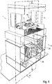
- the invention relates in particular to a system for coating workpieces 1 in the form of bodies 6, as shown in a first exemplary embodiment.
- This system comprises an air duct system 2 and a work area (paint booth 3).
- a separating device 4 according to the invention is provided adjacent to the painting booth 3, in particular below it.
- the air duct system 2 guides a gas flow 5 through the painting booth 3 and the separation device 4.
- the air duct system 2 comprises a fan 7 and a conditioning device 8.
- the fan 7 conveys the gas flow 5 through the painting booth 3 and the separating device 4. At least part of the gas flow 5 is also passed through the conditioning device 8, with a view to temperature and / or Moisture conditioned.
- the painting booth 3 comprises a conveying device 9 for conveying a body 6 and an application device 10 for applying paint to a body 6.
- an application device 10 for applying paint to a body 6.
- solid, liquid and / or pasty particles in the form of paint overspray particles 11 get in the gas flow 5.
- a gas flow 5 enriched with paint overspray particles 11 is preferably a raw gas flow 12.
- the separator 4 has a pre-separator, a main separator and a post-separator.
- the raw gas stream 12 first passes the pre-separator and then one after the other the main separator and the post-separator.
- the raw gas stream 12 has a higher number of paint overspray particles 11 when it enters the separation device 4 than it does when it exits the separation device 4.
- a gas stream 5 exiting from the separation device 4 is preferably a clean gas stream 36.
- the pre-separator is designed as an impact separator 13 and comprises eight structurally identical separator elements 14, 15, 16, 17, 18, 19, 20, 21 and one Regeneration device 22. Outer contours of adjacent separation elements 14, 15, 16, 17, 18, 19, 20, 21 intersect.
- the regeneration device 22 temporarily acts on a separation element and paint overspray particles 11 deposited thereon.
- the impact separator 13 also has at least two different zones arranged on a separation element, firstly a separation zone 23 and secondly a regeneration zone 24.
- a first separating element 15 of the impact separator 13 comprises a shaft 25 and eight structurally identical radial surface elements 15a, 15b, 15c, 15d, 15e, 15f, 15g, 15h, which are arranged protruding radially from the shaft 25.
- a (first) radial surface element 15a has two separation surfaces 15a 'and 15a ".
- a second radial surface element 15b has two separation surfaces 15b' and 15b" and a third radial surface element 15c has two separation surfaces 15c 'and 15c ".
- the other radial surface elements of the Separation element also has two separation surfaces.
- the remaining separation elements 14, 16, 17, 18, 19, 20, 21 are constructed in the same way as the first separation element 15.
- the separation surfaces of separation elements 14, 16 adjacent to the first separation element 15 are at a distance from the separation surfaces 15a ', 15a ", 15b', 15b", 15c ', 15c "of the first separation element 15.
- a (first) drive unit 27 is in a non-positive connection with the shaft 25.
- the first separating element 15 can change its position and assume at least two different working positions.
- the regeneration device 22 arranged downstream of a separation element comprises a cleaning system 29.
- the cleaning system 29 serves to remove paint overspray particles 11 from a separation surface.
- the cleaning system 29 has eight cleaning stamps 30a, 30b, 30c, 30d, 30e, 30f, 30g, 30h, which are arranged on a carrier device 31.
- the cleaning system 29 comprises a second drive unit 32, which is operatively connected to at least one cleaning ram, and a collecting container 33.
- the collecting container 33 is arranged below a separation element.
- At least one cleaning stamp is assigned to each of the separation elements.
- a first cleaning stamp 30b for example, is assigned to the first separation element 15.
- the main separator is designed as a filter fleece 34 and is arranged downstream of the pre-separator.
- the filter fleece 34 comprises a multiplicity of fiber elements and, due to its porous structure, the gas flow 5 and / or the raw gas flow 12 can flow through it.
- the post-separator is designed as a pocket filter 35 and is arranged downstream of the main separator.
- the gas stream after passing through the main separator, is fed to a conditioning device and then again to the painting booth.
- a post-separator is optionally available.
- the separation device 4 functions as follows.
- the raw gas stream 12 flows through the impact separator 13 in the main flow direction 28, at least some of the paint overspray particles 11 contained in the raw gas stream 12 being separated off.
- At least a partial flow of the raw gas flow 12 passes the first separation element 15 and at the same time the area between the first separation element 15 and a separation element 16 arranged adjacent to it, in which the outer contours of the two separation elements 15, 16 intersect.
- a first separation surface 15c ′′ assigned to the third radial surface element 15c is arranged in the separation zone 23 and a second separation surface 15a ′′ assigned to the first radial surface element 15a is arranged in the regeneration zone 24.
- the first separation surface 15c "a separation position and the second separation surface 15a" a regeneration position.
- the first separation surface 15c ′′ positioned in the separation zone 23 acts as a flow guide element when the raw gas flow 12 flows through the impact separator 13.
- a flow guide element deflects the raw gas flow 12 at certain points from the main flow direction 28 into a secondary flow direction 37
- Paint overspray particles 11 continue to follow the main flow direction 28 due to inertia effects and collide with the first separation surface 15c ′′. Paint overspray particles 11 are first deposited on the first separation surface 15c ′′ and are then physically bound to the first separation surface 15c ′′ by means of adhesion and cohesion forces. This at least temporary interaction between at least some of these paint overspray particles 11 and the first separation surface 15c ′′ removes these paint overspray particles 11 from the raw gas flow 12.
- paint overspray particles 11 are deposited on the first separation surface 15c ′′ of the first separation element positioned in the separation zone 23, paint overspray particles 11 are simultaneously removed from a second separation surface 15a ′′ of the same first separation element 15 positioned in the regeneration zone 24.
- the cleaning stamp 30b strips off paint overspray particles 11 that were previously deposited on the second separation surface 15a ′′. Stripped paint overspray particles 11 fall into the collecting container 33.
- the cleaning stamp 30b is returned to a Brought to the starting position.
- a second (not shown) working position in which the first separation element 15 is arranged rotated by 90 ° about the axis of rotation 26, the first separation surface 15c ′′ is arranged in the regeneration zone 24 and the second separation surface 15a ′′ in the Separation zone 23.
- the first separation surface 15c "assumes a regeneration position and the second separation surface 15a" assumes a separation position.
- the first separation element 15 is adjusted between a first and a second working position by rotating it about the axis of rotation 26. When the first separation element 15 is rotated completely through 360 °, a separation surface of the first separation element 15 passes through the separation zone 23 at least once and the regeneration zone 24 at least once .
- a collecting container has an insert made of cardboard, which reduces contamination of the collecting container.
- Such an insert preferably fits positively into the collecting container and can be removed for cleaning purposes.
- a pre-separator has a single separating element with a plurality of separating surfaces.
- the raw gas stream 12 flows through the filter fleece 34. At least some of the paint overspray particles 11 that have passed through the impact separator 13 are separated out.
- the raw gas stream 12 flows through the pocket filter 35.
- the paint overspray particles 11 that have passed through the impact separator 13 and the filter fleece 34 are separated.
- a gas stream 5 that has passed the separation device 4 is preferably a pure gas stream 36.
- a portion of the clean gas flow 36 is removed from the clean gas flow 36 as exhaust air flow 38 and a fresh air flow 39 is fed to the clean gas flow 36.
- the clean gas stream 36 then flows through the Conditioning device 8.
- the pure gas stream 36 is then fed again to the painting booth 3 as gas stream 5.
- a pre-separator serves to protect a downstream main and / or post-separator.
- the pre-separator removes some of the paint overspray particles 11 from the raw gas flow 12, so that the main separator and / or the post-separator have to separate out fewer paint overspray particles 11. Thereby the main and / or the post-separator can be relieved, and the service life of the main separator and / or the post-separator can be extended.
- a separation element of a pre-separator comprises a plurality of radial surface elements with a plurality of separation surfaces which are provided with a plurality of passage openings.
- the passage openings are arranged on the separation surfaces in such a way that a raw gas flow which passes the pre-separator and hits the separation surface in the process passes through these passage openings. Particles contained in the raw gas flow, in particular paint overspray particles, are deposited on the separation surface.
- the passage openings are therefore located in the flow path of the raw gas flow.
- a separation surface with a passage opening filters particles contained in the raw gas flow out of the raw gas flow, in that the passage opening for gaseous components of the raw gas flow can be passed, while solid and / or liquid components such as particles and / or paint overspray particles are at least partially separated on the separation surface.
- a separation surface is preferably formed from a polymer, a ceramic and / or a metallic material.
- the passage openings can be through bores in a solid material, through intermediate spaces and / or material-free spaces in a sintered material and / or be formed by intermediate spaces and / or material-free spaces in a fibrous tissue material.
- a perforated plate, a foam, a fiber mat, an expanded metal, a sintered metal, a sintered ceramic and / or a sintered plastic can be provided here.
- FIG. 7 and 8th The illustrated second embodiment of a separation device 4 differs from that in FIG Figures 1 to 6 illustrated first embodiment essentially by a differently designed cleaning system.
- a cleaning system essentially comprises a blasting device 40, with the aid of which a blasting agent can be brought into interaction with a separation surface.
- the blasting device 40 has a carrier system 43, several blasting nozzles 41 attached to the carrier system 43 and a unit for supplying blasting media 42.
- the blasting agent supply unit 42 comprises a storage container and conveys the blasting agent from this storage container to a blasting nozzle 41.
- a blasting nozzle 41 is aligned with a separation element in such a way that a jet emerging from the blasting nozzle 41 strikes the separation element.
- Solid carbon dioxide (so-called dry ice) is used as the blasting agent.
- the blasting agent is put under pressure in the blasting device 40 and leaves the blasting device 40 via a blasting nozzle 41.
- the separating device in a system for coating workpieces 1 according to embodiment 2 functions as follows.
- a separation surface 15a ′′ is arranged in a separation position in a separation zone 23 and picks up paint overspray particles 11 which are separated from a raw gas stream 12.
- the separation element 15 rotates about the axis of rotation 26 into a different, second working position (not shown).
- the separation surface 15a ′′ is arranged in a regeneration position in a regeneration zone 24.
- the abrasive is the blasting device 40 is released into space via a blasting nozzle 41. Due to the kinetic energy stored in the blasting media and the alignment of the blasting nozzle 41, the blasting media moves in the direction of the separation surface 15a ".
- this kinetic energy is transferred at least in part by the blasting media to those paint overspray particles 11 which are on the separation surface 15a" have been deposited, and removes these paint overspray particles 11 from the separation surface 15a ".
- the separation element 15 can be brought into a third working position by a further rotation (in the same or opposite direction) around the axis of rotation 26, in which the separation surface 15a" is again arranged in a separation zone 23 and can be subjected to a separation process.
- compressed air is used as a blasting agent as an alternative or in addition to dry ice.
- the components of the compressed air essentially nitrogen and oxygen molecules, are released via a jet nozzle and then hit a separation surface on which paint overspray particles have previously been separated.
- a cleaning system has a jet nozzle that is movably arranged and can be positioned by adjustment in such a way that this jet nozzle can first remove paint overspray particles from a first area of a separation surface and then paint overspray particles from another area of the same separation surface.
- a cleaning system has an additional drive unit for moving one or more jet nozzles.
- a cleaning system has a jet nozzle which is movably arranged and can be positioned by adjusting in such a way that this jet nozzle can first remove paint overspray particles from a separation surface of a separation element and then paint overspray particles from a separation surface of another separation element.
- FIG. 9 and Figure 10 The illustrated third exemplary embodiment of a separation device 4 differs essentially from the first exemplary embodiment in that a regeneration device has an auxiliary material system 44 in addition to a cleaning system.
- An auxiliary material system 44 serves to apply an auxiliary material to a deposition surface of a deposition element.
- the auxiliary material system 44 comprises a unit for supplying auxiliary material 45 and a plurality of auxiliary material nozzles 46 attached to a holding device.
- the unit for supplying auxiliary material 45 comprises a storage container and conveys auxiliary material from this storage container to an auxiliary material nozzle 46.
- Limestone powder is used as an auxiliary material. Limestone powder particles physically interact with paint overspray particles on contact.
- the separation device according to embodiment 3 functions as follows.
- a first separation surface is arranged in a regeneration zone and a second separation surface is arranged in a separation zone.
- Limestone powder particles are applied to the first separation surface by means of an auxiliary material nozzle 46.
- Limestone powder particles preferably form a separating layer between a separation surface and paint overspray particles.
- paint overspray particles are deposited on the second separation surface, which are part of a raw gas flow that passes through the separation device.
- the separation element After a certain time, the separation element is moved into a second working position so that the first separation surface is arranged in a separation zone and paint overspray particles can be separated on it.
- the cleaning system limestone dust particles and paint overspray particles are removed from the second separation surface, which is arranged in a regeneration zone.
- powdered limestone particles are then again applied to the second separation surface as a separating layer.
- a spray film is used as an auxiliary material instead of limestone powder particles.
- a spray film contains one or more liquid ones Components that are applied to a deposition surface and form a layer there by running.
- a physical and / or chemical reaction of a component optionally with another component and / or a reaction gas, e.g. air, a solid, film-like substance is formed, which acts as a separating layer between a separation surface and a paint overspray particle and in a regeneration step can be deducted.
- a fat is used as an auxiliary material.
- the fat preferably comprises one or more hydrocarbon compounds which are solid and / or viscous at room temperature.
- the fat can, for example, be atomized by means of pressure and applied to a radial surface element of a separation element with the aid of an auxiliary material nozzle.
- the applied grease acts as a separating layer between the radial surface element and the paint overspray particles and facilitates cleaning of the radial surface element.
- a cleaning system is used which acts, for example, physically and / or chemically on the separated paint overspray particles and / or the grease.
- Such a cleaning system preferably comprises a cleaning stamp and / or a jet device for applying a cleaning fluid such as water, alcohol and / or compressed air.
- the separation surfaces include a plurality of passage openings, the separation surfaces being at least temporarily provided with an auxiliary material when the separation device is in operation and can be cleaned with the aid of a cleaning system.
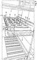
- FIG. 11 The fourth embodiment of a separation device 4 shown differs from that in FIG Figures 1 to 9 illustrated embodiments essentially in that several separation elements are arranged in different depth positions.
- a vertically oriented primary auxiliary plane 47 is laid through the separating device 4.
- a first group of separation elements 49 is arranged in the primary auxiliary plane 47, the axes of rotation of the separation elements of this first group of separation elements 49 lie in the primary auxiliary plane 47.
- the first group of separation elements 49 comprises three separation elements.
- a vertically oriented secondary auxiliary plane 48 is also laid through the separating device 4.
- a second group of separation elements 50 is arranged in the secondary auxiliary plane 48, the axes of rotation of the separation elements of this second group of separation elements 50 lying in the secondary auxiliary plane 48.
- the second group of separation elements 50 comprises two separation elements.
- the primary auxiliary plane 47 and the secondary auxiliary plane 48 are arranged one after the other in the main flow direction 28 as well as parallel and at a certain distance from one another.
- a raw gas stream 12 which flows through the separation device 4 in the main flow direction 28, first crosses the primary auxiliary plane 47 and then the secondary auxiliary plane 48. If separating elements are arranged in a separating device in different depth positions, more separating elements can be arranged in the separating device with the same width of the separating device or, if the separating device is smaller, the same number of separating elements can be arranged in the separating device than if separating elements are arranged in a deep position.
- a second group of separation elements arranged in the second auxiliary plane is designed to be displaceable on an axis arranged parallel to the main flow direction.
- the distance between a first group of separation elements arranged in the primary auxiliary plane on the one hand and a second group of separation elements arranged in the secondary auxiliary plane on the other hand changes. If a group of separation elements is designed to be displaceable in this way, a distance between several groups of separation elements can be increased, for example, at least temporarily. This increases the distance between a separation surface of a separation element of the one group of separation elements and a separation surface of a separation element of the other group of separation elements.
- FIG. 12 An in Figure 12
- the illustrated fifth embodiment of a separation device 4 differs from that in FIG Figures 1 to 11 illustrated embodiments essentially in that four separation elements are provided. Furthermore, the separating device 4 differs in that the separating elements are designed alternatively.
- Such a first alternative embodiment of a separation element 51 has, in particular, a plurality of surface elements 54 ', 54 ", 54"' with separation surfaces arranged differently.
- a first differently arranged separation surface 52 'and a second differently arranged separation surface 52 "arranged in the main flow direction 28 after the first differently arranged separation surface 52' have a largely parallel alignment to one another.
- a third differently arranged separation surface 52 '" has a largely vertical orientation the two aforementioned separation surfaces.
- the first alternative embodiment of a separation element 51 is changed from the first to a second working position by rotating about an axis of rotation 26 adjusted. After this rotation, the first differently arranged separation surface 52 'and the second differently arranged separation surface 52 "are positioned in the regeneration zone 24, and the third differently arranged separation surface 52"' in the separation zone 23. While of the first differently arranged separation surface 52 'and the second differently arranged separation surface 52 "paint overspray particles 11 are removed, are deposited on the third differently arranged separation surface 52" paint overspray particles 11.
- FIG. 13 An in Figure 13 The illustrated sixth embodiment of a separation device 4 is arranged in a system for coating workpieces 1, which, in contrast to the previous embodiments, is used to paint parts and / or add-on parts of car bodies, such as hoods, doors, side parts, front flaps, tailgates, bumpers and / or exterior mirror housings.
- the separation device 4 differs from that in FIG Figures 1 to 12 illustrated embodiments essentially by a second alternative configuration of a separation element 53. In the separation device 4 according to embodiment 6, three separation elements of a second alternative configuration are provided.
- Such a second alternative embodiment of a separation element 53 has in particular a shaft 25, several differently configured radial surface elements 55 and several differently configured separation surfaces 56.
- a differently configured radial surface element 55 is arranged so as to project radially on the shaft 25.
- a retaining element 57 is provided at an end of the differently configured radial surface element 55 opposite to the shaft 25, .
- the retaining element 57 protrudes at an angle of 45 ° to 90 °, preferably perpendicular, from the radial surface element 55 configured differently.
- a retaining element 57 acts as a barrier for a raw gas flow 12 passing through the separating device 4 and for paint overspray particles 11 deposited on a differently configured separation surface 56 of the differently configured radial surface element 55.
- the retaining element 57 at least partially prevents paint overspray particles 11 from being separated from the raw gas flow 12 flowing past get carried away.
- FIG. 14 The illustrated seventh embodiment of a separation device 4 differs from that in FIG Figures 1 to 13 illustrated embodiments essentially by a third alternative embodiment of a separation element 58.
- a first alternatively arranged axis of rotation 59 is aligned parallel to a central longitudinal axis 60 of the separation element and is arranged at a certain distance from this central longitudinal axis 60.
- separating elements are arranged in a row and are rotated about their respective axis of rotation, the axes of rotation arranged offset with respect to a central longitudinal axis cause a varying distance between the separating elements.
- a flow velocity and / or a pressure loss of the raw gas flow 12 and / or a degree of separation of the impact separator 13 can thus be influenced.
- a further alternative embodiment of a separation element has an axis of rotation which intersects a central longitudinal axis of the separation element at a point within an outer contour of the separation element.
- an axis of rotation of a separating element is designed to be adjustable with respect to the position and / or the alignment.
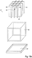
- FIG. 15a and 15b The eighth embodiment of a separation device 4 shown differs from that in FIG Figures 1 to 14 illustrated embodiments essentially in that a folded cardboard filter 61 is provided as the main separator.
- a plurality of folded cardboard filters 61 are arranged next to and above one another in a grid; in the exemplary embodiment described here, there are nine folded cardboard filters 61 overall, arranged in a grid with three folding cardboard filters 61 next to one another and three folding cardboard filters 61 one above the other.
- a folded cardboard filter 61 comprises an inner element 62 and an outer element 63 and optionally a tub element 64, an inner element 62 being temporarily arranged within an outer element 63 and an outer element 63 being arranged temporarily in a tub element 64.
- An inner element 62 has a wall section 65 with a plurality of passage and / or deflection openings 66.
- the raw gas stream 12 flows through the passage and / or deflection openings 66, while paint overspray particles 11 are deposited on closed partial areas of a wall section 65.
- the raw gas stream 12 enters the folded cardboard filter 61 in a main flow direction 28, passes through it and is deflected several times. During the deflection, paint overspray particles 11 are deposited on a closed partial area of a wall section 65 of the folded cardboard filter 61 with the aid of inertia effects.
- a folded cardboard filter 61 If the separation effect of a folded cardboard filter 61 is reduced and / or exhausted, it is removed from the separation device 4 and replaced by a new folded cardboard filter 61 or by a cleaned and / or processed folded cardboard filter 61.
- several folded cardboard filters are arranged one after the other in the main flow direction, so that a raw gas stream flows through the folded cardboard filters one after the other.
- a folded cardboard filter is conical.
- a vertical cross-sectional area of the folded cardboard filter decreases in the main flow direction.
- a main separator preferably has a receptacle device that is negative in relation to the folded cardboard filter.
- a folded cardboard filter designed in this way can be due to a centering effect caused by the conical shape particularly easy to install in the main separator and to be removed from it again.
- a system with rigid-body filter elements can be used as the main separator, with rigid-body filter elements preferably being made of a polymer material.
- Rigid filter elements act as regenerable surface filters, the surface of which can be protected from paint overspray particles with a barrier layer formed from an auxiliary material.
- an electrostatic wet separation system can be used as the main separator. Paint overspray particles are first electrically charged using a corona electrode and then deposited on a grounded separation electrode.
- an electrostatic wet separation system has a liquid system that contains a substance and / or a mixture of substances with liquid, waxy and / or includes pasty components.
- the substance and / or the mixture of substances wet the separation electrode and absorb paint overspray particles that strike it.
- the substance is preferably a release agent.
- a main separator designed as a hybrid filter is used.
- a hybrid filter has several differently acting partial separation systems and, in addition to a cardboard material, comprises a fibrous plastic material and a wood material.
- Partial separation systems with different effects are formed from the cardboard material and from the fibrous plastic material, which, for example, can separate paint overspray particles of different particle sizes to different degrees.
- a first partial separation system comprises a surface filter, on the surface of which paint overspray particles can be separated.
- a second partial separation system comprises a depth filter that can absorb paint overspray particles into its interior.
- the wood material fulfills a support and stabilization function and preferably reinforces the hybrid filter.
- a separation device is arranged only on one side of an auxiliary plane configured as a vertical longitudinal center plane of a coating installation.
- auxiliary plane configured as a vertical longitudinal center plane of a coating installation.
- a separation surface is formed from a ferromagnetic material in the form of a steel alloy and has a magnetic coil.
- An auxiliary material for protecting the separation surface then comprises in particular a ferromagnetic material in the form of iron powder.
- the separation device comprises a jet device with which a jet of compressed air can be directed onto the separation surface.
- a separation surface is designed from a hard magnetic material in the form of an iron alloy.
- An auxiliary material for protecting the separation surface then comprises in particular a ferrofluid in the form of a colloidal suspension of iron in water.
- the separation device comprises a cleaning stamp in order to remove separated paint overspray particles and auxiliary material from the separation surface.
- the cleaning ram is moved along the separation surface.
- a separation surface is covered with a film material.
- a film material acts as a separating layer between a separation surface and paint overspray particles. At certain time intervals, a film material together with the paint overspray particles deposited on it can be removed from the separation surface and replaced by new, fresh and / or cleaned film material.
- a cardboard material can be used as an alternative or in addition to a film material.
- a separating element is arranged lying horizontally in a preseparator. A main flow direction of a raw gas flow through the pre-separator is then oriented essentially vertically.
- a perforated plate is arranged downstream of a main separator, which has holes at certain points and which, with its external dimensions, fills the free cross section of the separating device.
- the perforated plate causes a more even flow through the separation device.
Landscapes
- Chemical & Material Sciences (AREA)
- Chemical Kinetics & Catalysis (AREA)
- Combined Means For Separation Of Solids (AREA)
- Sampling And Sample Adjustment (AREA)
- Separating Particles In Gases By Inertia (AREA)
Claims (12)
- Dispositif de séparation (4) pour la séparation de particules d'un courant de gaz brut (12), une proportion de particules solides, liquides et/ou pâteuses pouvant être entraînée dans le courant de gaz brut, pourvu d'un séparateur principal, qui sépare au moins une partie des particules du courant de gaz brut, le courant de gaz brut traversant le séparateur principal dans une direction de traversée principale (28) et sortant du séparateur principal sous la forme d'un courant de gaz pur (36),- le dispositif de séparation comprenant un séparateur préliminaire pour la séparation d'au moins une partie des particules du courant de gaz brut,- le séparateur préliminaire étant agencé en amont du séparateur principal de telle sorte que le courant de gaz brut traverse dans la direction de traversée principale tout d'abord le séparateur préliminaire et ensuite le séparateur principal,- le séparateur préliminaire comportant un élément de séparation (14, 15, 16, 17, 18, 19, 20, 21, 51, 53, 58), qui est prévu pour dévier le courant de gaz brut (12), l'élément de séparation comportant un arbre (25), ainsi qu'un élément de surface radial (15a, 15b, 15c, 15d, 15e, 15f, 15g, 15h), qui est agencé sur l'arbre en saillie radialement à partir de l'arbre, et qui comprend une surface de séparation (15a', 15a", 15b', 15b", 15c', 15c", 52', 52", 52"', 56) agencée sur l'élément de surface radial, sur laquelle des particules peuvent être séparées du courant de gaz brut,- des contours externes de deux éléments de séparation agencés voisins l'un de l'autre se coupant, le contour externe d'un élément de séparation étant la surface d'un corps configuré sous forme approximativement cylindrique et/ou prismatique fictif,- un élément de séparation (14, 15, 16, 17, 18, 19, 20, 21, 51, 53, 58) étant configuré rotatif en continu ou par intervalles autour d'un axe de rotation (26, 59), afin de déplacer l'élément de séparation entre plusieurs positions de travail, et comprenant au moins deux surfaces de séparation (15a', 15a", 15b', 15b", 15c', 15c", 52', 52", 52"', 56) pour la séparation de particules, dans une première position de travail de l'élément de séparation, une surface de séparation de l'élément de séparation se trouvant dans un emplacement de séparation, tandis que simultanément une autre surface de séparation du même élément de séparation se trouve dans un emplacement de régénération,- une surface de séparation (15a', 15a", 15b', 15b", 15c', 15c", 52', 52", 52"', 56) de l'élément de séparation (14, 15, 16, 17, 18, 19, 20, 21, 51, 53, 58) dans un emplacement de séparation agissant en tant qu'élément de conduction d'écoulement, qui pénètre dans la trajectoire d'écoulement du courant de gaz brut (12),- au moins à chaque fois une surface de séparation agissant en tant qu'élément de conduction d'écoulement de deux éléments de séparation agencés voisins réalisant ensemble une déviation du courant de gaz brut de la direction de traversée principale (28), ce qui entraîne une séparation des particules contenues dans le courant de gaz brut sur les surfaces de séparation en raison de l'inertie de masse,- les surfaces de séparation de deux éléments de séparation agencés voisins étant agencées l'une après l'autre dans la direction de traversée principale de telle sorte qu'elles soient balayées successivement par le courant de gaz brut,caractérisé en ce que
les surfaces de séparation de deux éléments de séparation agencés voisins l'un de l'autre présentent un écart l'une par rapport à l'autre. - Dispositif de séparation (4) selon la revendication 1, caractérisé en ce que le séparateur préliminaire comporte un élément de séparation (14, 15, 16, 17, 18, 19, 20, 21, 51, 53, 58), qui comprend une ouverture de passage pour le passage d'une partie du courant de gaz brut (12).
- Dispositif de séparation (4) selon l'une quelconque des revendications 1 ou 2, caractérisé en ce qu'un revêtement en un matériau auxiliaire est associé au moins en sections avec la surface de séparation (15a', 15a", 15b', 15b", 15c', 15c", 52', 52", 52'", 56), qui interagit chimiquement et/ou physiquement avec certaines particules.
- Dispositif de séparation (4) selon l'une quelconque des revendications 1 à 3, caractérisé en ce que- un revêtement de la surface de séparation (15a', 15a", 15b', 15b", 15c', 15c", 52', 52", 52"', 56) est formé en un matériau auxiliaire, qui comporte un matériau ferromagnétique, et en ce que- le séparateur préliminaire comprend une bobine magnétique et/ou un aimant permanent pour une application continue ou par intervalles d'un champ magnétique à la surface de séparation.
- Dispositif de séparation (4) selon l'une quelconque des revendications 1 à 4, caractérisé en ce que le séparateur préliminaire comprend un dispositif de régénération pourvu d'un système de nettoyage, qui élimine- au moins une partie des particules séparées sur une surface de séparation (15a', 15a", 15b', 15b", 15c', 15c", 52', 52", 52"', 56) d'un élément de séparation (14, 15, 16, 17, 18, 19, 20, 21, 51, 53, 58),- au moins une partie d'un matériau auxiliaire séparé sur une surface de séparation d'un élément de séparation et/ou- au moins une partie d'un système, constitué par des particules et du matériau auxiliaire, séparé sur une surface de séparation d'un élément de séparation, de la surface de séparation de l'élément de séparation.
- Dispositif de séparation (4) selon l'une quelconque des revendications 1 à 5, caractérisé en ce que le dispositif de séparation comprend un séparateur principal, qui sépare au moins une partie des particules, qui sont passées au travers du séparateur préliminaire, du courant de gaz brut (12), le séparateur principal étant configuré sous la forme d'un filtre en carton plié (61) et comportant un élément en carton plié.
- Dispositif de séparation (4) selon l'une quelconque des revendications 1 à 6, caractérisé en ce que plusieurs éléments de séparation (14, 15, 16, 17, 18, 19, 20, 21, 51, 53, 58) présentent une position en profondeur différente vis-à-vis de la direction de traversée principale (28), des axes de rotation (26, 59) d'éléments de séparation qui présentent une position en profondeur différente étant situés dans deux ou davantage de plans auxiliaires (47, 48) différents, agencés espacés les uns des autres et coupant le dispositif de séparation.
- Dispositif de séparation (4) selon l'une quelconque des revendications 1 à 7, caractérisé en ce que le séparateur préliminaire comporte au moins deux éléments de séparation (14, 15, 16, 17, 18, 19, 20, 21, 51, 53, 58),- au moins deux surfaces de séparation (15a', 15a", 15b', 15b", 15c', 15c", 52', 52", 52'", 56) étant associées à chaque élément de séparation, sur lesquelles des particules solides, liquides et/ou pâteuses peuvent être séparées du courant de gaz brut (12),- les surfaces de séparation étant revêtues par moments et/ou en sections avec un matériau auxiliaire, qui interagit chimiquement et/ou physiquement avec certaines particules du courant de gaz brut,- un élément de séparation étant configuré rotatif autour d'un axe de rotation (26, 59) au moyen d'une unité d'entraînement (27, 32), afin de déplacer l'élément de séparation entre plusieurs positions de travail, dans une première position de travail de l'élément de séparation, une surface de séparation de cet élément de séparation se trouvant dans un emplacement de séparation, tandis que simultanément une autre surface de séparation du même élément de séparation se trouve dans un emplacement de régénération,- une surface de séparation d'un élément de séparation se trouvant dans un emplacement de séparation agissant en tant qu'élément de conduction d'écoulement, qui pénètre dans la trajectoire d'écoulement du courant de gaz brut et conduit le courant de gaz brut lors du passage au travers du séparateur préliminaire,- le séparateur préliminaire comprenant un dispositif de régénération pourvu d'un système de nettoyage, qui élimine au moins une partie des particules séparées sur une surface de séparation d'un élément de séparation, au moins une partie du matériau auxiliaire séparé sur une surface de séparation d'un élément de séparation et/ou au moins une partie du système, constitué par des particules et du matériau auxiliaire, séparé sur une surface de séparation d'un élément de séparation, de la surface de séparation de l'élément de séparation.
- Unité pour le traitement, notamment pour le revêtement ou l'usinage de pièces (1), pourvue d'un dispositif de séparation selon l'une quelconque des revendications 1 à 8.
- Procédé pour la séparation de particules d'un courant de gaz brut (12) à l'aide d'un dispositif de séparation (4) selon l'une quelconque des revendications 1 à 8, qui comprend les étapes de procédé suivantes :- l'écoulement du courant de gaz brut au travers d'un séparateur préliminaire, et- l'écoulement du courant de gaz brut au travers d'un séparateur principal agencé en aval du séparateur préliminaire,- la direction d'écoulement du courant de gaz brut lors d'une traversée du séparateur préliminaire étant au moins par moments déviée d'une direction de traversée principale (28) et, en conséquence d'effets d'inertie de masse, au moins une partie des particules étant séparée du courant de gaz brut traversant le séparateur préliminaire sur une surface de séparation (15a', 15a", 15b', 15b", 15c', 15c", 52', 52", 52"', 56) d'un élément de séparation (14, 15, 16, 17, 18, 19, 20, 21, 51, 53, 58), l'élément de séparation comportant un arbre (25), ainsi qu'un élément de surface radial (15a, 15b, 15c, 15d, 15e, 15f, 15g, 15h) qui est agencé sur l'arbre en saillie radialement à partir de l'arbre, la surface de séparation étant agencée sur l'élément de surface radial,- le courant de gaz brut traversant une zone dans le séparateur préliminaire, dans laquelle les contours externes de deux éléments de séparation agencés voisins l'un de l'autre se coupent, et- qui est formée par un écart entre des surfaces de séparation de deux éléments de séparation agencés voisins l'un de l'autre,- le contour externe d'un élément de séparation étant la surface d'un corps configuré sous forme approximativement cylindrique et/ou prismatique fictif,- un élément de séparation (14, 15, 16, 17, 18, 19, 20, 21, 51, 53, 58) étant mis en rotation autour d'un axe de rotation (26, 59), de telle sorte qu'une surface de séparation (15a', 15a", 15b', 15b", 15c', 15c", 52', 52", 52"', 56) de l'élément de séparation, qui avant la rotation autour de l'axe de rotation était tournée vers la direction de traversée principale (28) et sur laquelle le courant de gaz brut (12) affluait, soit détournée de la direction de traversée principale après la rotation autour de l'axe de rotation.
- Procédé selon la revendication 10, caractérisé en ce qu'au moins une partie du courant de gaz brut (12) passe au travers d'une ouverture de passage d'un élément de séparation (14, 15, 16, 17, 18, 19, 20, 21, 51, 53, 58) et au moins une partie des particules (12) est séparée sur l'élément de séparation.
- Procédé selon l'une quelconque des revendications 10 à 11, caractérisé en ce que des particules du courant de gaz brut (12) sont séparées sur une surface de séparation (15a', 15a", 15b', 15b", 15c', 15c", 52', 52", 52"', 56) d'un élément de séparation (14, 15, 16, 17, 18, 19, 20, 21, 51, 53, 58), tandis que simultanément une autre surface de séparation du même élément de séparation est soumise à un processus de régénération et ainsi régénérée, le processus de régénération comprenant les étapes individuelles suivantes :- l'élimination d'au moins une partie des particules, du matériau auxiliaire et/ou du système constitué par des particules et du matériau auxiliaire d'une surface de séparation d'un élément de séparation, et- le revêtement de la même surface de séparation du même élément de séparation avec du matériau auxiliaire frais et/ou conditionné.
Applications Claiming Priority (2)
| Application Number | Priority Date | Filing Date | Title |
|---|---|---|---|
| DE102015002498.1A DE102015002498A1 (de) | 2015-02-27 | 2015-02-27 | Abscheidevorrichtung zum Abscheiden von Partikeln |
| PCT/EP2016/052508 WO2016134953A1 (fr) | 2015-02-27 | 2016-02-05 | Dispositif de séparation pour la séparation de particules |
Publications (2)
| Publication Number | Publication Date |
|---|---|
| EP3268109A1 EP3268109A1 (fr) | 2018-01-17 |
| EP3268109B1 true EP3268109B1 (fr) | 2020-12-09 |
Family
ID=55304999
Family Applications (1)
| Application Number | Title | Priority Date | Filing Date |
|---|---|---|---|
| EP16703133.5A Active EP3268109B1 (fr) | 2015-02-27 | 2016-02-05 | Dispositif de séparation pour la séparation de particules |
Country Status (4)
| Country | Link |
|---|---|
| EP (1) | EP3268109B1 (fr) |
| CN (1) | CN108633262B (fr) |
| DE (1) | DE102015002498A1 (fr) |
| WO (1) | WO2016134953A1 (fr) |
Families Citing this family (5)
| Publication number | Priority date | Publication date | Assignee | Title |
|---|---|---|---|---|
| CN107596803A (zh) * | 2017-10-11 | 2018-01-19 | 中国汽车工业工程有限公司 | 一种纸盒干式漆雾过滤模块 |
| CN108499249B (zh) * | 2018-06-13 | 2023-11-17 | 中冶长天国际工程有限责任公司 | 一种工业除尘用除尘箱 |
| CN109847936B (zh) * | 2019-04-03 | 2024-02-20 | 河海大学 | 一种结合磁流体液膜的固废基大气雾霾静电吸附装置 |
| DE102019124965B4 (de) | 2019-09-17 | 2022-08-25 | Audi Ag | Öleinfanganordnung zum Einfangen von Öltröpfchen aus einem Ölnebelstrom |
| JP7382695B2 (ja) * | 2020-07-09 | 2023-11-17 | パーカーエンジニアリング株式会社 | 塗料ミスト捕集装置 |
Family Cites Families (14)
| Publication number | Priority date | Publication date | Assignee | Title |
|---|---|---|---|---|
| CA1041865A (fr) * | 1975-06-27 | 1978-11-07 | Donald F. Gerdes | Securite incendie pour cabine de pistolage |
| SU1738307A1 (ru) * | 1990-05-22 | 1992-06-07 | Белгородский технологический институт строительных материалов им.И.А.Гришманова | Фильтр дл очистки газов от пыли |
| DE29707787U1 (de) * | 1997-04-30 | 1997-06-19 | Fa. Paul Rippert, 33442 Herzebrock-Clarholz | Filtermedium zur Trockenabscheidung |
| DE29714021U1 (de) * | 1997-08-06 | 1997-11-06 | H. Krantz-Tkt Gmbh, 51465 Bergisch Gladbach | Filterapparat zur Abscheidung von gasgetragenen partikelförmigen Schadstoffen |
| JP2004195631A (ja) * | 2002-12-13 | 2004-07-15 | Kinji Matsumoto | オイルミスト回収装置 |
| ITTO20040557A1 (it) * | 2004-08-06 | 2004-11-06 | Buscemi S N C Di Buscemi Lucia | Elemento filtrante e filtro comprendente una pluralita' di elementi filtranti impilati assialmente |
| DE102007040901A1 (de) | 2007-08-24 | 2009-02-26 | Dürr Systems GmbH | Filtervorrichtung und Verfahren zum Abtrennen von Nasslack-Overspray |
| CN201216899Y (zh) * | 2008-06-19 | 2009-04-08 | 沈阳电力机械总厂 | 鼓形旋转滤网 |
| CN201711254U (zh) * | 2010-01-06 | 2011-01-19 | 王宝根 | 漆雾自动静电吸附回收的喷涂房 |
| JP6105891B2 (ja) * | 2012-10-09 | 2017-03-29 | 日東電工株式会社 | フィルタ濾材およびフィルタ濾材の製造方法 |
| DE102013004082A1 (de) * | 2013-03-11 | 2014-09-11 | Eisenmann Ag | Verfahren zum Betreiben einer Oberflächenbehandlungsanlage, Satz von Filtermodulen und Oberflächenbehandlungsanlage |
| DE102013114646A1 (de) * | 2013-12-20 | 2015-06-25 | Dürr Systems GmbH | Reinigungsvorrichtung und Verfahren zum Reinigen eines Rohgasstroms |
| CN104043554B (zh) * | 2014-06-16 | 2016-04-06 | 陈文坤 | 一种喷房 |
| CN104209188B (zh) * | 2014-08-22 | 2016-11-09 | 成都代代吉前瞻科技股份有限公司 | 一种静电-dep除尘器 |
-
2015
- 2015-02-27 DE DE102015002498.1A patent/DE102015002498A1/de not_active Withdrawn
-
2016
- 2016-02-05 WO PCT/EP2016/052508 patent/WO2016134953A1/fr not_active Ceased
- 2016-02-05 EP EP16703133.5A patent/EP3268109B1/fr active Active
- 2016-02-05 CN CN201680012336.7A patent/CN108633262B/zh active Active
Non-Patent Citations (1)
| Title |
|---|
| None * |
Also Published As
| Publication number | Publication date |
|---|---|
| EP3268109A1 (fr) | 2018-01-17 |
| CN108633262B (zh) | 2021-04-09 |
| WO2016134953A1 (fr) | 2016-09-01 |
| DE102015002498A1 (de) | 2016-09-01 |
| CN108633262A (zh) | 2018-10-09 |
Similar Documents
| Publication | Publication Date | Title |
|---|---|---|
| EP3268109B1 (fr) | Dispositif de séparation pour la séparation de particules | |
| EP2736655B1 (fr) | Installation compacte de mise en peinture | |
| DE69431169T2 (de) | Pulverbeschichtungssystem | |
| EP2969243B1 (fr) | Procédé de conduite d'une installation de traitement de surface, ensemble de modules filtrants et installation de traitement de surface | |
| EP2671647B1 (fr) | Dispositif de séparation de brouillard de peinture | |
| EP4434638A2 (fr) | Installation de filtration, installation de peinture et procédé de fonctionnement d'une installation de filtration | |
| EP3245008B1 (fr) | Procédé permettant de faire fonctionner une installation de traitement de surface | |
| EP2512690B1 (fr) | Procédé et dispositif de précipitation électrostatique de peinture excédentaire | |
| DE202011107555U1 (de) | Filteranlage | |
| WO2009012892A2 (fr) | Dispositif de dépôts de l'excès de pulvérisation de peinture | |
| EP1372868A1 (fr) | Installation pour le peinturage a la poudre d'objets | |
| DE112017000093T5 (de) | Flüssigkeitsversorgungsdüsenstruktur zur Minimalmengenschmierung beim Hochgeschwindigkeitsfräsen, Abscheide- und Rückgewinnungseinheit und System | |
| AT519542B1 (de) | Abscheideverfahren, Abscheidevorrichtung und Anordnung einer Abscheidevorrichtung mit einer Holzbearbeitungsmaschine | |
| EP1704925B1 (fr) | Dispositif de séparation de l'excédent de peinture liquide | |
| AT8123U1 (de) | Filtereinrichtung | |
| EP2595760A1 (fr) | Unité de traitement et installation pour le traitement de surface d'objets | |
| EP0678059B1 (fr) | Dispositif collecteur pour recueillir la peinture pulverisee en exces dans des cabines de pulverisation | |
| EP1704926B1 (fr) | Dispositif de séparation de l'excédent de peinture liquide | |
| EP3132858B1 (fr) | Dispositif d'élimination d'excès de pulvérisation et installation de traitement de surface | |
| DE102009052655A1 (de) | Vorrichtung, System, Bauteil, Verfahren und Zusammensetzung zur Vermeidung von Ablagerungen eines Entsorgungsmittels in Beschichtungsanlagen | |
| DE202012012511U1 (de) | Sprühbeschichtungsanlage zur Trockenemaillierung von Objekten | |
| DE3234802C2 (de) | Pulververteiler für elektrostatische Lackierung | |
| DE102013114646A1 (de) | Reinigungsvorrichtung und Verfahren zum Reinigen eines Rohgasstroms | |
| DE102015016554A1 (de) | Vorrichtung zum Abscheiden von Overspray, Oberflächenbehandlungsanlage und Verfahren zum Abscheiden von Overspray | |
| DE102004049931B4 (de) | Vorrichtung und Verfahren zum Abscheiden von Flüssigkeits- und/oder Festkörperteilchen aus einem Gasstrom |
Legal Events
| Date | Code | Title | Description |
|---|---|---|---|
| STAA | Information on the status of an ep patent application or granted ep patent |
Free format text: STATUS: THE INTERNATIONAL PUBLICATION HAS BEEN MADE |
|
| PUAI | Public reference made under article 153(3) epc to a published international application that has entered the european phase |
Free format text: ORIGINAL CODE: 0009012 |
|
| STAA | Information on the status of an ep patent application or granted ep patent |
Free format text: STATUS: REQUEST FOR EXAMINATION WAS MADE |
|
| 17P | Request for examination filed |
Effective date: 20170706 |
|
| AK | Designated contracting states |
Kind code of ref document: A1 Designated state(s): AL AT BE BG CH CY CZ DE DK EE ES FI FR GB GR HR HU IE IS IT LI LT LU LV MC MK MT NL NO PL PT RO RS SE SI SK SM TR |
|
| AX | Request for extension of the european patent |
Extension state: BA ME |
|
| RIN1 | Information on inventor provided before grant (corrected) |
Inventor name: SCHOETTLE, FRANK |
|
| DAV | Request for validation of the european patent (deleted) | ||
| DAX | Request for extension of the european patent (deleted) | ||
| STAA | Information on the status of an ep patent application or granted ep patent |
Free format text: STATUS: EXAMINATION IS IN PROGRESS |
|
| 17Q | First examination report despatched |
Effective date: 20190717 |
|
| GRAP | Despatch of communication of intention to grant a patent |
Free format text: ORIGINAL CODE: EPIDOSNIGR1 |
|
| STAA | Information on the status of an ep patent application or granted ep patent |
Free format text: STATUS: GRANT OF PATENT IS INTENDED |
|
| INTG | Intention to grant announced |
Effective date: 20200729 |
|
| GRAS | Grant fee paid |
Free format text: ORIGINAL CODE: EPIDOSNIGR3 |
|
| GRAA | (expected) grant |
Free format text: ORIGINAL CODE: 0009210 |
|
| STAA | Information on the status of an ep patent application or granted ep patent |
Free format text: STATUS: THE PATENT HAS BEEN GRANTED |
|
| AK | Designated contracting states |
Kind code of ref document: B1 Designated state(s): AL AT BE BG CH CY CZ DE DK EE ES FI FR GB GR HR HU IE IS IT LI LT LU LV MC MK MT NL NO PL PT RO RS SE SI SK SM TR |
|
| REG | Reference to a national code |
Ref country code: GB Ref legal event code: FG4D Free format text: NOT ENGLISH |
|
| REG | Reference to a national code |
Ref country code: AT Ref legal event code: REF Ref document number: 1342827 Country of ref document: AT Kind code of ref document: T Effective date: 20201215 Ref country code: CH Ref legal event code: EP |
|
| REG | Reference to a national code |
Ref country code: DE Ref legal event code: R096 Ref document number: 502016011906 Country of ref document: DE |
|
| REG | Reference to a national code |
Ref country code: IE Ref legal event code: FG4D Free format text: LANGUAGE OF EP DOCUMENT: GERMAN |
|
| PG25 | Lapsed in a contracting state [announced via postgrant information from national office to epo] |
Ref country code: RS Free format text: LAPSE BECAUSE OF FAILURE TO SUBMIT A TRANSLATION OF THE DESCRIPTION OR TO PAY THE FEE WITHIN THE PRESCRIBED TIME-LIMIT Effective date: 20201209 Ref country code: NO Free format text: LAPSE BECAUSE OF FAILURE TO SUBMIT A TRANSLATION OF THE DESCRIPTION OR TO PAY THE FEE WITHIN THE PRESCRIBED TIME-LIMIT Effective date: 20210309 Ref country code: GR Free format text: LAPSE BECAUSE OF FAILURE TO SUBMIT A TRANSLATION OF THE DESCRIPTION OR TO PAY THE FEE WITHIN THE PRESCRIBED TIME-LIMIT Effective date: 20210310 Ref country code: FI Free format text: LAPSE BECAUSE OF FAILURE TO SUBMIT A TRANSLATION OF THE DESCRIPTION OR TO PAY THE FEE WITHIN THE PRESCRIBED TIME-LIMIT Effective date: 20201209 |
|
| PG25 | Lapsed in a contracting state [announced via postgrant information from national office to epo] |
Ref country code: SE Free format text: LAPSE BECAUSE OF FAILURE TO SUBMIT A TRANSLATION OF THE DESCRIPTION OR TO PAY THE FEE WITHIN THE PRESCRIBED TIME-LIMIT Effective date: 20201209 Ref country code: BG Free format text: LAPSE BECAUSE OF FAILURE TO SUBMIT A TRANSLATION OF THE DESCRIPTION OR TO PAY THE FEE WITHIN THE PRESCRIBED TIME-LIMIT Effective date: 20210309 Ref country code: LV Free format text: LAPSE BECAUSE OF FAILURE TO SUBMIT A TRANSLATION OF THE DESCRIPTION OR TO PAY THE FEE WITHIN THE PRESCRIBED TIME-LIMIT Effective date: 20201209 |
|
| REG | Reference to a national code |
Ref country code: NL Ref legal event code: MP Effective date: 20201209 |
|
| PG25 | Lapsed in a contracting state [announced via postgrant information from national office to epo] |
Ref country code: HR Free format text: LAPSE BECAUSE OF FAILURE TO SUBMIT A TRANSLATION OF THE DESCRIPTION OR TO PAY THE FEE WITHIN THE PRESCRIBED TIME-LIMIT Effective date: 20201209 Ref country code: NL Free format text: LAPSE BECAUSE OF FAILURE TO SUBMIT A TRANSLATION OF THE DESCRIPTION OR TO PAY THE FEE WITHIN THE PRESCRIBED TIME-LIMIT Effective date: 20201209 |
|
| REG | Reference to a national code |
Ref country code: LT Ref legal event code: MG9D |
|
| PG25 | Lapsed in a contracting state [announced via postgrant information from national office to epo] |
Ref country code: RO Free format text: LAPSE BECAUSE OF FAILURE TO SUBMIT A TRANSLATION OF THE DESCRIPTION OR TO PAY THE FEE WITHIN THE PRESCRIBED TIME-LIMIT Effective date: 20201209 Ref country code: PT Free format text: LAPSE BECAUSE OF FAILURE TO SUBMIT A TRANSLATION OF THE DESCRIPTION OR TO PAY THE FEE WITHIN THE PRESCRIBED TIME-LIMIT Effective date: 20210409 Ref country code: SK Free format text: LAPSE BECAUSE OF FAILURE TO SUBMIT A TRANSLATION OF THE DESCRIPTION OR TO PAY THE FEE WITHIN THE PRESCRIBED TIME-LIMIT Effective date: 20201209 Ref country code: CZ Free format text: LAPSE BECAUSE OF FAILURE TO SUBMIT A TRANSLATION OF THE DESCRIPTION OR TO PAY THE FEE WITHIN THE PRESCRIBED TIME-LIMIT Effective date: 20201209 Ref country code: EE Free format text: LAPSE BECAUSE OF FAILURE TO SUBMIT A TRANSLATION OF THE DESCRIPTION OR TO PAY THE FEE WITHIN THE PRESCRIBED TIME-LIMIT Effective date: 20201209 Ref country code: LT Free format text: LAPSE BECAUSE OF FAILURE TO SUBMIT A TRANSLATION OF THE DESCRIPTION OR TO PAY THE FEE WITHIN THE PRESCRIBED TIME-LIMIT Effective date: 20201209 Ref country code: SM Free format text: LAPSE BECAUSE OF FAILURE TO SUBMIT A TRANSLATION OF THE DESCRIPTION OR TO PAY THE FEE WITHIN THE PRESCRIBED TIME-LIMIT Effective date: 20201209 |
|
| PG25 | Lapsed in a contracting state [announced via postgrant information from national office to epo] |
Ref country code: PL Free format text: LAPSE BECAUSE OF FAILURE TO SUBMIT A TRANSLATION OF THE DESCRIPTION OR TO PAY THE FEE WITHIN THE PRESCRIBED TIME-LIMIT Effective date: 20201209 |
|
| REG | Reference to a national code |
Ref country code: DE Ref legal event code: R097 Ref document number: 502016011906 Country of ref document: DE |
|
| PG25 | Lapsed in a contracting state [announced via postgrant information from national office to epo] |
Ref country code: MC Free format text: LAPSE BECAUSE OF FAILURE TO SUBMIT A TRANSLATION OF THE DESCRIPTION OR TO PAY THE FEE WITHIN THE PRESCRIBED TIME-LIMIT Effective date: 20201209 Ref country code: IS Free format text: LAPSE BECAUSE OF FAILURE TO SUBMIT A TRANSLATION OF THE DESCRIPTION OR TO PAY THE FEE WITHIN THE PRESCRIBED TIME-LIMIT Effective date: 20210409 |
|
| PLBE | No opposition filed within time limit |
Free format text: ORIGINAL CODE: 0009261 |
|
| STAA | Information on the status of an ep patent application or granted ep patent |
Free format text: STATUS: NO OPPOSITION FILED WITHIN TIME LIMIT |
|
| REG | Reference to a national code |
Ref country code: BE Ref legal event code: MM Effective date: 20210228 |
|
| PG25 | Lapsed in a contracting state [announced via postgrant information from national office to epo] |
Ref country code: LU Free format text: LAPSE BECAUSE OF NON-PAYMENT OF DUE FEES Effective date: 20210205 Ref country code: LI Free format text: LAPSE BECAUSE OF NON-PAYMENT OF DUE FEES Effective date: 20210228 Ref country code: AL Free format text: LAPSE BECAUSE OF FAILURE TO SUBMIT A TRANSLATION OF THE DESCRIPTION OR TO PAY THE FEE WITHIN THE PRESCRIBED TIME-LIMIT Effective date: 20201209 Ref country code: CH Free format text: LAPSE BECAUSE OF NON-PAYMENT OF DUE FEES Effective date: 20210228 |
|
| 26N | No opposition filed |
Effective date: 20210910 |
|
| GBPC | Gb: european patent ceased through non-payment of renewal fee |
Effective date: 20210309 |
|
| PG25 | Lapsed in a contracting state [announced via postgrant information from national office to epo] |
Ref country code: DK Free format text: LAPSE BECAUSE OF FAILURE TO SUBMIT A TRANSLATION OF THE DESCRIPTION OR TO PAY THE FEE WITHIN THE PRESCRIBED TIME-LIMIT Effective date: 20201209 Ref country code: SI Free format text: LAPSE BECAUSE OF FAILURE TO SUBMIT A TRANSLATION OF THE DESCRIPTION OR TO PAY THE FEE WITHIN THE PRESCRIBED TIME-LIMIT Effective date: 20201209 |
|
| PG25 | Lapsed in a contracting state [announced via postgrant information from national office to epo] |
Ref country code: ES Free format text: LAPSE BECAUSE OF FAILURE TO SUBMIT A TRANSLATION OF THE DESCRIPTION OR TO PAY THE FEE WITHIN THE PRESCRIBED TIME-LIMIT Effective date: 20201209 Ref country code: GB Free format text: LAPSE BECAUSE OF NON-PAYMENT OF DUE FEES Effective date: 20210309 Ref country code: IE Free format text: LAPSE BECAUSE OF NON-PAYMENT OF DUE FEES Effective date: 20210205 |
|
| REG | Reference to a national code |
Ref country code: AT Ref legal event code: MM01 Ref document number: 1342827 Country of ref document: AT Kind code of ref document: T Effective date: 20210205 |
|
| PG25 | Lapsed in a contracting state [announced via postgrant information from national office to epo] |
Ref country code: AT Free format text: LAPSE BECAUSE OF NON-PAYMENT OF DUE FEES Effective date: 20210205 |
|
| PG25 | Lapsed in a contracting state [announced via postgrant information from national office to epo] |
Ref country code: IS Free format text: LAPSE BECAUSE OF FAILURE TO SUBMIT A TRANSLATION OF THE DESCRIPTION OR TO PAY THE FEE WITHIN THE PRESCRIBED TIME-LIMIT Effective date: 20210409 |
|
| PG25 | Lapsed in a contracting state [announced via postgrant information from national office to epo] |
Ref country code: BE Free format text: LAPSE BECAUSE OF NON-PAYMENT OF DUE FEES Effective date: 20210228 |
|
| PG25 | Lapsed in a contracting state [announced via postgrant information from national office to epo] |
Ref country code: CY Free format text: LAPSE BECAUSE OF FAILURE TO SUBMIT A TRANSLATION OF THE DESCRIPTION OR TO PAY THE FEE WITHIN THE PRESCRIBED TIME-LIMIT Effective date: 20201209 |
|
| PG25 | Lapsed in a contracting state [announced via postgrant information from national office to epo] |
Ref country code: HU Free format text: LAPSE BECAUSE OF FAILURE TO SUBMIT A TRANSLATION OF THE DESCRIPTION OR TO PAY THE FEE WITHIN THE PRESCRIBED TIME-LIMIT; INVALID AB INITIO Effective date: 20160205 |
|
| P01 | Opt-out of the competence of the unified patent court (upc) registered |
Effective date: 20230628 |
|
| PG25 | Lapsed in a contracting state [announced via postgrant information from national office to epo] |
Ref country code: MK Free format text: LAPSE BECAUSE OF FAILURE TO SUBMIT A TRANSLATION OF THE DESCRIPTION OR TO PAY THE FEE WITHIN THE PRESCRIBED TIME-LIMIT Effective date: 20201209 |
|
| PG25 | Lapsed in a contracting state [announced via postgrant information from national office to epo] |
Ref country code: TR Free format text: LAPSE BECAUSE OF FAILURE TO SUBMIT A TRANSLATION OF THE DESCRIPTION OR TO PAY THE FEE WITHIN THE PRESCRIBED TIME-LIMIT Effective date: 20201209 |
|
| PG25 | Lapsed in a contracting state [announced via postgrant information from national office to epo] |
Ref country code: MT Free format text: LAPSE BECAUSE OF FAILURE TO SUBMIT A TRANSLATION OF THE DESCRIPTION OR TO PAY THE FEE WITHIN THE PRESCRIBED TIME-LIMIT Effective date: 20201209 |
|
| PGFP | Annual fee paid to national office [announced via postgrant information from national office to epo] |
Ref country code: DE Payment date: 20260218 Year of fee payment: 11 |
|
| PGFP | Annual fee paid to national office [announced via postgrant information from national office to epo] |
Ref country code: IT Payment date: 20260219 Year of fee payment: 11 |
|
| PGFP | Annual fee paid to national office [announced via postgrant information from national office to epo] |
Ref country code: FR Payment date: 20260218 Year of fee payment: 11 |