EP2090419B1 - Appareil d'obturation - Google Patents
Appareil d'obturation Download PDFInfo
- Publication number
- EP2090419B1 EP2090419B1 EP08002744.4A EP08002744A EP2090419B1 EP 2090419 B1 EP2090419 B1 EP 2090419B1 EP 08002744 A EP08002744 A EP 08002744A EP 2090419 B1 EP2090419 B1 EP 2090419B1
- Authority
- EP
- European Patent Office
- Prior art keywords
- gas inlet
- container
- removal unit
- end section
- accordance
- Prior art date
- Legal status (The legal status is an assumption and is not a legal conclusion. Google has not performed a legal analysis and makes no representation as to the accuracy of the status listed.)
- Active
Links
Images

Classifications
-
- B—PERFORMING OPERATIONS; TRANSPORTING
- B29—WORKING OF PLASTICS; WORKING OF SUBSTANCES IN A PLASTIC STATE IN GENERAL
- B29C—SHAPING OR JOINING OF PLASTICS; SHAPING OF MATERIAL IN A PLASTIC STATE, NOT OTHERWISE PROVIDED FOR; AFTER-TREATMENT OF THE SHAPED PRODUCTS, e.g. REPAIRING
- B29C73/00—Repairing of articles made from plastics or substances in a plastic state, e.g. of articles shaped or produced by using techniques covered by this subclass or subclass B29D
- B29C73/16—Auto-repairing or self-sealing arrangements or agents
- B29C73/166—Devices or methods for introducing sealing compositions into articles
-
- B—PERFORMING OPERATIONS; TRANSPORTING
- B29—WORKING OF PLASTICS; WORKING OF SUBSTANCES IN A PLASTIC STATE IN GENERAL
- B29L—INDEXING SCHEME ASSOCIATED WITH SUBCLASS B29C, RELATING TO PARTICULAR ARTICLES
- B29L2030/00—Pneumatic or solid tyres or parts thereof
Definitions
- the invention relates to an apparatus for the sealing of inflatable articles, in particular tires and has a pressure-tight container for receiving a sealant, the container having a connection element, a removal unit for connection to the connection element of the container, a gas inlet and an outlet in the removal unit which communicate via the internal space of the container and a non-return valve which is provided in the gas inlet.
- the invention relates furthermore to a removal unit which can in particular be used with such an apparatus.
- Such apparatuses serve to seal a leak in an inflatable article, for example in a punctured tire or a tire which has been damaged during travel in that a special sealant is introduced via the tire valve into the tire and the tire is subsequently pumped up, at least to a pressure at which it can be driven again.
- a pressure-tight container with a sealant such as is described for example in DE 196 52 546 A1 is connected to a removal unit.
- the removal unit has a gas inlet through gas which can be introduced into the container and an outlet which can be connected to the valve of the damaged tire.
- a compressor is connected either inside of the removal unit or to the inlet of the removal unit, with the aid of which an elevated pressure can be generated in the container through the gas inlet of the removal unit. Through this elevated pressure the sealant is pressed through the outlet in the direction of the damaged tire as is described in EP 1 121 324 B1 .
- the non-return valve is provided in an end section of the gas inlet which opens into the container without being deflected when the removal unit is connected to the container.
- the non-return valve consists of a closure element, preferably a ball, which is sealingly pressed against a valve seat by elevated pressure in the container.
- the non-return valve is provided at the end of the gas inlet and is easy to reach in this manner through the gas inlet. In an otherwise completely finished removal unit the closure element of the non-return valve only has to be introduced through the gas inlet.
- the closure element lies on the valve seat of the non-return valve and seals the gas inlet to the extent that elevated pressure prevails in the container and thus at the end of the gas inlet.
- elevated pressure can for example arise when the compressor switches off during the pumping of the sealings into the tire or when residual pressure is present in the tire on connection of the apparatus to the tire.
- Sealing medium from the container can in this manner not enter into the gas inlet of the removal unit.
- the gas pressure source with which elevated pressure is generated in the container through the gas inlet in order to press the sealant out of the outlet is protected against backwardly flowing sealant.
- the layout of the so disposed non-return valve is particularly simple and requires only the introduction of the closure element into the gas inlet of the removal unit.
- a simple design provides that the gas inlet and the outlet are coaxially arranged in the region of the end section of the gas inlet.
- the outlet surrounds the gas inlet in which the non-return valve is provided.
- the gas inlet containing the non-return valve is effectively protected against external influences such as for examples jolts etc. and, on the other hand, the gas inlet is readily accessible in order to introduce the closure element.
- the inventive arrangement is of advantage since the end section of the gas inlet projects beyond the removal unit so that the closure element can be reliably introduced.
- the closure element cannot leave the gas inlet, i.e. the closure element can in particular not be thrown out of the gas inlet into the container when an elevated pressure is applied to the gas inlet with the aid of a compressor.
- a corresponding net can be placed over the gas inlet for this purpose after the introduction of the closure element.
- a particularly simple design however provides that after the introduction of the closure element into the gas inlet a deformation of the gas inlet is effected which is designed in such a way that the closure element cannot pass it.
- the gas inlet is provided within the outlet and/or the end section of the gas inlet projects beyond the rest of the removal unit.
- the end section for example can be squeezed together a little from the outside, to which end it may for example be formed from thin metal.
- the squeezing together can take place by hand or by a corresponding crimping or indenting apparatus.
- Another preferred embodiment in particular for an end section formed from plastic, provides for the outer end of the end section to have projecting lugs at least projecting to the inside. These lugs can be formed in a simple manner for example by a hot embossing process.
- non-return valve is provided in a region of the gas inlet which is vertically aligned and the valve seat is arranged beneath the closure element when the removal unit is connected to the connection element of the container and the container stands on its head.
- the arrangement during sealing is as a rule operated with the container standing on its head.
- the described advantageous embodiment with the non-return valve in a vertical section of the gas inlet and with a valve seat arranged beneath the closure element, ensures, in this mode of operation, that the closure element comes to lie sealingly in the valve seat, simply as a result of gravity, for example when the gas pressure source is switched off during the sealing process or when the arrangement is placed on its head without the gas pressure source being connected.
- the removal unit can directly contain the gas pressure source, for example a compressor.
- An arrangement in which the removal unit has a connection to the end of the gas inlet which is spaced from the container is however particularly flexible, in order to be able to connect an external gas pressure source.
- a modular construction of this kind is in particular advantageous with the tight special conditions in a motor vehicle when the apparatus is not in use and must for example be stowed in the trunk.
- Both the container and also the removal unit can be manufactured of plastic, preferably plastic which is capable of being recycled. This enables a cost favourable and simple manufacture, for example as an injection moulded part. Further, with a plastic member, the above described deformation of the end section of the gas inlet can be achieved with the help of a hot embossing process in an easy way.
- the entire removal unit can be manufactured as a one-piece plastic part and in the final working step it is only necessary to introduce the closure element into the gas inlet.
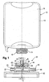
- the sealing apparatus has a pressure-tight container 10 of bottle-like shape made of plastic which is capable of being recycled. It includes a container wall 12 which surrounds a container inner space 18 in which the sealant is received.
- the container 10 has a somewhat cylindrical connection stub 16 which is formed in a manner of a bottle neck and which has an external thread 14 and forms the connection element of the container.
- connection possibilities such as for example an internal thread or latch devices or an internal thread recessed within the container.
- a removal unit 20 which is likewise manufactured generally or entirely of a plastic capable of being recycled includes a gas inlet 22 which has a cylindrical end section 24 projecting beyond the rest of the removal unit and which is surrounded by a wall 30.
- the upper end of the end section 24 of the gas inlet 22 at least partly has a reduced internal dimension, as will be explained with reference to Fig. 3 and Fig. 4 , but which is not however shown in Fig. 1 for the sake of clarity.
- the gas inlet 22 has an inlet tube 23 onto which a corresponding connection hose can be plugged.
- the removal unit 20 moreover has a tube stub 44 which has an internal thread 42. This inner thread 42 matches the outer thread 14 of the container 10. If the container 10 is screwed onto the removal unit 20 the end section 24 of the gas inlet 22 points into the container 10.
- valve seat 28 In the gas inlet 22, and in particular in the end section 24, there is a valve seat 28, with the gas inlet having a round cross-section in the region of the valve seat.
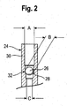
- the internal diameter of the end section 24 of the gas inlet 22 reduces conically in this region from a larger diameter A at the open end of the end section 24 of the gas inlet 22 to a small internal diameter C.
- the region of the smaller diameter C is accordingly located beneath the region of the larger diameter A.
- the valve seat 28 forms, in cooperation with a ball 26, a non-return valve 32.
- the ball 26 has an outer diameter B which is, on the one hand, smaller than the larger inner diameter A of the end section 24 of the gas inlet 22 and is, on the other hand, larger than the reduced diameter C of the gas inlet 22 beneath the valve seat 28.
- the tube stub 44 with the internal thread 42 surrounds the end section 24 of the gas inlet coaxially.
- the inner space of the tube stub 44 is part of the outlet 40 of the removal unit 20 which is connected to an outlet tube 46 onto which for example a hose can be plugged in order to connect the removal unit 20 to the valve of a tire to be sealed.
- a standing frame 50 is shown purely schematically in Fig. 1 to which the removal unit 20 is secured or which is included in the removal unit 20. This is for example a tripod or a quadripod which enables secure standing during the operation of the sealing apparatus.
- FIG. 2 the end section 24 of the housing 22 is shown once again in an enlarged detail.
- Fig. 2 shows the end section 24 in a stage shortly after the ball 26 has been introduced
- Fig. 3 and 4 each show an installation state following this of two different embodiments, respectively.
- the upper end of the gas inlet 22 which may be metallic, is pressed together for example by hand whereby the wall 30 has lost its cylindrical shape at the end without however being completely closed.
- the internal extent of the end section 24 of the gas inlet 22 has been reduced in one spatial direction to an internal measure D which is smaller than the outer diameter B of the ball 26.
- the ball 26 can accordingly no longer pass through the end of the end section 24 of the gas inlet 22.
- the internal diameter A of the end section 24 for example can be 4 mm and the diameter B of the ball 26 3.6 mm.
- the internal diameter C of the gas inlet 22 beneath the valve seat 28 then for example is 2.5 mm.
- the reduced internal dimension B in any case must be smaller than the diameter B of the ball 26, that is, smaller than 3.6 mm for the described dimensions.
- Fig. 4a shows another embodiment in a sectional view from the side and Fig. 4b shows a top view seen in the direction IV as indicated in Fig. 4a .
- the entire removing unit 20 is formed from a moulded plastic part and may be connected to a standing frame 50.
- the injection moulding process is carried out such that the end of the gas cylinder 24 still has the internal diameter A.
- the ball 26 is introduced through the opening in the end section 24 of the gas inlet and falls onto the valve seat 28.
- a hot embossing tool is used for forming the projecting lugs 52.
- This can for example be a hot embossing stamp with projections projecting downwardly or radially to the outside and which are disposed for example in the form of a star with an angle of 120 degrees between each other.
- the tool can be pressed into or on the end section 24 of the gas inlet 22.
- the heated projections the tool melts the edge of the opening of the end section 24 at the locations of the projections.
- the thus forming semi-fluid plastic of the end section of the gas inlet 22 moves a little downward and forms the projecting lugs 52 projecting at least also inwardly.
- the end section 24 projects beyond the rest of the removal unit so that the wall 30 of the end section 24 is easily accessible in order to bring about the indenting or the compression.
- the container 10 contains a liquid sealant.
- the removal unit 20 is placed with the aid of the standing frame 50 on the ground.
- a non-indicated filling line is plugged onto the outlet tube 46 and is connected at its other end to the valve of the tire to be sealed in a manner known per se. Any residual pressure which may still be present in the tire to be sealed can now escape through the filling line and the connection 40.
- connection stub 16 of the container 10 is screwed into the internal thread 42 and is thus positioned inverted. In doing so the end of the end section 24 of the gas inlet 22 penetrates a foil-like cover which is optionally provided at the connection stub 16 in order to provide access to the container 10.
- the removal unit is first screwed onto the container and the entire arrangement is then first brought into a position in which the container is inverted
- the ball 26 of the non-return valve 32 prevents the entry of sealant from the container 10 into the gas inlet 22 even when the container 10 is arranged inverted.
- a gas pressure source for example a small compressor, is connected to the inlet tube 23 of the gas inlet 22 in a manner known per se. Air is forced by this gas pressure source through the gas inlet 22. The ball 26 thus lifts out of the valve seat 28 and permits the pumping of air into the container 10.
- the sealant located in the container is pressed through the outlet 40 and the non-illustrated filling line into the tire to be sealed.
- the sealing apparatus of the invention When the required quantity of sealant has been introduced into the tire to repair the tire leak and when a residual quantity of sealant is present in the container 10 the sealing apparatus of the invention is turned through 180° and placed on the base of the container.
- the sealant now collects at the side of the container 10 remote from the removal unit 20 in the region of the base of the container so that the gas which still flows through the gas inlet 22 into the container flows directly into the outlet 40 and into the tire. In this manner the tire can be blown up to its operating pressure directly following the introduction of the sealant, or at least to a pressure at which the relevant vehicle can travel a certain distance.
- the special design and arrangement of the non-return valve 32 in the removing unit 20 enables the simple installation of the non-return valve.
- the ball 26 only simply has to be introduced through the opening into the end section 24 of the gas inlet 22 and for example the end of the end section 24 is squeezed together in one direction to a smaller diameter D ( Fig. 3 ) or the lugs 52 projecting inwardly are formed with a hot embossing process ( Fig. 4 ).
- the particular arrangement of the non-return valve 32 however in particular also ensures reliable operation. If residual pressure is still present in the tire during installation of the container 10 onto the removal unit 20, then this cannot lead to the sealant being pressed out of the container 10 through the gas inlet 22 in the direction of the compressor. This is prevented by the ball 26 which is pressed against the valve seat 28 by the elevated pressure from the tire acting through the container 10 and insofar prevents passage of the sealant in the direction of the compressor. During operation of the compressor, the ball 26 is lifted upwardly out of the valve seat 28 by the air flowing in from the compressor through the gas inlet 22. If the compressor is switched off during the operation then the ball 26 falls again in the direction of the valve seat 28, brought about solely by gravity, and closes the gas inlet 22. Sealant from the container 10 can thus not pass in the direction of the compressor even when this produces no pressure.
Landscapes
- Engineering & Computer Science (AREA)
- Mechanical Engineering (AREA)
Claims (15)
- Appareil pour sceller des articles gonflables, en particulier des pneumatiques, qui inclut les éléments suivants :- un conteneur étanche à la pression (10) pour recevoir un agent de scellement et ayant un élément de connexion (16),- une unité d'enlèvement (20) pour la connexion, de préférence pour une connexion vissée, avec l'élément de connexion (16) du conteneur (10),- une entrée de gaz (22) et une sortie (40) qui peuvent être couplées à l'article à sceller, l'entrée de gaz et la sortie étant agencées dans l'unité d'enlèvement (20) et communiquant via l'espace intérieur (18) du conteneur quand l'unité d'enlèvement (20) est connectée à l'élément de connexion (16) du conteneur, et- un clapet anti retour (32) qui est prévu dans l'entrée de gaz (22) de telle manière qu'il se ferme quand une pression élevée règne dans le conteneur (10) et possède un élément de fermeture (26), de préférence une bille qui est pressée de manière étanche par une pression élevée dans le conteneur (10) sur un siège de valve (28) dans l'entrée de gaz,
caractérisé en ce que- le clapet anti retour (32) est prévu dans une section terminale (24) de l'entrée de gaz (22) qui s'ouvre, sans être défléchie, vers le conteneur (10) quand l'unité d'enlèvement (20) est connectée au conteneur (10),- la section terminale (24) de l'entrée de gaz (22) se projette au-delà du reste de l'unité d'enlèvement, et- pour empêcher que l'élément de fermeture (26) s'échappe hors de la section terminale (24) de l'entrée de gaz (22), il est prévu une déformation de la paroi intérieure de la section terminale (24) de l'entrée de gaz, qui est dimensionnée de telle façon que l'élément de fermeture (26) ne peut pas la dépasser. - Appareil selon la revendication 1, caractérisé en ce que l'entrée de gaz (22) et la sortie (40) sont agencées coaxialement l'une par rapport à l'autre dans la région de la section terminale (24) de l'entrée de gaz (22), de sorte que la sortie (40) entoure l'entrée de gaz (22) dans cette région.
- Appareil selon l'une des revendications 1 ou 2, caractérisé en ce que- l'élément de fermeture inclut une bille (26),- la section terminale (24) de l'entrée de gaz (22) inclut un tube cylindrique (30), et- la déformation inclut une déviation de la section terminale (24) depuis une forme cylindrique, obtenue de préférence par pressage de la section terminale (24) sur elle-même.
- Appareil selon l'une des revendications 1 ou 2, caractérisé en ce que la section terminale (24) de l'entrée de gaz (22) comprend une pluralité, de préférence trois tétons en projection qui se projettent vers l'intérieur, qui sont d'une dimension telle est sont disposés de telle façon que la dimension interne libre de la section terminale (24) dans la région des tétons en projection (52) est plus petite que la dimension extérieure de l'élément de fermeture (26).
- Appareil selon l'une quelconque des revendications 1 à 4, caractérisé en ce que le clapet anti retour (32) est prévu dans une région de l'entrée de gaz (22) qui est alignée verticalement, et le siège de valve (28) est agencé au-dessous de l'élément de fermeture (26) quand l'unité d'enlèvement (22) est connectée à l'élément de connexion (16) du conteneur (10) et que le conteneur (10) est inversé.
- Appareil selon l'une quelconque des revendications 1 à 5, caractérisé en ce que l'entrée de gaz (22) peut être connectée en amont du clapet anti retour (32) à une source de gaz sous pression.
- Appareil selon l'une quelconque des revendications 1 à 6, caractérisé en ce que le conteneur (10) et/ou l'unité d'enlèvement (20) est/sont fabriqué(s) en matière plastique, laquelle est de préférence capable d'être recyclée.
- Unité d'enlèvement, en particulier pour un appareil selon l'une ou plusieurs des revendications précédentes, qui inclut les éléments suivants :- un dispositif de connexion (42), de préférence un pas de vis, pour la connexion à un élément de connexion (16) d'un conteneur étanche à la pression (10) pour la réception d'un agent de scellement,- une entrée de gaz (22) et une sortie (40) qui peut être couplée à un article à sceller, l'entrée de gaz et la sortie étant agencées dans l'unité d'enlèvement (20) et communiquant via l'espace intérieur (18) du conteneur quand l'unité d'enlèvement (20) est connectée à un élément de connexion (16) d'un conteneur (10), et- un clapet anti retour (32) qui est prévu dans l'entrée de gaz (22) de telle manière qu'il se ferme quand une pression élevée règne dans un conteneur attaché (10) et possède un élément de fermeture (26), de préférence une bille pressée de façon étanche dans un siège de valve (28) dans l'entrée de gaz (22) par une pression élevée dans le conteneur attaché (10),
caractérisée en ce que- le clapet anti retour (32) est prévu dans une section terminale (24) de l'entrée de gaz (22) qui s'ouvre vers le conteneur (10) sans être défléchie quand l'unité d'enlèvement (20) est connectée à un conteneur (10),- la section terminale (24) de l'entrée de gaz (22) se projette au-delà du reste de l'unité d'enlèvement, et- pour empêcher l'échappement de l'élément de fermeture (26) hors de la section terminale (24) de l'entrée de gaz (22), il est prévu une déformation de la paroi interne de la section terminale (24) de l'entrée de gaz (22), avec une dimension telle que l'élément de fermeture (26) ne peut pas la dépasser. - Unité d'enlèvement selon la revendication 8, caractérisée en ce que l'entrée de gaz (22) et la sortie (40) sont agencées coaxialement l'une à l'autre dans la région de la section terminale (34) de l'entrée de gaz (22), la sortie (40) entourant l'entrée de gaz (22) dans cette région.
- Unité d'enlèvement selon l'une des revendications 8 ou 9, caractérisée en ce que- l'élément de fermeture inclut une bille (16),- la section terminale (24) de l'entrée de gaz (22) inclut un tube cylindrique (30), et- la déformation inclut une déviation de la section terminale (24) depuis la forme cylindrique, qui est de préférence obtenue en pressant la section terminale (24) sur elle-même.
- Unité d'enlèvement selon l'une des revendications 8 ou 9, caractérisée en ce que la section terminale (24) de l'entrée de gaz (22) comprend une pluralité, de préférence trois tétons en projection qui se projettent vers l'intérieur, qui ont une dimension telle et qui sont disposés de telle façon que la dimension interne libre de la section terminale (24) dans la région des tétons en projection (52) est plus petite que la dimension extérieure de l'élément de fermeture (26).
- Unité d'enlèvement selon l'une quelconque des revendications 8 à 11, caractérisée en ce que le clapet anti retour (32) est prévu dans une région de l'entrée de gaz (22) qui est verticalement alignée et le siège de valve (28) est agencé au-dessous de l'élément de fermeture (26) quand l'unité d'enlèvement (20) est connectée à l'élément de connexion (16) d'un conteneur (10) et que le conteneur (10) est dressé tête en bas.
- Unité d'enlèvement selon l'une quelconque des revendications 8 à 12, caractérisée en ce que l'entrée de gaz (22) peut être connectée en amont du clapet anti retour (32) à une source de gaz sous pression.
- Unité d'enlèvement selon l'une quelconque des revendications 8 à 13, caractérisée en ce que l'unité d'enlèvement (20) est fabriquée en matière plastique, laquelle est de préférence capable d'être recyclée.
- Unité d'enlèvement selon l'une quelconque des revendications 8 à 14, caractérisée en ce que l'unité d'enlèvement (20) est réalisée d'une seule pièce à l'exception de l'élément de fermeture (26) du clapet anti retour (32).
Priority Applications (1)
| Application Number | Priority Date | Filing Date | Title |
|---|---|---|---|
| EP08002744.4A EP2090419B1 (fr) | 2008-02-14 | 2008-02-14 | Appareil d'obturation |
Applications Claiming Priority (1)
| Application Number | Priority Date | Filing Date | Title |
|---|---|---|---|
| EP08002744.4A EP2090419B1 (fr) | 2008-02-14 | 2008-02-14 | Appareil d'obturation |
Publications (2)
| Publication Number | Publication Date |
|---|---|
| EP2090419A1 EP2090419A1 (fr) | 2009-08-19 |
| EP2090419B1 true EP2090419B1 (fr) | 2013-12-25 |
Family
ID=39556174
Family Applications (1)
| Application Number | Title | Priority Date | Filing Date |
|---|---|---|---|
| EP08002744.4A Active EP2090419B1 (fr) | 2008-02-14 | 2008-02-14 | Appareil d'obturation |
Country Status (1)
| Country | Link |
|---|---|
| EP (1) | EP2090419B1 (fr) |
Families Citing this family (7)
| Publication number | Priority date | Publication date | Assignee | Title |
|---|---|---|---|---|
| WO2011109176A2 (fr) * | 2010-02-23 | 2011-09-09 | Itw Ccip Holdings Llc | Système et procédé de réparation de pneu |
| WO2011106271A2 (fr) * | 2010-02-23 | 2011-09-01 | Shell Oil Company | Appareil et procédé destiné à réparer un pneumatique |
| CN102791470B (zh) * | 2010-03-12 | 2014-11-12 | 住友橡胶工业株式会社 | 盖单元 |
| GB2482016A (en) * | 2010-07-16 | 2012-01-18 | David Leslie White | Device for dispensing liquids |
| DE102013223107A1 (de) * | 2013-11-13 | 2015-05-13 | Continental Reifen Deutschland Gmbh | Vorrichtung zum Abdichten und Aufpumpen aufblasbarer Gegenstände mit Lageventil |
| DE102018219038A1 (de) * | 2018-11-08 | 2020-05-14 | Continental Reifen Deutschland Gmbh | Verteilervorrichtung zur Erzeugung eines Aerosols, System zum Abdichten und Aufpumpen von Fahrzeugluftreifen und ein Verfahren zum Abdichten von Fahrzeugluftreifen oder aufblasbaren technischen Gummiartikeln sowie die Verwendung einer Dosiereinheit zum Erzeugen eines Aerosols |
| DE102021205682A1 (de) * | 2021-06-04 | 2022-12-08 | Continental Reifen Deutschland Gmbh | Dichtmittelvorrichtung zum Abdichten eines Fahrzeugreifens, Pannenhilfeset mit einer solchen Dichtmittelvorrichtung sowie ein Verfahren zur Herstellung einer solchen Dichtmittelvorrichtung |
Family Cites Families (6)
| Publication number | Priority date | Publication date | Assignee | Title |
|---|---|---|---|---|
| DE19652546B4 (de) | 1996-12-17 | 2012-11-22 | Sumitomo Rubber Industries Ltd. | Mittel zum Abdichten von Reifen bei Pannen, Vorrichtungen zum Abdichten und Aufpumpen von Reifen und Reifen mit integriertem Abdichtmittel |
| DE19846451C5 (de) | 1998-10-08 | 2018-08-23 | Sumitomo Rubber Industries Ltd. | Vorrichtung zum Abdichten aufblasbarer Gegenstände, insbesondere Reifen |
| PL202965B1 (pl) * | 2001-02-16 | 2009-08-31 | Continental Ag | Urządzenie do uszczelniania i napełniania obiektu nadmuchiwalnego oraz sposób uszczelniania i napełniania obiektu nadmuchiwalnego |
| WO2003004328A1 (fr) | 2001-07-02 | 2003-01-16 | Active Tools A/S | Unite de gonflage a dispositif d'etancheite pour un pneu rempli d'air |
| ITTO20040121A1 (it) * | 2004-02-27 | 2004-05-27 | Tek Srl | Contenitore per un liquido sigillante per la riparazione di oggetti gonfiabili, in particolare pnematici, e kit di riparazione provvisto di tale contenitore |
| ITTO20060662A1 (it) * | 2006-09-18 | 2008-03-19 | Tek Srl | Kit per la riparazione e il gonfiaggio di articoli gonfiabili |
-
2008
- 2008-02-14 EP EP08002744.4A patent/EP2090419B1/fr active Active
Also Published As
| Publication number | Publication date |
|---|---|
| EP2090419A1 (fr) | 2009-08-19 |
Similar Documents
| Publication | Publication Date | Title |
|---|---|---|
| EP2090419B1 (fr) | Appareil d'obturation | |
| CA2347421C (fr) | Dispositif d'etancheification | |
| CA2773255C (fr) | Dispositif de reparation de pneu contenant de la colle a caoutchouc | |
| KR100705370B1 (ko) | 키 코드 링을 구비한 액체 화학물 분배 시스템 | |
| US9199783B2 (en) | Plastic valves and methods of using the same | |
| AU782129B2 (en) | Sealing device | |
| US7878360B2 (en) | Container for sealant for pneumatic tires | |
| AU2007234616B2 (en) | Induction-sealable closure for liquid container | |
| US20150108175A1 (en) | Container with Pressure Relief Valve | |
| KR100561958B1 (ko) | 일체형 자동밀봉 밸브를 구비한 디스펜싱 클로우져 | |
| CN110325474B (zh) | 具有一体式通气系统的桶封闭件 | |
| EP2841375A2 (fr) | Conteneur muni d'une soupape de décharge de pression | |
| MX2008003465A (es) | Mejoras en el aparato de sellado. | |
| US10472142B2 (en) | Closure device for a container | |
| CN1315699C (zh) | 液体运输和存储用容器的塑料取出阀 | |
| KR101435996B1 (ko) | 용기의 부정사용 방지용 안전캡 | |
| JP2005319615A (ja) | タイヤパンク応急修理装置に用いるシーリング剤ユニット | |
| KR101324530B1 (ko) | 재활용 가능한 내부 확인 이중 구조 분사 용기 제조방법 | |
| KR20190086575A (ko) | 타이어 수리 장치 | |
| KR20160042919A (ko) | 팽창식 아티클 수리를 위한 일회용 실란트 액체 캐니스터 및 관련 제조 방법 | |
| US20210292080A1 (en) | Housing for a pressurised container | |
| CN105324328B (zh) | 用于具有气态介质供给可能性的饮料瓶的封帽 | |
| EP3061597B1 (fr) | Machine de réparation de pneu | |
| US10640361B1 (en) | Manual fluid extractor | |
| KR200280843Y1 (ko) | 부정주입 방지용 병마개 |
Legal Events
| Date | Code | Title | Description |
|---|---|---|---|
| PUAI | Public reference made under article 153(3) epc to a published international application that has entered the european phase |
Free format text: ORIGINAL CODE: 0009012 |
|
| AK | Designated contracting states |
Kind code of ref document: A1 Designated state(s): AT BE BG CH CY CZ DE DK EE ES FI FR GB GR HR HU IE IS IT LI LT LU LV MC MT NL NO PL PT RO SE SI SK TR |
|
| AX | Request for extension of the european patent |
Extension state: AL BA MK RS |
|
| 17P | Request for examination filed |
Effective date: 20090909 |
|
| 17Q | First examination report despatched |
Effective date: 20091113 |
|
| AKX | Designation fees paid |
Designated state(s): DE FR IT |
|
| GRAP | Despatch of communication of intention to grant a patent |
Free format text: ORIGINAL CODE: EPIDOSNIGR1 |
|
| INTG | Intention to grant announced |
Effective date: 20130716 |
|
| RIC1 | Information provided on ipc code assigned before grant |
Ipc: B29C 73/16 20060101AFI20130709BHEP |
|
| GRAS | Grant fee paid |
Free format text: ORIGINAL CODE: EPIDOSNIGR3 |
|
| GRAA | (expected) grant |
Free format text: ORIGINAL CODE: 0009210 |
|
| AK | Designated contracting states |
Kind code of ref document: B1 Designated state(s): DE FR IT |
|
| REG | Reference to a national code |
Ref country code: DE Ref legal event code: R096 Ref document number: 602008029473 Country of ref document: DE Effective date: 20140213 |
|
| REG | Reference to a national code |
Ref country code: DE Ref legal event code: R097 Ref document number: 602008029473 Country of ref document: DE |
|
| PLBE | No opposition filed within time limit |
Free format text: ORIGINAL CODE: 0009261 |
|
| STAA | Information on the status of an ep patent application or granted ep patent |
Free format text: STATUS: NO OPPOSITION FILED WITHIN TIME LIMIT |
|
| 26N | No opposition filed |
Effective date: 20140926 |
|
| REG | Reference to a national code |
Ref country code: DE Ref legal event code: R097 Ref document number: 602008029473 Country of ref document: DE Effective date: 20140926 |
|
| REG | Reference to a national code |
Ref country code: FR Ref legal event code: PLFP Year of fee payment: 9 |
|
| REG | Reference to a national code |
Ref country code: FR Ref legal event code: PLFP Year of fee payment: 10 |
|
| REG | Reference to a national code |
Ref country code: FR Ref legal event code: PLFP Year of fee payment: 11 |
|
| P01 | Opt-out of the competence of the unified patent court (upc) registered |
Effective date: 20230510 |
|
| PGFP | Annual fee paid to national office [announced via postgrant information from national office to epo] |
Ref country code: FR Payment date: 20251231 Year of fee payment: 19 |
|
| PGFP | Annual fee paid to national office [announced via postgrant information from national office to epo] |
Ref country code: DE Payment date: 20251230 Year of fee payment: 19 |
|
| PGFP | Annual fee paid to national office [announced via postgrant information from national office to epo] |
Ref country code: IT Payment date: 20260122 Year of fee payment: 19 |