EP2090504A2 - Cadre de bicyclette - Google Patents
Cadre de bicyclette Download PDFInfo
- Publication number
- EP2090504A2 EP2090504A2 EP09152553A EP09152553A EP2090504A2 EP 2090504 A2 EP2090504 A2 EP 2090504A2 EP 09152553 A EP09152553 A EP 09152553A EP 09152553 A EP09152553 A EP 09152553A EP 2090504 A2 EP2090504 A2 EP 2090504A2
- Authority
- EP
- European Patent Office
- Prior art keywords
- insert
- bicycle frame
- receptacle
- headset
- frame according
- Prior art date
- Legal status (The legal status is an assumption and is not a legal conclusion. Google has not performed a legal analysis and makes no representation as to the accuracy of the status listed.)
- Granted
Links
Images


Classifications
-
- B—PERFORMING OPERATIONS; TRANSPORTING
- B62—LAND VEHICLES FOR TRAVELLING OTHERWISE THAN ON RAILS
- B62K—CYCLES; CYCLE FRAMES; CYCLE STEERING DEVICES; RIDER-OPERATED TERMINAL CONTROLS SPECIALLY ADAPTED FOR CYCLES; CYCLE AXLE SUSPENSIONS; CYCLE SIDECARS, FORECARS, OR THE LIKE
- B62K21/00—Steering devices
- B62K21/06—Bearings specially adapted for steering heads
-
- B—PERFORMING OPERATIONS; TRANSPORTING
- B62—LAND VEHICLES FOR TRAVELLING OTHERWISE THAN ON RAILS
- B62K—CYCLES; CYCLE FRAMES; CYCLE STEERING DEVICES; RIDER-OPERATED TERMINAL CONTROLS SPECIALLY ADAPTED FOR CYCLES; CYCLE AXLE SUSPENSIONS; CYCLE SIDECARS, FORECARS, OR THE LIKE
- B62K19/00—Cycle frames
- B62K19/30—Frame parts shaped to receive other cycle parts or accessories
- B62K19/32—Steering heads
Definitions
- the invention relates to a bicycle frame with a head tube and a two headset bearing comprehensive tax rate for rotatably supporting a fork stem of a fork.
- the bicycle frame forms the skeleton of a bicycle and carries the weight of the rider and transfers this to the wheels. In addition, the bicycle frame carries all components and attachments. Due to the design and construction of the bicycle frame, the driving characteristics of the bicycle are significantly determined.
- the diamond frame which was developed as early as 1885, is the most common frame shape for bicycles. It consists essentially of a triangle, formed by the saddle struts, the chain stays and the seat tube and a trapeze that is formed by the top tube, the seat tube, the down tube and the head tube.
- the optimal size of the frame depends among other things on the height of the driver. The frame size is determined by the frame height and the frame length.
- the frame height is usually measured from the center of the bottom bracket to the top edge of the saddle sleeve.
- the frame length is usually measured horizontally from the center of the seat tube to the center of the head tube.
- the fine adjustment of the height is accomplished by adjusting the seat post. This will change the distance between the center of the bottom bracket and the top of the saddle. A fine adjustment of the distance between the saddle tip and the center of the handlebar in the stem can be achieved by replacing it.
- the present invention relates to all frame shapes having a head tube, in particular Diamond frames and their modifications as well as trapezoidal frames or Y-frames.
- the DE 23 52 321 A1 discloses a mechanism for adjusting the inclination angle of the control head of the front fork of a motorcycle.
- an eccentric bearing outer ring is used in each end of the steering head tube, whose eccentric seat receives a bearing for the steering shaft.
- the angle of the steering shaft is changed by disassembling the control head, removing the bearing outer rings and reinserting them about their longitudinal axis through 180 degrees.
- the bearing seat either has a spherical portion-shaped curved outer surface or the axis of the eccentric seat is at an angle to the axis of the steering head tube.
- the invention is based on the object to provide a bicycle frame of the type mentioned, which can be easily and inexpensively adapted to different sized driver and allows a change in driving characteristics of a bicycle equipped with this frame with simple means ,
- the object is achieved in that in the use position of the bicycle frame upper end side of the control tube releasably in the control tube form-fitting engaging insert is arranged on the in a use position of the bicycle frame lower end of the control tube releasably engaging in the control tube insert positively insert is arranged, the upper insert a receptacle for the upper Headset bearing of the headset and the lower insert has a receptacle for the lower headset bearing, the inserts are axisymmetric, the upper receptacle for the upper headset bearing and the lower receptacle for the lower headset bearing are arranged eccentric to the symmetry axis of the upper and lower insert and the eccentricity of the lower and upper receptacle coincides with the symmetry axis of the lower and upper insert.
- the releasable engaging in the upper and lower end face of the head tube inserts allow a rapid change in position of the defined by the upper and lower headset bearing axis of rotation of the steerer.
- the receptacle for the upper or lower headset bearing in the insert in the frame longitudinal direction is further forward or rear, the distance between the fork and thus the wheel hub receptacle to the bottom bracket can be changed quickly. As a result, not only the sitting position of the driver, but in particular the driving characteristics of the bicycle having the frame are changed.
- the axis-symmetrical inserts in particular in the form of an ellipse or super ellipse, can be displaced 180 degrees about the axis of symmetry into the receptacles for the upper headset bearing and for the lower headset bearing in the longitudinal direction of the bicycle frame, because the receptacles are eccentric to the axis of rotation of the upper and lower insert are arranged.
- the receptacles are eccentric to the axis of rotation of the upper and lower insert are arranged.
- the inserts can thus already two distances between Hubnabenability and adjust the bottom bracket shell.
- a larger distance between the wheel and the bottom bracket contributes to the use of the bike by a larger driver significantly to increase safety, because the risk of collisions of the toe with the front wheel when turning and thus the risk of falling can be reduced.
- the largest diameter of the receptacle is smaller than the longitudinal extension of the insert in the longitudinal direction of the frame to such an extent, so that the receptacle in the insert can be placed farther forward or rearward in the longitudinal direction of the frame.
- the edge on both sides of the receptacle in the longitudinal direction of the frame has an overall extension which is at least 20%, but preferably at least 30% -50%, of the largest diameter of the receptacle.
- a feather key between the insert and the head tube may be arranged;
- the positive connection is due to the shape of the insert to conditions, which coincides with the inner cross section of the head tube.
- Oval or elliptical disks are particularly suitable for this preferred embodiment of the insert.
- the disc-shaped inserts can also have the shape of a super ellipse.
- the superellipse is understood to mean a geometric figure which represents a middle point between an ellipse and a rectangle.
- the disc-shaped inserts may also have the shape of particular axisymmetric polygons, which engage positively in a correspondingly shaped control tube.
- a closer stepped adjustment of the distances between the bottom bracket and the wheel hub receptacle can be achieved if suitable for the bicycle frame several insert pairs consisting of a respective lower and an upper insert are manufactured, wherein the receptacles for the headset bearings in each pair are arranged at a different position.
- the recordings are arranged, for example, offset in 5 mm increments in the frame longitudinal direction.
- an axial symmetry of the preferably configured as a disc inserts is not mandatory.
- the contour of the discs may in this case, for example, have the shape of an arbitrary oval.
- the upper receptacle for the upper headset bearing and the lower receptacle for the lower headset bearing with respect to the built-in control tube upper and lower inserts are always arranged consistently; in the matching in the form inserts is thus ensured in the cylindrical head tube that by pairwise replacement of the inserts, the control axis is moved in parallel in the head tube.
- an upper support flange for the engaging in the head tube insert and spaced from the frontal lower opening a lower support flange arranged for engaging in the head tube insert As an abutment for the biasing force acting on the headset in the head tube at a distance from the frontal upper opening an upper support flange for the engaging in the head tube insert and spaced from the frontal lower opening a lower support flange arranged for engaging in the head tube insert.
- the distance between the front-side opening and the support flange corresponds at least to the thickness of the upper or lower disk, so that the serving as an insert disks are preferably flush with the frontal openings of the head tube. If the distance is slightly larger than the thickness of the disc, this is slightly sunk in the head tube, so that for aesthetic reasons, a cover plate can be mounted above the insert. Finally, the distance can be slightly less than the thickness of the disc at least at the top of the control tube, which then protrudes slightly beyond the head tube.
- the inserts can have a flange surrounding the insert on their side pointing in the installation position in the direction of the end opening of the head tube, or at least one projection arranged on the edge of each insert, which is supported on the opening edge of the head tube.
- the flange or projection preferably terminates flush with the surface of the insert.
- the tax rate includes two tax rate camps. Each headset bearing has an inner and outer ring and in between the rolling elements. In addition, there are so-called integrated tax rates, in which an encapsulated bearing is taken up by a bearing shell. These bearings form the running surface for the rolling elements of the encapsulated bearing. Both tax rate stock options are referred to collectively as tax rates.
- the upper receptacle for the associated headset bearing and the lower receptacle for the associated headset bearing are preferably designed as a conical seat.
- the tapered abutment surfaces for the headset bearing in the insert with preferably 36 degrees or 45 degrees are incorporated.
- the headset bearing can be installed without special tools and without pressing into the receptacle of the insert.
- the receptacles can be designed as cylindrical clamping seats for the bearing shells. Also cheaper tax rate, z. B. axial / angular contact ball bearings, are preferably pressed into hollow cylindrical receptacles in the inserts.
- Both the cylindrical clamping seat and the conical seat formed as a receptacle are designed as a passageway through the insert, the smallest diameter of which corresponds at least to the outer diameter of the male fork stem.
- the insert arranged on the upper end side of the control tube and the insert arranged on the lower end side of the control tube are interconnected by a preferably circular cylindrical hollow cylinder, through the hollow of which the steerer tube can be passed, this hollow cylinder absorbs the pretensioning force acting on the headset.
- Support flanges or protrusions on the inserts are basically dispensable in such an embodiment.
- the hollow cylinder may have a smaller cross section relative to the inserts, so that its outer wall has no contact with the control tube. It is also conceivable, however, a hollow cylinder with a cross section corresponding to the inner contour of the head tube.
- both inserts from one of the end faces of the control tube is possible, in which the unit is pushed from two inserts and hollow cylinder into the head tube.
- the length of the hollow cylinder is matched to the length of the head tube, so that the frontal openings of the receptacles for the headset stock with the openings of the head tube close in about flush.
- the two inserts and the hollow cylinder are integrally formed, for example as an injection-molded part. Regardless of the shape of the inserts, the upper headset bearing retainer and the lower headset bearing retainer each extend to the hollow cylinder to provide an unobstructed passage for the steerer tube.
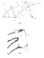
- FIG. 1 shows a designed as a diamond frame bicycle frame (1), which consists of a triangle formed by a seat post (2), a chain stay (3) and a seat tube (4) and a trapezoid through a top tube (5), the seat tube (4 ), a down tube (6) and a control tube (7) is formed.
- the control tube (7) forms the bearing housing for the headset (10) for rotatably supporting a steerer tube (8) of a fork (9) for guiding the front wheel, not shown, of a bicycle.
- the headset (10) comprises two steerings leading to the steerer tube (8), which are referred to in bicycles as headset bearings (11,12).
- a headset bearing (11,12) come in particular tapered roller bearings or conical needle roller bearings as well as for simple bearings axial / angular contact ball bearings into consideration.
- the inner ring of the lower headset bearing (12) is pressed onto the steerer tube (8) or fixed by a conical seat.
- the inner ring of the upper headset bearing (11) is screwed depending on the design of the steerer tube (8) or fixed in modern forks by a conical seat. If the Steerer (8) is unthreaded, belongs to the tax rate own, not shown in the figures jig.
- the attachment of the tensioning device is done by means of a claw or an expansion cone, which is taken or introduced into the steerer tube (8).
- a cap On the stem a cap is attached, which contains a screw with which the steerer is pulled upwards. As a result, a bias is exercised on the tax rate.
- control tube (7) In the control tube (7) is located at a distance from the front-side upper opening (16) has a circumferential in FIG. 4 illustrated upper support flange (18), for the in the control tube (7) engaging insert (13). At a distance from the lower opening (17) there is a further circumferential lower support flange (19) for the insert (14) engaging in the control tube (7) from below.
- the perpendicular to the axis of rotation (20) of the steerer tube (8) extending support portions of the upper and lower support flange (18,19) are located at a distance from the respective end upper or lower openings (16, 17), which is approximately the thickness the disc-shaped upper and lower insert (13,14) corresponds.
- the horizontal Sections extend only so far into the control tube (7), that the steerer tube (8) can be passed through the control tube (7) without difficulty, regardless of the insert (13, 14) used in each case.
- Both the upper insert (13) and the lower insert (14) each have a conical seat as a receptacle (21) for the upper headset bearing (11) and as a receptacle (22) for the lower headset bearing (12).
- the receptacles (21, 22) are arranged eccentrically to the axisymmetric inserts (13, 14). In this case, the eccentricity of the lower and upper receptacle coincides with the axis of symmetry of the inserts (13, 14).
- the stem which includes the fork stem (8) from the outside in today's forks, moves in the direction of the bottom bracket shell (24).
- the stem which includes the fork stem (8) from the outside in today's forks, moves in the direction of the bottom bracket shell (24).
- FIG. 3b It can be seen how the position of the axis of rotation (20) in the frame longitudinal direction (26) is displaced by removing, turning and reinserting the inserts (13, 14) in the control tube (7).
- FIG. 6 shows finally a variant of the bicycle frame (1) in which a at the upper end side of the control tube (7) arranged upper insert (27) and at the lower end side of the control tube (7) arranged lower insert (28) by a circular cylindrical hollow cylinder (29 ) are interconnected, through the cavity of the steerer tube (8) is passed.
- the two inserts (27,28) and the hollow cylinder (29) are integrally formed.
- the illustrated hollow cylinder (29) has a smaller cross-section relative to the inserts (27, 28), so that its outer wall (30) has no contact with the control tube (7).
- a hollow cylinder (29) having a cross-section corresponding to the inner contour of the control tube, the outer wall of which rests against the inner wall of the control tube (7).
- the Hollow cylinder (29) In the direction of the axis of rotation (20) extends the Hollow cylinder (29) to the passages (33,34) for the steerer tube (8) in the receptacles (31,32) zoom.
- the two interconnected inserts (27,28) are preferably pushed from the upper end side of the control tube (7) in the control tube (7).
- the length of the hollow cylinder (29) is matched to the length of the control tube (7), so that the frontal openings of the receptacles (31,32) for the headset bearing flush with the openings of the head tube.
Landscapes
- Engineering & Computer Science (AREA)
- Mechanical Engineering (AREA)
- Steering Devices For Bicycles And Motorcycles (AREA)
- Motorcycle And Bicycle Frame (AREA)
Applications Claiming Priority (1)
| Application Number | Priority Date | Filing Date | Title |
|---|---|---|---|
| DE200810009603 DE102008009603A1 (de) | 2008-02-15 | 2008-02-15 | Fahrradrahmen |
Publications (3)
| Publication Number | Publication Date |
|---|---|
| EP2090504A2 true EP2090504A2 (fr) | 2009-08-19 |
| EP2090504A3 EP2090504A3 (fr) | 2010-07-07 |
| EP2090504B1 EP2090504B1 (fr) | 2013-05-01 |
Family
ID=40445891
Family Applications (1)
| Application Number | Title | Priority Date | Filing Date |
|---|---|---|---|
| EP20090152553 Active EP2090504B1 (fr) | 2008-02-15 | 2009-02-11 | Cadre de bicyclette |
Country Status (2)
| Country | Link |
|---|---|
| EP (1) | EP2090504B1 (fr) |
| DE (1) | DE102008009603A1 (fr) |
Cited By (2)
| Publication number | Priority date | Publication date | Assignee | Title |
|---|---|---|---|---|
| ES2681999A1 (es) * | 2017-03-17 | 2018-09-17 | Universidad Carlos Iii De Madrid | Conjunto de excéntricas para apoyo regulable de ejes |
| US11780528B2 (en) * | 2020-05-21 | 2023-10-10 | Specialized Bicycle Components, Inc. | Adjustable head angle bicycles |
Families Citing this family (5)
| Publication number | Priority date | Publication date | Assignee | Title |
|---|---|---|---|---|
| DE102011086127A1 (de) * | 2011-11-10 | 2013-05-16 | Jochen Klieber | Fahrradsteuersatz mit Lenkwinkelverstellung |
| DE202020103230U1 (de) | 2020-06-05 | 2021-09-07 | Canyon Bicycles Gmbh | Lageraufnahmeelement sowie Fahrradelement |
| DE102020116139A1 (de) | 2020-06-18 | 2021-12-23 | Bayerische Motoren Werke Aktiengesellschaft | Vorderradführung für ein Neigefahrzeug sowie Neigefahrzeug |
| DE102021111451B3 (de) | 2021-05-04 | 2022-08-04 | Simon Schmitzer | Steuersatz für ein Fahrrad |
| DE102024104096B4 (de) * | 2024-02-14 | 2025-12-04 | MPR GmbH & Co. KG | Fahrradrahmen mit veränderbarer Rahmengeometrie |
Citations (2)
| Publication number | Priority date | Publication date | Assignee | Title |
|---|---|---|---|---|
| DE2352321A1 (de) | 1972-10-26 | 1974-05-09 | Bombardier Ltd | Mechanismus zum einstellen des neigungswinkels des steuerkopfes der vorderradgabel eines motorrads |
| EP0894701A2 (fr) | 1997-07-29 | 1999-02-03 | Cagiva Motor S.p.A. | Dispositif de verrouillage de forme conique pour support de palier de direction de véhicule à moteur |
Family Cites Families (6)
| Publication number | Priority date | Publication date | Assignee | Title |
|---|---|---|---|---|
| JPH03235775A (ja) * | 1990-02-09 | 1991-10-21 | Yamaha Motor Co Ltd | 自動二輪車のステアリング装置 |
| DE4137203C2 (de) * | 1991-11-12 | 1998-04-09 | Industrieanlagen Betriebsges | Nachlaufveränderndes Element für Motorräder |
| AT404460B (de) * | 1995-03-15 | 1998-11-25 | Rajek Josef Ing | Lagerung der lenkkopfachse in den gabelbrücken eines motorrad-lenkkopfes |
| IT1283734B1 (it) * | 1996-04-12 | 1998-04-30 | Ducati Motorcycles S P A | Dispositivo per modificare l'avancorsa di una motocicletta mediante variazione dell'avanzamento dell'asse di sterzo del veicolo |
| US5938225A (en) * | 1997-02-26 | 1999-08-17 | Harley-Davidson Motor Company | Motorcycle with enhanced steering assembly |
| JP4648529B2 (ja) * | 2000-09-21 | 2011-03-09 | 本田技研工業株式会社 | 車両 |
-
2008
- 2008-02-15 DE DE200810009603 patent/DE102008009603A1/de not_active Withdrawn
-
2009
- 2009-02-11 EP EP20090152553 patent/EP2090504B1/fr active Active
Patent Citations (2)
| Publication number | Priority date | Publication date | Assignee | Title |
|---|---|---|---|---|
| DE2352321A1 (de) | 1972-10-26 | 1974-05-09 | Bombardier Ltd | Mechanismus zum einstellen des neigungswinkels des steuerkopfes der vorderradgabel eines motorrads |
| EP0894701A2 (fr) | 1997-07-29 | 1999-02-03 | Cagiva Motor S.p.A. | Dispositif de verrouillage de forme conique pour support de palier de direction de véhicule à moteur |
Cited By (3)
| Publication number | Priority date | Publication date | Assignee | Title |
|---|---|---|---|---|
| ES2681999A1 (es) * | 2017-03-17 | 2018-09-17 | Universidad Carlos Iii De Madrid | Conjunto de excéntricas para apoyo regulable de ejes |
| US11780528B2 (en) * | 2020-05-21 | 2023-10-10 | Specialized Bicycle Components, Inc. | Adjustable head angle bicycles |
| US12065213B2 (en) | 2020-05-21 | 2024-08-20 | Specialized Bicycle Components, Inc. | Adjustable head angle bicycles |
Also Published As
| Publication number | Publication date |
|---|---|
| DE102008009603A1 (de) | 2009-09-03 |
| EP2090504B1 (fr) | 2013-05-01 |
| EP2090504A3 (fr) | 2010-07-07 |
Similar Documents
| Publication | Publication Date | Title |
|---|---|---|
| EP2090504B1 (fr) | Cadre de bicyclette | |
| EP2768714B1 (fr) | Unité palier d'arbre de direction | |
| EP0662419B1 (fr) | Bicyclette avec une fourche avant d'un matériel composite | |
| EP2885193B1 (fr) | Tube de guidage pour arbre de direction et son procédé de fabrication | |
| WO1988005394A1 (fr) | Bicyclette pliante | |
| DE102015016764A1 (de) | Fahrradgabelschaft mit variabler Steifigkeit | |
| WO2016110335A1 (fr) | Procédé de fabrication d'une colonne de direction modulaire munie de profilés extrudés | |
| WO2016110336A1 (fr) | Colonne de direction à palier pivotant adaptable | |
| EP2408659B1 (fr) | Potence de guidon pour bicyclette | |
| WO1996003307A1 (fr) | Fourche a ressort d'un palier de roue pour deux-roues | |
| EP1232929B1 (fr) | Colonne de direction de sécurité | |
| DE102019214557A1 (de) | Manteleinheit und Lenksäule für ein Kraftfahrzeug | |
| EP1257745A1 (fr) | Articulation de palier a roulement | |
| WO2023284989A1 (fr) | Procédé et dispositif de laminage par compression d'une roue de véhicule | |
| EP3572312B1 (fr) | Élément de centrage et dispositif de direction pour bicyclette | |
| DE102022121453B4 (de) | Lenkervorbau für ein Fahrrad und Fahrrad | |
| DE102006029781A1 (de) | Verfahren und Anordnung zur Befestigung eines Stoßdämpfers für ein Fahrrad | |
| EP3590802B1 (fr) | Vélo avec support de bicyclette et socle intégré au cadre | |
| EP3718872B1 (fr) | Véhicule, en particulier véhicule à deux roues et unité de potence de guidon | |
| DE102024104096B4 (de) | Fahrradrahmen mit veränderbarer Rahmengeometrie | |
| DE102019119565A1 (de) | Fahrzeug, insbesondere Zweiradfahrzeug, und Radgabel-Vorbau-Kombination | |
| DE102004024876A1 (de) | Lenksäulenanordnung mit einer in ihrer Neigung und Länge veränderbaren Lenksäule | |
| WO2012116955A1 (fr) | Tige de selle | |
| EP3620363B1 (fr) | Système de fourche | |
| DE4330464A1 (de) | Fahrradrahmen |
Legal Events
| Date | Code | Title | Description |
|---|---|---|---|
| PUAI | Public reference made under article 153(3) epc to a published international application that has entered the european phase |
Free format text: ORIGINAL CODE: 0009012 |
|
| AK | Designated contracting states |
Kind code of ref document: A2 Designated state(s): AT BE BG CH CY CZ DE DK EE ES FI FR GB GR HR HU IE IS IT LI LT LU LV MC MK MT NL NO PL PT RO SE SI SK TR |
|
| AX | Request for extension of the european patent |
Extension state: AL BA RS |
|
| PUAL | Search report despatched |
Free format text: ORIGINAL CODE: 0009013 |
|
| AK | Designated contracting states |
Kind code of ref document: A3 Designated state(s): AT BE BG CH CY CZ DE DK EE ES FI FR GB GR HR HU IE IS IT LI LT LU LV MC MK MT NL NO PL PT RO SE SI SK TR |
|
| AX | Request for extension of the european patent |
Extension state: AL BA RS |
|
| 17P | Request for examination filed |
Effective date: 20100913 |
|
| AKX | Designation fees paid |
Designated state(s): AT BE BG CH CY CZ DE DK EE ES FI FR GB GR HR HU IE IS IT LI LT LU LV MC MK MT NL NO PL PT RO SE SI SK TR |
|
| 17Q | First examination report despatched |
Effective date: 20111017 |
|
| GRAP | Despatch of communication of intention to grant a patent |
Free format text: ORIGINAL CODE: EPIDOSNIGR1 |
|
| GRAS | Grant fee paid |
Free format text: ORIGINAL CODE: EPIDOSNIGR3 |
|
| GRAA | (expected) grant |
Free format text: ORIGINAL CODE: 0009210 |
|
| AK | Designated contracting states |
Kind code of ref document: B1 Designated state(s): AT BE BG CH CY CZ DE DK EE ES FI FR GB GR HR HU IE IS IT LI LT LU LV MC MK MT NL NO PL PT RO SE SI SK TR |
|
| REG | Reference to a national code |
Ref country code: GB Ref legal event code: FG4D Free format text: NOT ENGLISH |
|
| REG | Reference to a national code |
Ref country code: AT Ref legal event code: REF Ref document number: 609745 Country of ref document: AT Kind code of ref document: T Effective date: 20130515 Ref country code: CH Ref legal event code: EP |
|
| REG | Reference to a national code |
Ref country code: IE Ref legal event code: FG4D Free format text: LANGUAGE OF EP DOCUMENT: GERMAN |
|
| REG | Reference to a national code |
Ref country code: CH Ref legal event code: NV Representative=s name: PATENTANWAELTE SCHAAD, BALASS, MENZL AND PARTN, CH |
|
| REG | Reference to a national code |
Ref country code: DE Ref legal event code: R096 Ref document number: 502009006983 Country of ref document: DE Effective date: 20130704 |
|
| REG | Reference to a national code |
Ref country code: NL Ref legal event code: VDEP Effective date: 20130501 |
|
| REG | Reference to a national code |
Ref country code: LT Ref legal event code: MG4D |
|
| PG25 | Lapsed in a contracting state [announced via postgrant information from national office to epo] |
Ref country code: ES Free format text: LAPSE BECAUSE OF FAILURE TO SUBMIT A TRANSLATION OF THE DESCRIPTION OR TO PAY THE FEE WITHIN THE PRESCRIBED TIME-LIMIT Effective date: 20130812 Ref country code: SE Free format text: LAPSE BECAUSE OF FAILURE TO SUBMIT A TRANSLATION OF THE DESCRIPTION OR TO PAY THE FEE WITHIN THE PRESCRIBED TIME-LIMIT Effective date: 20130501 Ref country code: PT Free format text: LAPSE BECAUSE OF FAILURE TO SUBMIT A TRANSLATION OF THE DESCRIPTION OR TO PAY THE FEE WITHIN THE PRESCRIBED TIME-LIMIT Effective date: 20130902 Ref country code: SI Free format text: LAPSE BECAUSE OF FAILURE TO SUBMIT A TRANSLATION OF THE DESCRIPTION OR TO PAY THE FEE WITHIN THE PRESCRIBED TIME-LIMIT Effective date: 20130501 Ref country code: NO Free format text: LAPSE BECAUSE OF FAILURE TO SUBMIT A TRANSLATION OF THE DESCRIPTION OR TO PAY THE FEE WITHIN THE PRESCRIBED TIME-LIMIT Effective date: 20130801 Ref country code: LT Free format text: LAPSE BECAUSE OF FAILURE TO SUBMIT A TRANSLATION OF THE DESCRIPTION OR TO PAY THE FEE WITHIN THE PRESCRIBED TIME-LIMIT Effective date: 20130501 Ref country code: FI Free format text: LAPSE BECAUSE OF FAILURE TO SUBMIT A TRANSLATION OF THE DESCRIPTION OR TO PAY THE FEE WITHIN THE PRESCRIBED TIME-LIMIT Effective date: 20130501 Ref country code: IS Free format text: LAPSE BECAUSE OF FAILURE TO SUBMIT A TRANSLATION OF THE DESCRIPTION OR TO PAY THE FEE WITHIN THE PRESCRIBED TIME-LIMIT Effective date: 20130901 Ref country code: GR Free format text: LAPSE BECAUSE OF FAILURE TO SUBMIT A TRANSLATION OF THE DESCRIPTION OR TO PAY THE FEE WITHIN THE PRESCRIBED TIME-LIMIT Effective date: 20130802 |
|
| PG25 | Lapsed in a contracting state [announced via postgrant information from national office to epo] |
Ref country code: HR Free format text: LAPSE BECAUSE OF FAILURE TO SUBMIT A TRANSLATION OF THE DESCRIPTION OR TO PAY THE FEE WITHIN THE PRESCRIBED TIME-LIMIT Effective date: 20130501 Ref country code: BG Free format text: LAPSE BECAUSE OF FAILURE TO SUBMIT A TRANSLATION OF THE DESCRIPTION OR TO PAY THE FEE WITHIN THE PRESCRIBED TIME-LIMIT Effective date: 20130801 Ref country code: PL Free format text: LAPSE BECAUSE OF FAILURE TO SUBMIT A TRANSLATION OF THE DESCRIPTION OR TO PAY THE FEE WITHIN THE PRESCRIBED TIME-LIMIT Effective date: 20130501 Ref country code: CY Free format text: LAPSE BECAUSE OF FAILURE TO SUBMIT A TRANSLATION OF THE DESCRIPTION OR TO PAY THE FEE WITHIN THE PRESCRIBED TIME-LIMIT Effective date: 20130501 |
|
| PG25 | Lapsed in a contracting state [announced via postgrant information from national office to epo] |
Ref country code: LV Free format text: LAPSE BECAUSE OF FAILURE TO SUBMIT A TRANSLATION OF THE DESCRIPTION OR TO PAY THE FEE WITHIN THE PRESCRIBED TIME-LIMIT Effective date: 20130501 |
|
| PG25 | Lapsed in a contracting state [announced via postgrant information from national office to epo] |
Ref country code: SK Free format text: LAPSE BECAUSE OF FAILURE TO SUBMIT A TRANSLATION OF THE DESCRIPTION OR TO PAY THE FEE WITHIN THE PRESCRIBED TIME-LIMIT Effective date: 20130501 Ref country code: CZ Free format text: LAPSE BECAUSE OF FAILURE TO SUBMIT A TRANSLATION OF THE DESCRIPTION OR TO PAY THE FEE WITHIN THE PRESCRIBED TIME-LIMIT Effective date: 20130501 Ref country code: DK Free format text: LAPSE BECAUSE OF FAILURE TO SUBMIT A TRANSLATION OF THE DESCRIPTION OR TO PAY THE FEE WITHIN THE PRESCRIBED TIME-LIMIT Effective date: 20130501 Ref country code: EE Free format text: LAPSE BECAUSE OF FAILURE TO SUBMIT A TRANSLATION OF THE DESCRIPTION OR TO PAY THE FEE WITHIN THE PRESCRIBED TIME-LIMIT Effective date: 20130501 |
|
| PG25 | Lapsed in a contracting state [announced via postgrant information from national office to epo] |
Ref country code: NL Free format text: LAPSE BECAUSE OF FAILURE TO SUBMIT A TRANSLATION OF THE DESCRIPTION OR TO PAY THE FEE WITHIN THE PRESCRIBED TIME-LIMIT Effective date: 20130501 Ref country code: RO Free format text: LAPSE BECAUSE OF FAILURE TO SUBMIT A TRANSLATION OF THE DESCRIPTION OR TO PAY THE FEE WITHIN THE PRESCRIBED TIME-LIMIT Effective date: 20130501 |
|
| PLBE | No opposition filed within time limit |
Free format text: ORIGINAL CODE: 0009261 |
|
| STAA | Information on the status of an ep patent application or granted ep patent |
Free format text: STATUS: NO OPPOSITION FILED WITHIN TIME LIMIT |
|
| 26N | No opposition filed |
Effective date: 20140204 |
|
| REG | Reference to a national code |
Ref country code: DE Ref legal event code: R097 Ref document number: 502009006983 Country of ref document: DE Effective date: 20140204 |
|
| BERE | Be: lapsed |
Owner name: MUFF, ANDRE ARMANDO Effective date: 20140228 |
|
| PG25 | Lapsed in a contracting state [announced via postgrant information from national office to epo] |
Ref country code: LU Free format text: LAPSE BECAUSE OF FAILURE TO SUBMIT A TRANSLATION OF THE DESCRIPTION OR TO PAY THE FEE WITHIN THE PRESCRIBED TIME-LIMIT Effective date: 20140211 Ref country code: MC Free format text: LAPSE BECAUSE OF FAILURE TO SUBMIT A TRANSLATION OF THE DESCRIPTION OR TO PAY THE FEE WITHIN THE PRESCRIBED TIME-LIMIT Effective date: 20130501 |
|
| GBPC | Gb: european patent ceased through non-payment of renewal fee |
Effective date: 20140211 |
|
| REG | Reference to a national code |
Ref country code: FR Ref legal event code: ST Effective date: 20141031 |
|
| REG | Reference to a national code |
Ref country code: IE Ref legal event code: MM4A |
|
| PG25 | Lapsed in a contracting state [announced via postgrant information from national office to epo] |
Ref country code: FR Free format text: LAPSE BECAUSE OF NON-PAYMENT OF DUE FEES Effective date: 20140228 Ref country code: IE Free format text: LAPSE BECAUSE OF NON-PAYMENT OF DUE FEES Effective date: 20140211 Ref country code: BE Free format text: LAPSE BECAUSE OF NON-PAYMENT OF DUE FEES Effective date: 20140228 Ref country code: GB Free format text: LAPSE BECAUSE OF NON-PAYMENT OF DUE FEES Effective date: 20140211 |
|
| REG | Reference to a national code |
Ref country code: AT Ref legal event code: MM01 Ref document number: 609745 Country of ref document: AT Kind code of ref document: T Effective date: 20140211 |
|
| PG25 | Lapsed in a contracting state [announced via postgrant information from national office to epo] |
Ref country code: AT Free format text: LAPSE BECAUSE OF NON-PAYMENT OF DUE FEES Effective date: 20140211 |
|
| PG25 | Lapsed in a contracting state [announced via postgrant information from national office to epo] |
Ref country code: MT Free format text: LAPSE BECAUSE OF FAILURE TO SUBMIT A TRANSLATION OF THE DESCRIPTION OR TO PAY THE FEE WITHIN THE PRESCRIBED TIME-LIMIT Effective date: 20130501 |
|
| PGFP | Annual fee paid to national office [announced via postgrant information from national office to epo] |
Ref country code: CH Payment date: 20160222 Year of fee payment: 8 |
|
| PG25 | Lapsed in a contracting state [announced via postgrant information from national office to epo] |
Ref country code: HU Free format text: LAPSE BECAUSE OF FAILURE TO SUBMIT A TRANSLATION OF THE DESCRIPTION OR TO PAY THE FEE WITHIN THE PRESCRIBED TIME-LIMIT; INVALID AB INITIO Effective date: 20090211 Ref country code: TR Free format text: LAPSE BECAUSE OF FAILURE TO SUBMIT A TRANSLATION OF THE DESCRIPTION OR TO PAY THE FEE WITHIN THE PRESCRIBED TIME-LIMIT Effective date: 20130501 |
|
| PGFP | Annual fee paid to national office [announced via postgrant information from national office to epo] |
Ref country code: IT Payment date: 20170217 Year of fee payment: 9 |
|
| REG | Reference to a national code |
Ref country code: CH Ref legal event code: PL |
|
| PG25 | Lapsed in a contracting state [announced via postgrant information from national office to epo] |
Ref country code: LI Free format text: LAPSE BECAUSE OF NON-PAYMENT OF DUE FEES Effective date: 20170228 Ref country code: CH Free format text: LAPSE BECAUSE OF NON-PAYMENT OF DUE FEES Effective date: 20170228 |
|
| PG25 | Lapsed in a contracting state [announced via postgrant information from national office to epo] |
Ref country code: MK Free format text: LAPSE BECAUSE OF FAILURE TO SUBMIT A TRANSLATION OF THE DESCRIPTION OR TO PAY THE FEE WITHIN THE PRESCRIBED TIME-LIMIT Effective date: 20130501 |
|
| PG25 | Lapsed in a contracting state [announced via postgrant information from national office to epo] |
Ref country code: IT Free format text: LAPSE BECAUSE OF NON-PAYMENT OF DUE FEES Effective date: 20180211 |
|
| REG | Reference to a national code |
Ref country code: DE Ref legal event code: R081 Ref document number: 502009006983 Country of ref document: DE Owner name: MUFF, ANDRE ARMANDO, CH Free format text: FORMER OWNER: MUFF, ANDRE ARMANDO, ZUERICH, CH |
|
| PGFP | Annual fee paid to national office [announced via postgrant information from national office to epo] |
Ref country code: DE Payment date: 20251121 Year of fee payment: 18 |