EP3590802B1 - Vélo avec support de bicyclette et socle intégré au cadre - Google Patents
Vélo avec support de bicyclette et socle intégré au cadre Download PDFInfo
- Publication number
- EP3590802B1 EP3590802B1 EP19184367.1A EP19184367A EP3590802B1 EP 3590802 B1 EP3590802 B1 EP 3590802B1 EP 19184367 A EP19184367 A EP 19184367A EP 3590802 B1 EP3590802 B1 EP 3590802B1
- Authority
- EP
- European Patent Office
- Prior art keywords
- bicycle frame
- incorporates
- accordance
- bicycle
- guide contour
- Prior art date
- Legal status (The legal status is an assumption and is not a legal conclusion. Google has not performed a legal analysis and makes no representation as to the accuracy of the status listed.)
- Active
Links
Images


Classifications
-
- B—PERFORMING OPERATIONS; TRANSPORTING
- B62—LAND VEHICLES FOR TRAVELLING OTHERWISE THAN ON RAILS
- B62H—CYCLE STANDS; SUPPORTS OR HOLDERS FOR PARKING OR STORING CYCLES; APPLIANCES PREVENTING OR INDICATING UNAUTHORIZED USE OR THEFT OF CYCLES; LOCKS INTEGRAL WITH CYCLES; DEVICES FOR LEARNING TO RIDE CYCLES
- B62H1/00—Supports or stands forming part of or attached to cycles
- B62H1/02—Articulated stands, e.g. in the shape of hinged arms
-
- B—PERFORMING OPERATIONS; TRANSPORTING
- B62—LAND VEHICLES FOR TRAVELLING OTHERWISE THAN ON RAILS
- B62K—CYCLES; CYCLE FRAMES; CYCLE STEERING DEVICES; RIDER-OPERATED TERMINAL CONTROLS SPECIALLY ADAPTED FOR CYCLES; CYCLE AXLE SUSPENSIONS; CYCLE SIDECARS, FORECARS, OR THE LIKE
- B62K19/00—Cycle frames
- B62K19/30—Frame parts shaped to receive other cycle parts or accessories
- B62K19/40—Frame parts shaped to receive other cycle parts or accessories for attaching accessories, e.g. article carriers, lamps
Definitions
- the invention relates to a bicycle frame according to the preamble of claim 1.
- a bicycle frame which constitutes the closest prior art.
- Two mutually oblique, straight surfaces of a base provided on the bicycle frame form contact surfaces against which a spring-loaded pressure piece of a support of the bicycle stand rests in either the standing position or the driving position of the support.
- the invention has for its object to improve a generic bicycle frame to the effect that this one supports the most economical production of the bicycle.
- the invention proposes that the base be designed as part of a rear-end dropout of the bicycle frame, which is simply referred to as a dropout.
- the bicycle frame is typically made from a plurality of tubes, but the dropouts are typically manufactured as sheet metal blanks from sheet material, such as by stamping, milling, or laser cutting operations.
- the guide contour can therefore be implemented in the base without having to create an additional component. This is not only advantageous in terms of the number of different parts, but also requires no additional assembly step. Rather, during the manufacture of the bicycle frame, the base of the bicycle stand is also installed at the same time as the dropout must be installed anyway.
- a further advantageous effect is that on bicycles on which no bicycle stand is to be mounted, the integration of the base into the dropout creates hardly any disruptive protrusions, compared to a base which is arranged on a chainstay of the bicycle frame, for example.
- this relates to the aesthetic effect that the unused base can have as a projection or overhang, which may be perceived as disturbing, but on the other hand also to the fact that body parts, clothing or the like can get caught on the unused projection.
- the base is shifted as far away as possible, for example from the circle on which the pedals are moved, and thus as far away as possible from the feet, shoelaces and trouser legs of a person using the bicycle.
- the dropout can advantageously consist of an angled plate material. This creates a first section of the dropout, which can be aligned exactly vertically, for example, and is used to hold the rear axle. A second section, which is angled in contrast, can be angled downwards and obliquely outwards and can have the guide contour. The angling causes the support to be spread outwards during its pivoting movement from the riding position to the standing position and thus, together with the two wheels, creates the largest possible footprint for the bicycle, defined by three contact points, which has a positive effect on the stability of the bicycle .
- Both troughs are each delimited by two edges running conically towards one another.
- the edge that is closer to the other trough in the course of the guide contour is referred to as the inner edge, and the other edge of a trough that is accordingly located at one end of the guide contour is referred to as the outer edge.
- the two outer edges each form a stop that limits the pivoting movement of the support.
- a clearly defined position of the support in its respective end position is achieved in that the stop runs essentially parallel to the direction of movement of the pressure piece, that is to say essentially transversely to the curved pivoting direction of the support.
- the pressure piece fills the respective trough in such a way that it rests against the two edges of the trough. Since the two edges of a trough run conically towards one another, the pressure piece, supported by the spring force, is always pressed as far as possible into the trough and into its correspondingly conical seat, so that it is held in the trough without play. As a result, the support is held in its respective end position without play. For the standing position, this means a particularly high level of stability of the bicycle, and for the driving position, this means a rattle-free mounting of the support even when driving over uneven ground.
- the direction of movement of the pressure piece can be offset relative to the pivot axis.
- the extension of the movement path, on which the central axis of the pressure piece is supported by spring force or runs counter to the direction of the spring, does not cross the pivot axis, but runs past the pivot axis.
- this offset is advantageously realized in such a way that the direction of movement of the pressure piece is offset downwards relative to the pivot axis when the support is in its driving position, this has an advantageous effect on the design degrees of freedom, since there is a larger one in the area of the rear wheel hub Space for drive or brake components is available, for example for electrical actuation of a gear shift.
- the strut can be broken down into three sections: a foot that supports it on the ground, a leg that makes up most of the length of the strut, and a head that connects the strut to the base, and with which it is pivotally mounted on the pivot axis.
- the base can advantageously be designed as a sheet metal blank and be encompassed by a head of the support, in that the head has a central recess and accordingly extends fork-like on both sides of the base.
- the base is configured as narrow and unobtrusively as possible in the event that the bicycle is not to be equipped with a bicycle stand and accordingly no support is mounted on the base.
- the spring acting on the pressure piece can be designed as an internal spring, so that it is optimally protected against external influences and any functional impairments associated therewith.
- the spring can advantageously be arranged in the head of the support, because while the leg is often designed as a tubular section, the head of a bicycle stand is often made as a separately manufactured die-cast or injection-molded component, so that there is no problem in creating areas in such a component , on which the spring is guided or supported.
- the spring acting on the pressure piece can advantageously be designed as a helical spring. Its longitudinal axis or central axis determines the direction of action of the spring and thus defines the direction of movement of the pressure piece.
- the configuration as a helical spring enables simple integration into the elongated shape of a support.
- the pressure piece can advantageously have a roof-shaped tip, with which it bears against the guide contour along the pivoting movement of the support. Even if the roof-shaped tip is preferably strongly rounded, there is a comparatively small contact surface between the pressure piece and the guide contour and thus low resistance and correspondingly low expenditure of force in order to be able to pivot the support between its two end positions relative to the base.
- the pressure piece has two abutment surfaces, one of which abuts against a stop when the support is in its two end positions.
- a comparatively large contact surface of the stop surfaces with the guide contour, namely with their respective stop, is made possible, so that the support can be reliably fixed and held in its respective end position.
- the dropout can have two parts, one of which has the guide contour.
- the dropouts usually have a number of connection points, which can be designed as through-holes, for example. Accordingly, the part having the guide contour can be designed in such a way that it can be connected to such connection points.
- a dropout can be modularly assembled from different components: one basic element of the dropout is always the same. On the one hand it connects to the seat and chainstays and on the other hand it has a mount for the rear axle. For bicycles that do not have a bicycle stand, a rear wheel mudguard or a rear wheel luggage rack, for example, this basic element can form the sole component of the dropout.
- the dropout is combined with a second part, for example welded, with this second part being able to have the connection points for a mudguard and/or a luggage rack and/or the guide contour of the proposed bicycle stand.
- FIG. 1 shows a perspective view of a bicycle stand 1.
- This has a base 2, indicated purely schematically, which is designed as an integral part of a bicycle frame, namely as an area of a dropout.
- the base 2 is part of a plate that is designed as a dropout of the bicycle frame. This plate is manufactured as a stamped part or as a laser cut from sheet metal with the usual sheet metal thickness for a dropout.
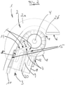
- the 2 and 3 show that the plate or the dropout has a first portion 2a, which is in a first, upright Level runs, namely in the illustrated embodiment in an exactly vertical plane.
- the opposite second dropout on the bicycle frame is also aligned vertically parallel thereto, and the rear axle of the bicycle is held in the vertical section 2a and the opposite dropout.
- the dropout has a second section 2b which runs in a second plane which is angled obliquely downwards and outwards to the first, perpendicular plane. This ensures that a foot 16 of the bicycle stand 1 in the standing position stands up on the ground to the side next to the bicycle frame and thus gives the bicycle a secure footing.
- the base 2 can have a contact surface with which it can be welded to a bicycle frame, for example to a chain stay.
- the curved shape on the upper edge of the base 2 is a purely schematically indicated delimitation of the vertical section 2a and in the illustrated embodiment is representative of the mentioned and also other conceivable configurations of the base 2.
- a support 3 of the bicycle stand 1 is movably mounted about a pivot axis 4 .
- the support 3 is designed to be telescopic so that it can be adapted to different bicycle frames.
- the standing position that can be seen represents a front end position of the support 3 in which the support 3 rests against a front stop 5 of the base 2 . From this front end position, the support 3 can be pivoted backwards about the pivot axis 4 until it assumes a horizontal driving position and in so doing rests against a rear stop 6 of the base 3 .
- a pressure piece 7 of the support 3 runs along a guide contour 8 of the base 2, the guide contour having the two stops 5 and 6 at its two ends.
- the support 3 has a head 18 at its upper end near the pivot axis 4, which grips the base 2, which is formed from a plate, like a fork on both sides and also encloses the pivot axis 4 in a ring on both of these sides .
- the pressure piece 7 is arranged in the head 18 and is pressed by a schematically indicated helical spring 9 in the direction of the pivot axis 4 and thus to bear against the guide contour 8 .
- the line of action of the helical spring 9 i.e. its imaginary central axis, does not run radially towards the pivot axis 4, but at a distance past the pivot axis 4, namely in front of the pivot axis 4 in the direction of travel of the bicycle.
- the pressure piece 7 To rest against the guide contour 8, the pressure piece 7 has a strongly rounded tip 19 with two flanks 11, which are arranged approximately A-shaped and are at an angle of approximately 90° to one another in the exemplary embodiment shown. Below the crest 19, ie closer to the foot 16 of the support 3, the pressure piece 7 has two outer stop surfaces 12 which abut the two stops 5 and 6 in the two end positions of the support 3. To guide the helical spring 9 , the pressure piece 7 has a mandrel 20 , the helical spring 9 being supported with its lower end, ie the end remote from the pivot axis 4 , on the head 18 or within the leg 10 .
- the pressure piece 7 dips into a trough, referred to as a standing trough 14 , in the guide contour 8 , the standing trough 14 being delimited by two contact surfaces 15 and extending between these two contact surfaces 15 .
- One contact surface 15 is formed by the front stop 5; a stop surface 12 of the pressure piece 7 rests on it.
- the other contact surface 15 is the edge 11 of the pressure piece 7 shown on the right, while a gap remains between the edge 11 shown on the left and the guide contour 8 within the trough 14 standing.
- the standing trough 14 is delimited by two conically running edges.
- the stop 5 represents an outer edge of the standing trough 14 because it forms one end of the entire guide contour 8, while the other contact surface 15 shown on the right is referred to as the inner edge. If wear occurs on the pressure piece 7 and/or on the guide contour 8, or if there are manufacturing tolerances, the helical spring 9 ensures that the pressure piece 7 is always pressed as far as possible and accordingly free of play into this conical seat, which the recess 14 creates for the pressure piece 7 .
- the stop 5 runs in the direction of movement of the pressure piece 7, so that the pressure piece 7 can slide along the stop 5, depending on wear or tolerance, until the right flank 11 of the pressure piece 7 touches the right contact surface 15 of the guide contour 8 is present.
- the stop 5 runs essentially parallel to the longitudinal axis of the support 3 or to the longitudinal axis of the helical spring 9.
- the stop 5 thus runs essentially transversely to the direction of movement, along which the support 3 can be moved about the pivot axis 4.
- the stop 5 therefore represents an effective limitation of the mobility of the support 3 and gives the bicycle parked by means of the bicycle stand 1 a high level of stability.
- the standing position shown represents one of the two end positions of the support 3. From the standing position, the support 3 can be pivoted counterclockwise about the pivot axis 4. Here, the pressure piece 7 follows with its tip 19 of the guide contour 8. Since the guide contour 8 following the stand trough 14 in an increasing Distance from the pivot axis 4 runs, the pressure piece 7 must be pressed against the action of the helical spring 9 in the direction of the foot 16 of the support 3 in order to be able to follow the guide contour 8 .
- the resistance thus created which tends to hinder the pivoting movement of the support 3, can be easily overcome by the user of the bicycle, but on the other hand ensures that the bicycle is stable even if the bicycle has been parked, for example, on a sloping surface in the direction of travel downhill is.
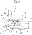
- the pressure piece 7 arrives along the guide contour 8 in a second trough, as shown in FIG 3 can be seen, this second trough being referred to as a driving trough 17 .
- This position of the support 3 is referred to as its driving position.
- the cradle 17 also has two contact surfaces 15 which each form an inner edge or outer edge delimiting the cradle 17 .
- the outer edge is created by the stop 6.
- the pressure piece 7 rests against this stop 6 with a stop surface 12, and similar to the standing trough 14, the stop 6 here also runs essentially parallel to the longitudinal axis of the support 3 or to the longitudinal axis of the helical spring 9, and in particular essentially transversely to the direction of movement. along which the support 3 has been pivoted about the pivot axis 4 into the trough 17 .
- FIG. 4 shows a side view of the pressure piece 7.
- the mandrel 20 extends much further down, i.e. away from the tip 19, than the two stop surfaces 12, so that a correspondingly long helical spring 9 can be used, which is, for example, significantly longer than schematic in 2 implied.
- figure 5 shows a view from below of the pressure piece 7. It is particularly clear that the two stop surfaces 12 grooves 21 connect. These cooperate with complementary ribs within the head 18 to To lead pressure piece 7 during movements along its direction of movement.
- the Figures 4 and 5 a safety lug 22, which projects laterally outwards on the pressure piece 7.
- the securing lug 22 limits how far the pressure piece 7 can be removed from the foot 16 of the support 3 by the helical spring 9 .
- a projection is provided inside the head 18, which limits this movement in that the securing lug 22 comes to rest on the projection. If, for example, the support 3 is removed from the base 2, the safety lug 22 prevents the pressure piece 7 from being shot out of the head 18 of the support 3 in an uncontrolled manner due to the spring effect.
Landscapes
- Engineering & Computer Science (AREA)
- Mechanical Engineering (AREA)
- Fittings On The Vehicle Exterior For Carrying Loads, And Devices For Holding Or Mounting Articles (AREA)
Claims (11)
- Cadre de bicyclette comprenant un support (1) de bicyclette,un premier élément du support (1) de bicyclette appelé socle (2), qui est configuré comme partie intégrante d'un cadre de bicyclette,et comprenant un deuxième élément du support (1) de bicyclette ayant la forme d'une béquille (3) maintenue contre le socle (2) tout en pouvant pivoter, béquille qui est déplaçable autour d'un axe de pivotement (4) entre deux positions finales appelées position d'arrêt et position de conduite, sachant que le deuxième élément présente une pièce de compression (7), avec laquelle il applique sous contrainte ressort contre un contour de guidage (8) du premier élément, et applique pendant le mouvement de pivotement en différents endroits du contour de guidage (8), caractérisé en ce que le socle (2) est configuré comme faisant partie d'une extrémité de fourche.
- Cadre de bicyclette selon la revendication 1, caractérisé en ce que le contour de guidage (8) présente deux creux qui définissent les deux positions finales, que les creux sont limités, le long du contour de guidage (8), par deux bords intérieurs réciproquement voisins présentant un tracé respectivement conique en direction l'un de l'autre, ainsi que par deux bords extérieurs, de sorte que chaque bord extérieur respectif forme une butée (5, 6) bloquant un mouvement pivotant de la béquille (3) au-delà de la position finale respective, sachant que le bord extérieur présente un tracé essentiellement parallèle à la direction du mouvement de la pièce de compression (7), et que la pièce de compression (7) est configurée pour remplir les creux de façon à ce que sous la contrainte ressort elle soit poussée sans jeu dans le siège conique du creux respectif.
- Cadre de bicyclette la revendication 1 ou 2, caractérisé en ce que la direction du mouvement de la pièce de compression (7) présente un tracé décalé par rapport à l'axe de pivotement (4).
- Cadre de bicyclette la revendication 3, caractérisé en ce que la direction du mouvement de la pièce de compression (7) est décalée vers le bas par rapport à l'axe de pivotement (4) lorsque la béquille (3) se trouve en position de conduite.
- Cadre de bicyclette selon l'une des revendications précédentes, caractérisé en ce qu'un premier segment (2a) de l'extrémité de fourche présente un tracé situé dans un premier plan redressé et qu'un deuxième segment (2b) de l'extrémité de fourche présente le contour de guidage et présente un tracé sur un deuxième plan formant un angle d'inclinaison par rapport au premier plan.
- Cadre de bicyclette selon l'une des revendications précédentes, caractérisé en ce que le socle (2) est configuré en forme de tôle découpée au format et que la béquille (3) présente une tête (18) s'étendant jusqu'à l'axe de pivotement (4) et entourant le socle (2) des deux côtés comme une fourche.
- Cadre de bicyclette selon l'une des revendications précédentes, caractérisé en ce que la béquille (3) présente une tête (18) s'étendant jusqu'à l'axe de pivotement (4), et que le ressort maintenant la pièce de compression (7) sous contrainte est disposé dans la tête (18) de la béquille (3).
- Cadre de bicyclette selon l'une des revendications précédentes, caractérisé en ce que le ressort maintenant la pièce de compression (7) sous contrainte est configuré en ressort hélicoïdal (9) dont l'axe médian définit la direction du mouvement de la pièce de compression (7).
- Cadre de bicyclette selon l'une des revendications précédentes, caractérisé en ce que la pièce de compression (7) présente un sommet (19) en forme de toit, sommet avec lequel elle se déplace le long du contour de guidage (8), et présente deux surfaces (12) de butée par lesquelles elle applique, en position finale respective, contre une butée (5, 6) du contour de guidage (8).
- Cadre de bicyclette selon l'une des revendications précédentes, caractérisé en ce que l'extrémité de fourche présente deux parties, dont l'une présente le contour de guidage (8).
- Extrémité de fourche, qui, en tant que partie intégrante de l'extrémité de fourche, présente un socle (2) d'un support de bicyclette (1) et sert à former une extrémité de fourche d'un cadre de bicyclette selon l'une des revendications précédentes.
Applications Claiming Priority (1)
| Application Number | Priority Date | Filing Date | Title |
|---|---|---|---|
| DE202018103821.4U DE202018103821U1 (de) | 2018-07-04 | 2018-07-04 | Fahrrad, sowie Ausfallende und Austauschständer eines solchen Fahrrads |
Publications (2)
| Publication Number | Publication Date |
|---|---|
| EP3590802A1 EP3590802A1 (fr) | 2020-01-08 |
| EP3590802B1 true EP3590802B1 (fr) | 2022-02-09 |
Family
ID=63372640
Family Applications (1)
| Application Number | Title | Priority Date | Filing Date |
|---|---|---|---|
| EP19184367.1A Active EP3590802B1 (fr) | 2018-07-04 | 2019-07-04 | Vélo avec support de bicyclette et socle intégré au cadre |
Country Status (3)
| Country | Link |
|---|---|
| EP (1) | EP3590802B1 (fr) |
| DE (1) | DE202018103821U1 (fr) |
| DK (1) | DK3590802T3 (fr) |
Families Citing this family (1)
| Publication number | Priority date | Publication date | Assignee | Title |
|---|---|---|---|---|
| IT202200000446A1 (it) * | 2022-01-13 | 2023-07-13 | Ursus S P A | Dispositivo per il fissaggio di un reggi-ciclo ad un fodero basso di una bicicletta |
Family Cites Families (2)
| Publication number | Priority date | Publication date | Assignee | Title |
|---|---|---|---|---|
| US7575245B2 (en) * | 2006-12-19 | 2009-08-18 | Louis Chuang | Device for connecting a kickstand to a bicycle |
| IT1400602B1 (it) | 2010-05-07 | 2013-06-14 | Ursus S P A | Dispositivo per l'assemblaggio di un reggiciclo ad un telaio di bicicletta, telaio di bicicletta perfezionato, e reggiciclo predisposto per tale telaio di bicicletta perfezionato |
-
2018
- 2018-07-04 DE DE202018103821.4U patent/DE202018103821U1/de active Active
-
2019
- 2019-07-04 DK DK19184367.1T patent/DK3590802T3/da active
- 2019-07-04 EP EP19184367.1A patent/EP3590802B1/fr active Active
Also Published As
| Publication number | Publication date |
|---|---|
| DK3590802T3 (da) | 2022-05-09 |
| EP3590802A1 (fr) | 2020-01-08 |
| DE202018103821U1 (de) | 2018-08-09 |
Similar Documents
| Publication | Publication Date | Title |
|---|---|---|
| DE19629559B4 (de) | Fahrradrahmen | |
| EP0662419B1 (fr) | Bicyclette avec une fourche avant d'un matériel composite | |
| DE102010064685B4 (de) | Fahrradrahmen mit gelenkiger Gestänge-Befestigungsanordnung | |
| DE2844122C2 (de) | Frontkettenschaltung für ein Fahrrad | |
| DE68914796T2 (de) | Fahrradpedal. | |
| DE69602891T2 (de) | Fahrradpedal | |
| DE3343015C2 (fr) | ||
| DE29901449U1 (de) | Fahrzeug-Lenkkopf | |
| EP3590802B1 (fr) | Vélo avec support de bicyclette et socle intégré au cadre | |
| EP1352823A2 (fr) | Cadre de deux-roues, notamment pour bicyclette | |
| DE9405076U1 (de) | Gefedertes Fahrrad | |
| DE69220968T2 (de) | Durch gewichtsverlagerung steuerbarer sportartikel sowie dabei verwendbare, steuerbare radanordnung | |
| EP3390212A1 (fr) | Guidon de bicyclette | |
| WO2025257237A1 (fr) | Suspension de roue pour un véhicule | |
| DE69401475T2 (de) | Fahrrad mit Vorderradkontrollmechanismus | |
| DE102019101388A1 (de) | Fahrradkettenführungsvorrichtung | |
| DE202019103675U1 (de) | Fahrradständer mit Konturstück | |
| DE20112448U1 (de) | Fahrradrahmen | |
| DE202012102630U1 (de) | Zweiradstützvorrichtung | |
| DE20213160U1 (de) | Fahrradrahmen | |
| DE10157811C1 (de) | Fahrradrahmen | |
| DE3632286C2 (fr) | ||
| EP0940332A2 (fr) | Véhicule à deux roues, en particulier bicyclette | |
| DE29720134U1 (de) | Wagen mit einer Bremseinrichtung | |
| DE4330464A1 (de) | Fahrradrahmen |
Legal Events
| Date | Code | Title | Description |
|---|---|---|---|
| PUAI | Public reference made under article 153(3) epc to a published international application that has entered the european phase |
Free format text: ORIGINAL CODE: 0009012 |
|
| STAA | Information on the status of an ep patent application or granted ep patent |
Free format text: STATUS: THE APPLICATION HAS BEEN PUBLISHED |
|
| AK | Designated contracting states |
Kind code of ref document: A1 Designated state(s): AL AT BE BG CH CY CZ DE DK EE ES FI FR GB GR HR HU IE IS IT LI LT LU LV MC MK MT NL NO PL PT RO RS SE SI SK SM TR |
|
| AX | Request for extension of the european patent |
Extension state: BA ME |
|
| STAA | Information on the status of an ep patent application or granted ep patent |
Free format text: STATUS: REQUEST FOR EXAMINATION WAS MADE |
|
| 17P | Request for examination filed |
Effective date: 20200703 |
|
| RBV | Designated contracting states (corrected) |
Designated state(s): AL AT BE BG CH CY CZ DE DK EE ES FI FR GB GR HR HU IE IS IT LI LT LU LV MC MK MT NL NO PL PT RO RS SE SI SK SM TR |
|
| REG | Reference to a national code |
Ref country code: DE Ref legal event code: R079 Ref document number: 502019003386 Country of ref document: DE Free format text: PREVIOUS MAIN CLASS: B62H0001020000 Ipc: B62K0019400000 |
|
| GRAP | Despatch of communication of intention to grant a patent |
Free format text: ORIGINAL CODE: EPIDOSNIGR1 |
|
| STAA | Information on the status of an ep patent application or granted ep patent |
Free format text: STATUS: GRANT OF PATENT IS INTENDED |
|
| RIC1 | Information provided on ipc code assigned before grant |
Ipc: B62H 1/02 20060101ALI20210719BHEP Ipc: B62K 19/40 20060101AFI20210719BHEP |
|
| INTG | Intention to grant announced |
Effective date: 20210823 |
|
| GRAS | Grant fee paid |
Free format text: ORIGINAL CODE: EPIDOSNIGR3 |
|
| GRAA | (expected) grant |
Free format text: ORIGINAL CODE: 0009210 |
|
| STAA | Information on the status of an ep patent application or granted ep patent |
Free format text: STATUS: THE PATENT HAS BEEN GRANTED |
|
| AK | Designated contracting states |
Kind code of ref document: B1 Designated state(s): AL AT BE BG CH CY CZ DE DK EE ES FI FR GB GR HR HU IE IS IT LI LT LU LV MC MK MT NL NO PL PT RO RS SE SI SK SM TR |
|
| REG | Reference to a national code |
Ref country code: GB Ref legal event code: FG4D Free format text: NOT ENGLISH |
|
| REG | Reference to a national code |
Ref country code: CH Ref legal event code: EP Ref country code: AT Ref legal event code: REF Ref document number: 1467349 Country of ref document: AT Kind code of ref document: T Effective date: 20220215 |
|
| REG | Reference to a national code |
Ref country code: DE Ref legal event code: R096 Ref document number: 502019003386 Country of ref document: DE |
|
| REG | Reference to a national code |
Ref country code: IE Ref legal event code: FG4D Free format text: LANGUAGE OF EP DOCUMENT: GERMAN |
|
| REG | Reference to a national code |
Ref country code: NL Ref legal event code: FP |
|
| REG | Reference to a national code |
Ref country code: SE Ref legal event code: TRGR |
|
| REG | Reference to a national code |
Ref country code: DK Ref legal event code: T3 Effective date: 20220503 |
|
| REG | Reference to a national code |
Ref country code: LT Ref legal event code: MG9D |
|
| PG25 | Lapsed in a contracting state [announced via postgrant information from national office to epo] |
Ref country code: RS Free format text: LAPSE BECAUSE OF FAILURE TO SUBMIT A TRANSLATION OF THE DESCRIPTION OR TO PAY THE FEE WITHIN THE PRESCRIBED TIME-LIMIT Effective date: 20220209 Ref country code: PT Free format text: LAPSE BECAUSE OF FAILURE TO SUBMIT A TRANSLATION OF THE DESCRIPTION OR TO PAY THE FEE WITHIN THE PRESCRIBED TIME-LIMIT Effective date: 20220609 Ref country code: NO Free format text: LAPSE BECAUSE OF FAILURE TO SUBMIT A TRANSLATION OF THE DESCRIPTION OR TO PAY THE FEE WITHIN THE PRESCRIBED TIME-LIMIT Effective date: 20220509 Ref country code: LT Free format text: LAPSE BECAUSE OF FAILURE TO SUBMIT A TRANSLATION OF THE DESCRIPTION OR TO PAY THE FEE WITHIN THE PRESCRIBED TIME-LIMIT Effective date: 20220209 Ref country code: HR Free format text: LAPSE BECAUSE OF FAILURE TO SUBMIT A TRANSLATION OF THE DESCRIPTION OR TO PAY THE FEE WITHIN THE PRESCRIBED TIME-LIMIT Effective date: 20220209 Ref country code: ES Free format text: LAPSE BECAUSE OF FAILURE TO SUBMIT A TRANSLATION OF THE DESCRIPTION OR TO PAY THE FEE WITHIN THE PRESCRIBED TIME-LIMIT Effective date: 20220209 Ref country code: BG Free format text: LAPSE BECAUSE OF FAILURE TO SUBMIT A TRANSLATION OF THE DESCRIPTION OR TO PAY THE FEE WITHIN THE PRESCRIBED TIME-LIMIT Effective date: 20220509 |
|
| PG25 | Lapsed in a contracting state [announced via postgrant information from national office to epo] |
Ref country code: PL Free format text: LAPSE BECAUSE OF FAILURE TO SUBMIT A TRANSLATION OF THE DESCRIPTION OR TO PAY THE FEE WITHIN THE PRESCRIBED TIME-LIMIT Effective date: 20220209 Ref country code: LV Free format text: LAPSE BECAUSE OF FAILURE TO SUBMIT A TRANSLATION OF THE DESCRIPTION OR TO PAY THE FEE WITHIN THE PRESCRIBED TIME-LIMIT Effective date: 20220209 Ref country code: GR Free format text: LAPSE BECAUSE OF FAILURE TO SUBMIT A TRANSLATION OF THE DESCRIPTION OR TO PAY THE FEE WITHIN THE PRESCRIBED TIME-LIMIT Effective date: 20220510 Ref country code: FI Free format text: LAPSE BECAUSE OF FAILURE TO SUBMIT A TRANSLATION OF THE DESCRIPTION OR TO PAY THE FEE WITHIN THE PRESCRIBED TIME-LIMIT Effective date: 20220209 |
|
| PG25 | Lapsed in a contracting state [announced via postgrant information from national office to epo] |
Ref country code: IS Free format text: LAPSE BECAUSE OF FAILURE TO SUBMIT A TRANSLATION OF THE DESCRIPTION OR TO PAY THE FEE WITHIN THE PRESCRIBED TIME-LIMIT Effective date: 20220609 |
|
| PG25 | Lapsed in a contracting state [announced via postgrant information from national office to epo] |
Ref country code: SM Free format text: LAPSE BECAUSE OF FAILURE TO SUBMIT A TRANSLATION OF THE DESCRIPTION OR TO PAY THE FEE WITHIN THE PRESCRIBED TIME-LIMIT Effective date: 20220209 Ref country code: SK Free format text: LAPSE BECAUSE OF FAILURE TO SUBMIT A TRANSLATION OF THE DESCRIPTION OR TO PAY THE FEE WITHIN THE PRESCRIBED TIME-LIMIT Effective date: 20220209 Ref country code: RO Free format text: LAPSE BECAUSE OF FAILURE TO SUBMIT A TRANSLATION OF THE DESCRIPTION OR TO PAY THE FEE WITHIN THE PRESCRIBED TIME-LIMIT Effective date: 20220209 Ref country code: EE Free format text: LAPSE BECAUSE OF FAILURE TO SUBMIT A TRANSLATION OF THE DESCRIPTION OR TO PAY THE FEE WITHIN THE PRESCRIBED TIME-LIMIT Effective date: 20220209 Ref country code: CZ Free format text: LAPSE BECAUSE OF FAILURE TO SUBMIT A TRANSLATION OF THE DESCRIPTION OR TO PAY THE FEE WITHIN THE PRESCRIBED TIME-LIMIT Effective date: 20220209 |
|
| REG | Reference to a national code |
Ref country code: DE Ref legal event code: R097 Ref document number: 502019003386 Country of ref document: DE |
|
| PG25 | Lapsed in a contracting state [announced via postgrant information from national office to epo] |
Ref country code: AL Free format text: LAPSE BECAUSE OF FAILURE TO SUBMIT A TRANSLATION OF THE DESCRIPTION OR TO PAY THE FEE WITHIN THE PRESCRIBED TIME-LIMIT Effective date: 20220209 |
|
| PLBE | No opposition filed within time limit |
Free format text: ORIGINAL CODE: 0009261 |
|
| STAA | Information on the status of an ep patent application or granted ep patent |
Free format text: STATUS: NO OPPOSITION FILED WITHIN TIME LIMIT |
|
| 26N | No opposition filed |
Effective date: 20221110 |
|
| PG25 | Lapsed in a contracting state [announced via postgrant information from national office to epo] |
Ref country code: SI Free format text: LAPSE BECAUSE OF FAILURE TO SUBMIT A TRANSLATION OF THE DESCRIPTION OR TO PAY THE FEE WITHIN THE PRESCRIBED TIME-LIMIT Effective date: 20220209 Ref country code: MC Free format text: LAPSE BECAUSE OF FAILURE TO SUBMIT A TRANSLATION OF THE DESCRIPTION OR TO PAY THE FEE WITHIN THE PRESCRIBED TIME-LIMIT Effective date: 20220209 |
|
| REG | Reference to a national code |
Ref country code: BE Ref legal event code: MM Effective date: 20220731 |
|
| PG25 | Lapsed in a contracting state [announced via postgrant information from national office to epo] |
Ref country code: LU Free format text: LAPSE BECAUSE OF NON-PAYMENT OF DUE FEES Effective date: 20220704 |
|
| PG25 | Lapsed in a contracting state [announced via postgrant information from national office to epo] |
Ref country code: BE Free format text: LAPSE BECAUSE OF NON-PAYMENT OF DUE FEES Effective date: 20220731 |
|
| P01 | Opt-out of the competence of the unified patent court (upc) registered |
Effective date: 20230526 |
|
| PG25 | Lapsed in a contracting state [announced via postgrant information from national office to epo] |
Ref country code: IT Free format text: LAPSE BECAUSE OF FAILURE TO SUBMIT A TRANSLATION OF THE DESCRIPTION OR TO PAY THE FEE WITHIN THE PRESCRIBED TIME-LIMIT Effective date: 20220209 Ref country code: IE Free format text: LAPSE BECAUSE OF NON-PAYMENT OF DUE FEES Effective date: 20220704 |
|
| REG | Reference to a national code |
Ref country code: DE Ref legal event code: R082 Ref document number: 502019003386 Country of ref document: DE Representative=s name: PATENTANWAELTE OLBRICHT, BUCHHOLD, KEULERTZ PA, DE |
|
| GBPC | Gb: european patent ceased through non-payment of renewal fee |
Effective date: 20230704 |
|
| PG25 | Lapsed in a contracting state [announced via postgrant information from national office to epo] |
Ref country code: HU Free format text: LAPSE BECAUSE OF FAILURE TO SUBMIT A TRANSLATION OF THE DESCRIPTION OR TO PAY THE FEE WITHIN THE PRESCRIBED TIME-LIMIT; INVALID AB INITIO Effective date: 20190704 |
|
| PG25 | Lapsed in a contracting state [announced via postgrant information from national office to epo] |
Ref country code: MK Free format text: LAPSE BECAUSE OF FAILURE TO SUBMIT A TRANSLATION OF THE DESCRIPTION OR TO PAY THE FEE WITHIN THE PRESCRIBED TIME-LIMIT Effective date: 20220209 Ref country code: CY Free format text: LAPSE BECAUSE OF FAILURE TO SUBMIT A TRANSLATION OF THE DESCRIPTION OR TO PAY THE FEE WITHIN THE PRESCRIBED TIME-LIMIT Effective date: 20220209 Ref country code: GB Free format text: LAPSE BECAUSE OF NON-PAYMENT OF DUE FEES Effective date: 20230704 |
|
| PGFP | Annual fee paid to national office [announced via postgrant information from national office to epo] |
Ref country code: NL Payment date: 20240821 Year of fee payment: 6 |
|
| PG25 | Lapsed in a contracting state [announced via postgrant information from national office to epo] |
Ref country code: MT Free format text: LAPSE BECAUSE OF FAILURE TO SUBMIT A TRANSLATION OF THE DESCRIPTION OR TO PAY THE FEE WITHIN THE PRESCRIBED TIME-LIMIT Effective date: 20220209 |
|
| PGFP | Annual fee paid to national office [announced via postgrant information from national office to epo] |
Ref country code: DK Payment date: 20240814 Year of fee payment: 6 |
|
| PGFP | Annual fee paid to national office [announced via postgrant information from national office to epo] |
Ref country code: FR Payment date: 20240814 Year of fee payment: 6 |
|
| PGFP | Annual fee paid to national office [announced via postgrant information from national office to epo] |
Ref country code: CH Payment date: 20240822 Year of fee payment: 6 |
|
| PGFP | Annual fee paid to national office [announced via postgrant information from national office to epo] |
Ref country code: AT Payment date: 20240819 Year of fee payment: 6 |
|
| PGFP | Annual fee paid to national office [announced via postgrant information from national office to epo] |
Ref country code: SE Payment date: 20240821 Year of fee payment: 6 |
|
| PGFP | Annual fee paid to national office [announced via postgrant information from national office to epo] |
Ref country code: DE Payment date: 20250731 Year of fee payment: 7 |
|
| PG25 | Lapsed in a contracting state [announced via postgrant information from national office to epo] |
Ref country code: TR Free format text: LAPSE BECAUSE OF FAILURE TO SUBMIT A TRANSLATION OF THE DESCRIPTION OR TO PAY THE FEE WITHIN THE PRESCRIBED TIME-LIMIT Effective date: 20220209 |
|
| REG | Reference to a national code |
Ref country code: DK Ref legal event code: EBP Effective date: 20250731 |
|
| REG | Reference to a national code |
Ref country code: CH Ref legal event code: H13 Free format text: ST27 STATUS EVENT CODE: U-0-0-H10-H13 (AS PROVIDED BY THE NATIONAL OFFICE) Effective date: 20260224 |
|
| REG | Reference to a national code |
Ref country code: NL Ref legal event code: MM Effective date: 20250801 |
|
| REG | Reference to a national code |
Ref country code: AT Ref legal event code: MM01 Ref document number: 1467349 Country of ref document: AT Kind code of ref document: T Effective date: 20250704 |
|
| PG25 | Lapsed in a contracting state [announced via postgrant information from national office to epo] |
Ref country code: AT Free format text: LAPSE BECAUSE OF NON-PAYMENT OF DUE FEES Effective date: 20250704 |
|
| PG25 | Lapsed in a contracting state [announced via postgrant information from national office to epo] |
Ref country code: NL Free format text: LAPSE BECAUSE OF NON-PAYMENT OF DUE FEES Effective date: 20250801 |
|
| PG25 | Lapsed in a contracting state [announced via postgrant information from national office to epo] |
Ref country code: FR Free format text: LAPSE BECAUSE OF NON-PAYMENT OF DUE FEES Effective date: 20250731 |
|
| PG25 | Lapsed in a contracting state [announced via postgrant information from national office to epo] |
Ref country code: CH Free format text: LAPSE BECAUSE OF NON-PAYMENT OF DUE FEES Effective date: 20250731 |