EP2090723B1 - Structure porteuse pour du matériau plat en particulier pouvant être tendu en tant que corps creux - Google Patents
Structure porteuse pour du matériau plat en particulier pouvant être tendu en tant que corps creux Download PDFInfo
- Publication number
- EP2090723B1 EP2090723B1 EP08022477.7A EP08022477A EP2090723B1 EP 2090723 B1 EP2090723 B1 EP 2090723B1 EP 08022477 A EP08022477 A EP 08022477A EP 2090723 B1 EP2090723 B1 EP 2090723B1
- Authority
- EP
- European Patent Office
- Prior art keywords
- disc
- blocking
- rod
- rod extensions
- supporting framework
- Prior art date
- Legal status (The legal status is an assumption and is not a legal conclusion. Google has not performed a legal analysis and makes no representation as to the accuracy of the status listed.)
- Not-in-force
Links
Images



Classifications
-
- E—FIXED CONSTRUCTIONS
- E04—BUILDING
- E04H—BUILDINGS OR LIKE STRUCTURES FOR PARTICULAR PURPOSES; SWIMMING OR SPLASH BATHS OR POOLS; MASTS; FENCING; TENTS OR CANOPIES, IN GENERAL
- E04H15/00—Tents or canopies, in general
- E04H15/32—Parts, components, construction details, accessories, interior equipment, specially adapted for tents, e.g. guy-line equipment, skirts, thresholds
- E04H15/34—Supporting means, e.g. frames
- E04H15/36—Supporting means, e.g. frames arch-shaped type
- E04H15/40—Supporting means, e.g. frames arch-shaped type flexible
-
- E—FIXED CONSTRUCTIONS
- E04—BUILDING
- E04H—BUILDINGS OR LIKE STRUCTURES FOR PARTICULAR PURPOSES; SWIMMING OR SPLASH BATHS OR POOLS; MASTS; FENCING; TENTS OR CANOPIES, IN GENERAL
- E04H15/00—Tents or canopies, in general
- E04H15/32—Parts, components, construction details, accessories, interior equipment, specially adapted for tents, e.g. guy-line equipment, skirts, thresholds
- E04H15/34—Supporting means, e.g. frames
- E04H15/44—Supporting means, e.g. frames collapsible, e.g. breakdown type
-
- F—MECHANICAL ENGINEERING; LIGHTING; HEATING; WEAPONS; BLASTING
- F21—LIGHTING
- F21V—FUNCTIONAL FEATURES OR DETAILS OF LIGHTING DEVICES OR SYSTEMS THEREOF; STRUCTURAL COMBINATIONS OF LIGHTING DEVICES WITH OTHER ARTICLES, NOT OTHERWISE PROVIDED FOR
- F21V1/00—Shades for light sources, i.e. lampshades for table, floor, wall or ceiling lamps
- F21V1/02—Frames
- F21V1/06—Frames foldable or collapsible
Definitions
- the invention relates to a support structure for in particular as a hollow body aufspannbares sheet material according to the preamble of claim 1.
- Such hollow bodies which comprise stretched, flat material, are preferably lampshades, dome tents, greenhouses or similar spatial objects.
- the applicability of the support structure according to the invention is not limited to the aforementioned objects.
- a known support structure of a portable lamp essentially comprises a rod-shaped holder and a lampshade ( EP 1 059 483 B1 ).
- the lampshade is clamped by means of tensioning means in the form of elastic rods such as spring steel wire, spring band steel, fiberglass or carbon rods, which can also be applied in the present application subject, in its shape.
- the clamping means are pivotally articulated on the one hand at the bottom of the holder, namely on a light socket, and on the other hand on a holding element above the holder.
- the holder has at least above the light socket on a square bar, which passes through the approximately annular support member and is arranged at this height adjustable. For height adjustment can serve a locking bolt lock or a screw.
- a tensioning system in the manner of an umbrella frame, which resilient tension wires as elastic rods and Sp Sonstäbe, which are hinged to the tension wires ( DE-A-70 09 309 . FR-A-2 093 419 ).
- the tension wires and the spreader bars are further articulated to a respective slide, which is displaceable on a central tube.
- two groups of spreader bars can be provided for spreading a set of tensioning wires so that two spreader bars each act on each tensioning wire.
- This support structure limits the free interior of the lampshade to a large extent, since not only the central tube is guided through this interior, but also extend the spreader bars.
- a holding element of a tent which contains all the features of the preamble of claim 1
- On back sides of the rod extensions, which are shaped inclined, inclined portions of the slots may rest in the connecting body.
- tent poles are inserted, which are otherwise unsupported by the rod extensions.
- a mounting plate which is a blocking element, is secured to the connector body by means of a bolt, whereby the rod extensions can not be removed from the slots.
- the mounting plate or the blocking element is located near the transverse axes of the rod extensions.
- the present invention has for its object to provide a support structure for in particular as a hollow body aufspannbares sheet material of the type mentioned, in which the interior of the hollow body not by a central support and / or spreader bars or the like is limited.
- the support structure should be feasible with uncomplicated means, be easy to use and be able to make the hollow body variable, in particular with regard to its height / width ratio.
- the holding element does not need its turn to be locked to a stationary element to set the rod extensions and keep the elastic rods stretched.
- the pivoting direction in which the rod extensions can be locked at any rate, is the direction in which the tensioned rods push the rod extensions. It can therefore the rod extensions and with them the rods that are inserted into it, are locked together by the holding element and not only by a connection of the holding member with a stationary element of the support structure. Consequently, no rod-shaped support needs to be provided.
- the interior of the support structure can be kept free of a rod-shaped or other holder.
- the holding element according to the invention on which the rod extensions are pivotally hinged and lockable, can be supplemented for clamping an approximately spherical or balloon-shaped hollow body with a second holding element, which is arranged coaxially to the first holding member and hinged to the rod extensions are also pivotable and lockable.
- a second holding element which is arranged coaxially to the first holding member and hinged to the rod extensions are also pivotable and lockable.
- only one central upper holding element may be sufficient, where the substantially lying in a plane ends of the rods are pivotally articulated by means of the associated rod extensions and can be locked, so that the rod extensions can not be pivoted about the transverse axes in any case in a pivoting direction.
- a foot can be mounted non-rotatably on each of a lower end of one of the rods, on which the support structure of the tent can be supported.
- Such a dome tent can be stretched flat by joint release of the rods on the support member and stacked space-saving in this compact form, transported and stored.
- the rod extensions have a curved contact piece which is suitable for supporting a bent or tensioned rod end, in order to avoid its bending at the rod extension.
- the retaining element for central locking or for central release of the rod extensions is made compact in that in the holding element, a flat locking element is arranged centrally inside and that the rod extensions are mounted in the holding element in a radially outer region and radially inwardly towards protrude the locking element, where they rest in the locked state on a support surface on a lower side or an upper side of the locking element.
- a flat locking element is arranged centrally inside and that the rod extensions are mounted in the holding element in a radially outer region and radially inwardly towards protrude the locking element, where they rest in the locked state on a support surface on a lower side or an upper side of the locking element.
- the holding element is designed as a support disc and that in the retaining disc as a blocking element, a locking disc with the support surface, on which the rod extensions are supported, is rotatably mounted.
- the rotatable bearing can have the following functions:
- the support disc has inclined bottom portions below inner portions of the rod extensions and the support surface on the underside of the locking disc is correspondingly tapered and the locking disc by turning e.g. is adjustable in height in a thread of the support disc, the elastic rods in locked position, in which the support surface is lowered on the underside of the locking disc to the inclined bottom portions including the rod extensions, can be locked.
- the support surface on the underside of the locking disc is removed by turning the locking disc in the thread of the inclined bottom portions of the support disc, the rod extensions are solved.
- the locking disc can be easily operated from above or below by means of at least one hand adjuster, which protrudes from the retaining disc on the locking disc, according to claim 5, i. to be turned around.
- the mounting plate can be uncomplicated and robust a substantially solid plate according to claim 6, which is radially slotted for receiving the rod extensions.
- further form elements of the holding element can be easily formed from the mounting plate or plate, in particular according to claim 7, a central threaded hole, in which the locking disc is height adjustable.
- a compact mounting disc in which the rod extensions are hinged near a peripheral wall, but can also for the locking and releasing the rod extensions according to claim 8 at the upper portion the retaining disc a locking plate to be rotatably mounted, which has radial cuts, such that the rod extensions in an open rotational position of the locking plate pass through the incisions and abut in a blocking rotational position of the locking plate thereto.
- the holding element comprises an annular support disc, in which the rod extensions are hinged and in which more centrally inside an inner disc height adjustable is arranged so that it can be partially unscrewed down from the annular support disc.
- the locking plate which may be formed as indicated above, rotatably supported in an upper portion of the inner pane.
- the height adjustability of the inner disk can be easily realized with an external thread, which engages in an internal thread in the annular retaining disk. This makes it possible to achieve a particularly large adjustment range of the rod extensions at the ends of the elastic rods.
- the locking plate of the support member of the support structure according to claim 10 is biased by a spring with respect to the inner pane.
- the lock plate can be locked by applying the rod extensions to her, which is done by the prestressed elastic rods.
- the locking can be solved by manual axial displacement of the support disk or the inner disk, so that the rod extensions no longer rest against the locking plate.
- the locking plate can be automatically rotated by the tensioned spring in the open position.
- the spring may be biased by at least one handle member, i. be rotated into the blocking position, wherein the gripping element is preferably arranged eccentrically on the locking plate.
- the gripping element or a manual adjuster can also be arranged centrally on the side of the retaining element facing away from the retaining disk or the inner disk, in particular under the retaining disk or inner disk, and act essentially the same as the above first actuating element.
- the spring loading the blocking plate may be a torsion spring, which is arranged in a central hub in the holding plate and, on the one hand, communicates with the hub and, on the other hand, with the blocking plate via a connecting element.
- the spring may be a steel spring arranged in a decentralized or eccentric recess in the retaining disk, which on the one hand acts on the retaining disk and on the other hand possibly via a connecting element on the locking plate.
- a passage may be provided in the retainer disk or in the central hub in the retainer disk, which may in particular receive a cable gland of a lamp provided with the support structure.
- another fastener can be used in the passage.
- the rod extensions preferably according to claim 11, two mutually angled legs, of which a first of the leg is connected to a rod end of the elastic rods and a second of the two legs in the holding element or the mounting plate can be fixed, or is releasable.
- the first leg with the connected rod end protrudes from the holding element, or the mounting plate out.
- the second leg which can be fixed or released, can protrude in a released state from the holding element or the holding plate and in particular from the radial portions of the locking plate, which is as described above part of the holding element.
- the end portions of the rods expediently square cross-sections.
- a lower rod end of the rods is attached to a foot non-rotatably.
- the relatively relaxed end position of the rods is defined and by the remaining tension in the rods, the supporting structure can remain a coherent unit.
- a hollow body of clamped sheet material of a support structure having a spacer of resilient material between an upper or a lower portion of the support structure and an adjacent portion of the sheet material is achieved that the clamping of the support structure is reinforced, resulting in an aesthetic design of the supported material can support.
- the support structure comprises six elastic rods 1 to 6, the end portions of which extend radially in a star-shaped manner to a holding element 13.
- the end portions of the rods 1 to 6 are non-rotatably inserted into rod extensions 7 to 12.
- the rod extensions may each be shorter than shown in the figures and in particular hook-shaped according to the formation of a holding element 13.
- the rod ends with the rod extensions 7 - 12 are combined in the holding element 13, with which the rods can be stretched in a curved shape and locked in this or can be relaxed, the rods 1 - 6 are straight outstretched, as in FIG. 2 shown.
- two holding elements which are formed like the holding element 13, in vertical Be spaced apart from each other.
- the rods 1 to 6 are for this purpose connected to aufspannbarem sheet material, which is not shown in the drawing and can be clamped, for example, to an approximately spherical shape.
- a dome tent with only one support member 13, not shown lower rod ends of the rods 1 to 6, each with a foot as the foot 14 in FIG. 9 can be provided.
- a lower rod end 14 is non-rotatably connected to the foot 15 in order to achieve a high stability of the dome tent.
- retaining element is formed in the form of a support plate 16 of a solid plate.
- the mounting plate has radially star-shaped slots 17 to 22, the bottom portions 29, 30, as in FIG. 2 represented, in each case obliquely downwards towards the center of the holding disk.
- one of the slots 17 to 22 receives one of the rod extensions 7 to 12.
- a transverse axis 23 to 28 is arranged in each of the slots, wherein the transverse axes 23 to 28 are arranged tangentially to an imaginary circle, the in FIG. 1 is shown with a broken line.
- the locking disc 32 has on its underside a conical support surface 33 which is formed with substantially the same inclination as the bottom portions, for example 29, 30.
- the locking disc 32 is provided with a manual adjuster 34, with which the locking disc 32 can be detected and rotated for height adjustment in the threaded hole 31.
- the inner portions of the rod extensions 7 to 12 are not pivoted by the support surface 33 and are located at a clearance from the inclined bottom portions 29, 30 in a dissolved state.
- the locking disc 32 is screwed into the threaded hole 31, wherein the support surface 33, the inner portions 7a, 10a of the rod extensions 7 - 12 in the direction of the inclined bottom portions 29, 30 pivots and wherein outer legs of the rod extensions 7 to 12 can stretch the elastic rods 1 to 6.
- the inner portions, eg 7a, 10a of the rod extensions 7 to 12 are held in a lower end position of the locking disc 32 by the latter, wherein the inner portions 7a, 10a of the rod extensions 7 to 12 rest on inclined bottom portions, for example 29, 30.
- this locking position of the rod extensions 7 to 12 can be easily solved centrally, bringing the elastic rods 1 - 6 relax.
- the rods 1 - 6 and a flat material connected to them can be in a relaxed position, as in FIG. 2 partially shown, spread flat, whereby the relaxed support structure, for example, for transport and storage assumes a compact state.
- the upper hand adjuster 34 for revealing adjustment of the locking disc 32 in addition to a lower manual adjuster 35, as in FIG. 3 is shown to a second embodiment, projecting down from the holding element.
- FIG. 3 illustrated second embodiment of the holding member 36 differs in the following from the first embodiment according to the Figures 1 and 2 :
- the holding element 36 comprises in FIG. 3 a support plate 37 in which the rod extensions, for example, 42, 43 with unsigned transverse axes, which are tangentially arranged along an imaginary circle near an unspecified peripheral wall of the support plate 37, are pivotally articulated.
- a lock plate 39 is rotatably supported in an inner upper portion of the support disk 37, specifically in a central hub-shaped part 38 of the support disk.
- the central hub-shaped part 38 includes a torsion spring 40, which is connected via a connecting element 41 with the locking plate 39 in connection.
- the lock plate 39 may alternatively be rotated by the handle member 39a on the lock plate 39 or by the lower central hand adjuster 35 to tension the torsion spring 40 '.
- the rod extensions mounted in the support disk 37 of which two of the diametrically opposed rod extensions which are in FIG. 3 are designated 42, 43, each have two mutually angled legs, for example 44, 45 on.
- the angled legs 44, 45 enclose an obtuse angle and make it possible that, with the rods attached to the rod extensions, for example 42, 43, a hollow body clamped can be more strongly arched than in the case of rectilinear alignment of the two legs.
- an outer leg 44 of the rod extension 42 projects through an unillustrated slot in the outer peripheral side of the support disc 37 and is externally provided with a curved abutment piece 46 a, on which a rod end can be supported under tension.
- An inner leg, for example, 45 each passes through a slot in an inner wall 47 of the support plate 37 inwardly through, where it is at a Support surface 48a of the locking plate 39 comes into abutment when the locking plate is in the locked state.
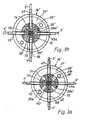
- the first variant of the second embodiment only four rod extensions 42 ', 43', 67, 68, which are mounted at equidistant circumferential distances and non-designated transverse axes pivotally mounted on the support disc 37 '.
- the transverse axes are in turn arranged along a circle shown with a broken line 69.
- the torsion spring 40 on the one hand to a connecting element 41' and on the other hand to a central hub 38 'of the mounting plate 37' attached.
- a central hub 38 "with a cylindrical, hollow, hatched passage 74 is formed, which is not occupied by a torsion spring or another part of the holding element itself, but for receiving, for example, further fasteners and preferably an electrical cable gland in the application of the support structure for clamping and holding a lampshade can serve. Therefore, instead of the central torsion spring of the first variant, a steel spring 75 in a recess 76 of the support plate 77 is arranged so that on the one hand on the support plate 77 and on the other hand - possibly via a fixed connection element 78 - on the rotatable locking plate 39 'attacks.
- the steel spring 75 in the same way with the locking plate 39 'cooperate as the torsion spring 40 in the first variant of the second embodiment, ie the in Fig. 3c under tension of the steel spring 75 standing lock plate 39 'in the released state from the in Fig. 3c shown locked position in the in Fig. 3d rotate shown position in which leg of the rod extensions 42 ', 43', 67, 68 can swing out through the radial cuts 70, 71, 72, 73 of the locking plate 39 ', whereby the elastic rods on the rod extensions 42', 43 ', 67 , 68 are relieved.
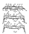
- the third embodiment of the holding member 49 according to the FIGS. 4 to 6 differs from the second embodiment essentially in that the holding member 49 comprises an annular support disc 50 in which the rod extensions 42, 43 about transverse axes 51, 52 pivotally articulated, wherein an inner disc 53 with an external thread 54 in an internal thread 55 of the annular Retaining washer is screwed.
- the inner disk 53 receives in its upper portion the locking plate 39, which may be formed as in the second embodiment.
- the rod extensions, eg 42, 43 cooperate, as in the second embodiment, with the blocking plate 39, in particular the supporting surfaces 48a, 48b, which are arranged at the bottom of the blocking plate 39.
- a torsion spring 56 is arranged in a central hub-shaped part 58 of the inner disk 53, it acts like the torsion spring 40 including the locking in the second embodiment.
- the torsion spring 56 which engages the lock plate 39 can be tensioned from above by a handle member 39a or from below by a lower actuator 60 by turning the lock plate 39 to the lock rotational position and being locked, with the inner legs not designated the rod extensions 42, 43 abut from below on the support surfaces 48a and 48b.
- the locking of the torsion spring 56 can by pressure on the support plate 37, for example, pressure points analogous to the pressure points 37 a, b in Fig. 3a - 3d be solved from above.
- the torsion spring 56 is previously stretched either by the lower actuator 60 or the actuator 39a on top of the lock plate 39, wherein the lock plate 39 in the lock rotational position according to FIG. 4 arrives.
- the locking plate 39 is in the open rotational position, so that the rod extensions 42, 43 upwards by radial cuts in the locking plate 39 and slots in an outer portion of the inner pane 53 and in the annular support plate 50 from the holding element 49 can pivot upwards, whereby the rods relax with the rod ends, eg 1a and 4a and no longer abut against the abutment pieces 46a, 46b.
- FIG. 3 illustrates how end portions 62 and 63, respectively, are preferably disposed in outer portions of bar extensions 64,65 so that end portions 62,63 can not be twisted in bar extensions 64,65.
- the end portion 62 in FIG. 7 square cross sections.
- For round cross sections such as those of the end portion 63 in FIG. 8 prevents a cross pin 66 through the end portion a rotation.
- the lower bar end 14 with square cross-sections according to FIG. 9 is non-rotatably mounted on the foot 15 to serve for stably setting up, for example, a dome tent.
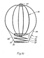
- the shape of a hollow body 79 is determined by a spacer 81 of resilient material, other than a supporting structure generally indicated at 80, which is here realized as a helical compression spring.
- the spring is formed substantially helically. It rests with an upper annular end 82 on the inside at a lower approximately spherical portion 83 of the tensioned support structure 80 and with a lower annular end 84 at a lower, optionally reinforced end of a substantially frusto-conical portion 85 of the clamped sheet material 86, which tightens overall takes the form of a balloon.
- Retaining elements of the support structure which may be formed in principle as the retaining elements described above, are designated 87, 88.
Landscapes
- Engineering & Computer Science (AREA)
- Architecture (AREA)
- Civil Engineering (AREA)
- Structural Engineering (AREA)
- General Engineering & Computer Science (AREA)
- Tents Or Canopies (AREA)
Claims (12)
- Construction porteuse destinée en particulier à du matériau plat pouvant être tendu en tant que corps creux, comprenant des tiges élastiques (1 - 6, 1' - 4') en tant que moyens de serrage pouvant être bloqués et détachés, qui sont appropriées pour tendre le matériau plat dans l'état bloqué, et qui sont en particulier au moins partiellement entourées par le matériau plat, sachant que des prolongements de tige (7 - 12, 42, 42', 43, 43', 64, 65, 67, 68) sont placés sur des extrémités des tiges (1 - 6, 1' - 4') reposant sensiblement dans un plan, lesquels sont articulés pivotants sur un axe transversal (23 - 28, 51, 52) à distance l'un de l'autre dans un agencement annulaire sur au moins un élément de retenue (13, 36, 36', 36", 49) central, sachant que les prolongements de tige (7 - 12, 42, 42', 43, 43', 64, 65, 67, 68) peuvent être bloqués collectivement sur l'au moins un élément de retenue (13, 36, 36', 36", 49) de telle manière qu'ils ne peuvent de toute façon pas pivoter sur les axes transversaux (23 - 28, 51, 52) dans un sens de pivotement dans l'état bloqué, caractérisée en ce que les prolongements de tige (42, 43) présentent respectivement une pièce d'appui coudée (46a, 46b) qui est appropriée pour appuyer une extrémité de tige (1a, 4a) pliée.
- Construction porteuse selon la revendication 1, caractérisée en ce qu'un élément de blocage plat (32, 39, 39') est disposé à l'intérieur et au centre de l'au moins un élément de retenue (13, 36, 36', 36", 49) et que les prolongements de tige (7 - 12, 42, 42', 43, 43', 67, 68) sont disposés dans l'élément de retenue (13, 36, 36', 36", 49) dans une zone extérieure radiale, font saillie radialement vers l'intérieur par rapport à l'élément de blocage (32, 39, 39'), et dans l'état bloqué, reposent sur une surface d'appui sur une face inférieure ou supérieure de l'élément de blocage (32, 39, 39').
- Construction porteuse selon la revendication 1 ou 2, caractérisée en ce que l'élément de retenue (13) est conçu en tant que disque de fixation (16) et que dans le disque de fixation (16), un disque de blocage (32) en tant qu'élément de blocage est monté rotatif avec la surface d'appui (33) sur laquelle les prolongements de tige (7-12) peuvent être appuyés.
- Construction porteuse selon la revendication 3, caractérisée en ce que le disque de fixation (16) présente des tronçons de fond inclinés (29, 30) sous des tronçons inférieurs (7a, 10a) des prolongements de tige (7-12), que la surface d'appui (33) sur la face inférieure du disque de blocage (32) est biseautée de manière conique et que le disque de blocage (32) est réglable en hauteur.
- Construction porteuse selon la revendication 3 ou 4, caractérisée en ce qu'au moins un réglage manuel (34) est relié au disque de blocage (32), lequel réglage fait saillie du disque de fixation (16) au-dessus du disque de blocage (32).
- Construction porteuse selon la revendication 4 ou 5, caractérisée en ce que le disque de fixation (16, 37, 37', 77) est un plateau essentiellement massif qui est fendu radialement pour recevoir les prolongements de tige (7 - 12, 42, 42', 43, 43', 67, 68).
- Construction porteuse selon la revendication 6, caractérisée en ce que le disque de fixation (16) est doté d'un trou fileté central (31) dans lequel le disque de blocage (32) est réglable en hauteur.
- Construction porteuse selon la revendication 6, caractérisée en ce qu'un plateau de blocage (39) est monté rotatif dans le disque de fixation coaxialement à un moyeu (38) central sur un tronçon supérieur du disque de fixation (37, 37', 77) et que le plateau de blocage (39, 39') présente des entailles radiales (70 - 73) de telle sorte que les prolongements de tige (42, 42', 43, 43', 67, 68) sont appropriés pour passer à travers les entailles (70 - 73) dans une position de rotation ouverte du plateau de blocage (39, 39') et reposer sur le plateau de blocage (39, 39') dans une position de rotation de blocage de celui-ci.
- Construction porteuse selon l'une des revendications 1 - 3, caractérisée en ce que l'élément de retenue comprend un disque de fixation annulaire (50), que les prolongements de tige (42, 43) sont articulés dans le disque annulaire de fixation (50), qu'un disque intérieur (53) est placé réglable en hauteur dans le disque de fixation annulaire (50) de telle sorte qu'il puisse être tourné vers le bas pour être sorti partiellement hors du disque de fixation annulaire (50) et que sur un tronçon supérieur du disque intérieur (53), un plateau de blocage (39) est monté rotatif, lequel présente des entailles radiales, que les prolongements de tige (42, 43) sont appropriés pour passer à travers les entailles dans une position de rotation ouverte du plateau de blocage (39, 39') et reposer sur le plateau de blocage (39, 39') dans une position de rotation de blocage de celui-ci.
- Construction porteuse selon la revendication 8 ou 9, caractérisée en ce que le plateau de blocage (39, 39') est précontraint par un ressort (40, 56, 75) par rapport au disque de fixation (37, 37', 77) respectivement au disque intérieur (53), que le plateau de blocage (39, 39') peut être bloqué en position de blocage par un appui des prolongements de tige (42, 42', 43, 43', 67, 68) via les tiges élastiques (1 - 6, 1' - 4') et que le plateau de blocage (39, 39') peut être détaché des prolongements de tige (42, 43) par le déplacement manuel axial du disque de fixation (37, 37') respectivement du disque intérieur (53) et est rotatif en position ouverte par le ressort (40, 56, 75).
- Construction porteuse selon l'une des revendications précédentes, caractérisée en ce que les prolongements de tige (42, 43, 42', 43', 67, 68) présentent respectivement deux branches (44, 45) pliées l'une contre l'autre, desquelles respectivement une première des branches (44) est reliée à une extrémité de tige (1a, 4a) et une deuxième des deux branches (45) peut être fixée, respectivement, détachée et pivotée dans l'élément de retenue (13, 36, 36', 49).
- Construction porteuse selon l'une des revendications précédentes, caractérisée en ce que respectivement une section d'extrémité (62, 63) d'une des tiges (1 - 6, 1' - 4') est placée sans pouvoir tourner dans un des prolongements de tige (64, 65).
Priority Applications (1)
| Application Number | Priority Date | Filing Date | Title |
|---|---|---|---|
| EP08022477.7A EP2090723B1 (fr) | 2008-01-26 | 2008-01-26 | Structure porteuse pour du matériau plat en particulier pouvant être tendu en tant que corps creux |
Applications Claiming Priority (2)
| Application Number | Priority Date | Filing Date | Title |
|---|---|---|---|
| EP08022477.7A EP2090723B1 (fr) | 2008-01-26 | 2008-01-26 | Structure porteuse pour du matériau plat en particulier pouvant être tendu en tant que corps creux |
| EP08001481A EP2083134A1 (fr) | 2008-01-26 | 2008-01-26 | Structure porteuse pour du matériau plat en particulier pouvant être tendu en tant que corps creux |
Related Parent Applications (3)
| Application Number | Title | Priority Date | Filing Date |
|---|---|---|---|
| EP08001481A Division-Into EP2083134A1 (fr) | 2008-01-26 | 2008-01-26 | Structure porteuse pour du matériau plat en particulier pouvant être tendu en tant que corps creux |
| EP08001481A Division EP2083134A1 (fr) | 2008-01-26 | 2008-01-26 | Structure porteuse pour du matériau plat en particulier pouvant être tendu en tant que corps creux |
| EP08001481.4 Division | 2008-01-26 |
Publications (2)
| Publication Number | Publication Date |
|---|---|
| EP2090723A1 EP2090723A1 (fr) | 2009-08-19 |
| EP2090723B1 true EP2090723B1 (fr) | 2013-05-01 |
Family
ID=39563510
Family Applications (3)
| Application Number | Title | Priority Date | Filing Date |
|---|---|---|---|
| EP08001481A Withdrawn EP2083134A1 (fr) | 2008-01-26 | 2008-01-26 | Structure porteuse pour du matériau plat en particulier pouvant être tendu en tant que corps creux |
| EP08022477.7A Not-in-force EP2090723B1 (fr) | 2008-01-26 | 2008-01-26 | Structure porteuse pour du matériau plat en particulier pouvant être tendu en tant que corps creux |
| EP09704033A Withdrawn EP2240658A1 (fr) | 2008-01-26 | 2009-01-26 | Structure support pour matériau plat pouvant être étendu, notamment pour former un corps creux |
Family Applications Before (1)
| Application Number | Title | Priority Date | Filing Date |
|---|---|---|---|
| EP08001481A Withdrawn EP2083134A1 (fr) | 2008-01-26 | 2008-01-26 | Structure porteuse pour du matériau plat en particulier pouvant être tendu en tant que corps creux |
Family Applications After (1)
| Application Number | Title | Priority Date | Filing Date |
|---|---|---|---|
| EP09704033A Withdrawn EP2240658A1 (fr) | 2008-01-26 | 2009-01-26 | Structure support pour matériau plat pouvant être étendu, notamment pour former un corps creux |
Country Status (2)
| Country | Link |
|---|---|
| EP (3) | EP2083134A1 (fr) |
| WO (1) | WO2009092615A1 (fr) |
Families Citing this family (3)
| Publication number | Priority date | Publication date | Assignee | Title |
|---|---|---|---|---|
| DE102013005986A1 (de) * | 2013-04-08 | 2014-10-09 | Wacker Neuson Produktion GmbH & Co. KG | Transportable Leuchtvorrichtung mit Biegestäben |
| SE542936C2 (en) * | 2018-11-07 | 2020-09-15 | Inter Ikea Systems B V [Nl] | Ligthing device comprising a control means for altering its appearance and light dispersion pattern |
| CN112945407B (zh) * | 2021-03-12 | 2022-07-15 | 姬广凌 | 一种儿科用防摔体温计保护装置 |
Family Cites Families (12)
| Publication number | Priority date | Publication date | Assignee | Title |
|---|---|---|---|---|
| US2953145A (en) * | 1955-07-19 | 1960-09-20 | Charles W Moss | Folding portable shelter |
| DE7009309U (de) | 1970-03-13 | 1970-09-03 | Staff & Schwarz Gmbh | Zusammenlegbarer lampenschirm. |
| BE763977A (fr) | 1970-03-13 | 1971-08-02 | Staff & Schwarz G M B H | Abat-jour pliable |
| CA1281607C (fr) * | 1987-10-05 | 1991-03-19 | Her Majesty The Queen In Right Of Canada As Represented By The Minister Of National Defence Of Her Majesty's Canadian Government | Organe de commande et manoeuvre pour groupement d'arme sur noeud central |
| US4966178A (en) * | 1989-09-14 | 1990-10-30 | The Quaker Oats Company | Tent movable between a collapsed position and a latched erect position |
| US5046882A (en) * | 1989-09-27 | 1991-09-10 | Bae Jin Corporation | Tent frame folding device |
| GB9021994D0 (en) * | 1990-10-10 | 1990-11-21 | Park Brian W | Device for tensioning structures |
| DK0563464T3 (da) | 1992-04-02 | 1998-03-30 | Baejin Corp | Teltstativforbindelsesanordning |
| DE29910204U1 (de) | 1999-06-11 | 2000-03-23 | Nölle, Jürgen, Dipl.-Ing., 47495 Rheinberg | Federschirmleuchte |
| GB0202960D0 (en) * | 2002-02-08 | 2002-03-27 | Gardner Michael | Frame clamp |
| GB0203483D0 (en) * | 2002-02-14 | 2002-04-03 | Q E F Products Ltd | Foldable frame assembly |
| DE10346948B4 (de) | 2003-10-09 | 2005-09-22 | Markus Prechtl | Tragkonstruktion für Kuppelzelte |
-
2008
- 2008-01-26 EP EP08001481A patent/EP2083134A1/fr not_active Withdrawn
- 2008-01-26 EP EP08022477.7A patent/EP2090723B1/fr not_active Not-in-force
-
2009
- 2009-01-26 WO PCT/EP2009/000483 patent/WO2009092615A1/fr not_active Ceased
- 2009-01-26 EP EP09704033A patent/EP2240658A1/fr not_active Withdrawn
Also Published As
| Publication number | Publication date |
|---|---|
| WO2009092615A1 (fr) | 2009-07-30 |
| EP2083134A1 (fr) | 2009-07-29 |
| EP2090723A1 (fr) | 2009-08-19 |
| EP2240658A1 (fr) | 2010-10-20 |
Similar Documents
| Publication | Publication Date | Title |
|---|---|---|
| DE4333913A1 (de) | Einstellvorrichtung an längen- und neigungsverstellbaren Haltern, insbesondere für Percussions-Musikinstrumente | |
| WO1992018038A1 (fr) | Socle pour arbre de noël | |
| DE3531087A1 (de) | Bodenbefestigungsvorrichtung | |
| EP2348926B1 (fr) | Support pour arbre | |
| EP2090723B1 (fr) | Structure porteuse pour du matériau plat en particulier pouvant être tendu en tant que corps creux | |
| EP4064939A1 (fr) | Structure de raccordement de tuyau et kit de meuble | |
| DE102007025227B4 (de) | Ständer zum Aufspannen von mast- oder stammförmigen Teilen, insbesondere zum Aufspannen von Christbäumen | |
| DE102016114481B4 (de) | Klappbarer Schirmständer | |
| EP1085257B1 (fr) | Projecteur d'éclairage avec verrouillage de l'articulation | |
| EP2159353A2 (fr) | Dispositif de mise en tension | |
| DE29905420U1 (de) | Halterung für ein Gerät | |
| DE19826380B4 (de) | Osteosynthetisches Befestigungssystem | |
| DE102004043192B4 (de) | Tisch | |
| WO1999009901A1 (fr) | Dispositif pour relier une tige a un autre implant | |
| WO2002067736A1 (fr) | Montant pour fixer et maintenir en position verticale des elements sous forme de barres | |
| DE102023118570B4 (de) | Kopplungsvorrichtung | |
| DE102017116844B3 (de) | Stabilisatorstangeneinheit für Sonnenschutz | |
| DE602004000767T2 (de) | Schliess- und Spannvorrichtung für Sportschuh | |
| DE20001066U1 (de) | Befestigungsvorrichtung für einen Toilettensitz | |
| CH697318B1 (de) | Einbauleuchte mit einer Fixiervorrichtung zu ihrer Fixierung in einer Einbauöffnung. | |
| DE10138065B4 (de) | Federbelasteter Umleggriff | |
| DE102015122892B4 (de) | Weihnachtsbaumständer | |
| DE29619925U1 (de) | Verbindungskonstruktion für Stehlampen | |
| EP0126979A2 (fr) | Support pour un arbre de Noel, un parasol ou pareil | |
| DE202016101572U1 (de) | Verbindungsmodul, Verbindungselement und lösbare Verbindung für Möbelstücke sowie Möbelstück |
Legal Events
| Date | Code | Title | Description |
|---|---|---|---|
| PUAI | Public reference made under article 153(3) epc to a published international application that has entered the european phase |
Free format text: ORIGINAL CODE: 0009012 |
|
| 17P | Request for examination filed |
Effective date: 20090415 |
|
| AC | Divisional application: reference to earlier application |
Ref document number: 2083134 Country of ref document: EP Kind code of ref document: P |
|
| AK | Designated contracting states |
Kind code of ref document: A1 Designated state(s): AT BE BG CH CY CZ DE DK EE ES FI FR GB GR HR HU IE IS IT LI LT LU LV MC MT NL NO PL PT RO SE SI SK TR |
|
| AX | Request for extension of the european patent |
Extension state: AL BA MK RS |
|
| AKX | Designation fees paid |
Designated state(s): AT BE BG CH CY CZ DE DK EE ES FI FR GB GR HR HU IE IS IT LI LT LU LV MC MT NL NO PL PT RO SE SI SK TR |
|
| GRAP | Despatch of communication of intention to grant a patent |
Free format text: ORIGINAL CODE: EPIDOSNIGR1 |
|
| GRAS | Grant fee paid |
Free format text: ORIGINAL CODE: EPIDOSNIGR3 |
|
| GRAA | (expected) grant |
Free format text: ORIGINAL CODE: 0009210 |
|
| AC | Divisional application: reference to earlier application |
Ref document number: 2083134 Country of ref document: EP Kind code of ref document: P |
|
| AK | Designated contracting states |
Kind code of ref document: B1 Designated state(s): AT BE BG CH CY CZ DE DK EE ES FI FR GB GR HR HU IE IS IT LI LT LU LV MC MT NL NO PL PT RO SE SI SK TR |
|
| REG | Reference to a national code |
Ref country code: GB Ref legal event code: FG4D Free format text: NOT ENGLISH |
|
| REG | Reference to a national code |
Ref country code: AT Ref legal event code: REF Ref document number: 610053 Country of ref document: AT Kind code of ref document: T Effective date: 20130515 Ref country code: CH Ref legal event code: EP |
|
| REG | Reference to a national code |
Ref country code: IE Ref legal event code: FG4D Free format text: LANGUAGE OF EP DOCUMENT: GERMAN |
|
| REG | Reference to a national code |
Ref country code: DE Ref legal event code: R096 Ref document number: 502008009826 Country of ref document: DE Effective date: 20130627 |
|
| REG | Reference to a national code |
Ref country code: NL Ref legal event code: VDEP Effective date: 20130501 |
|
| REG | Reference to a national code |
Ref country code: LT Ref legal event code: MG4D |
|
| PG25 | Lapsed in a contracting state [announced via postgrant information from national office to epo] |
Ref country code: GR Free format text: LAPSE BECAUSE OF FAILURE TO SUBMIT A TRANSLATION OF THE DESCRIPTION OR TO PAY THE FEE WITHIN THE PRESCRIBED TIME-LIMIT Effective date: 20130802 Ref country code: SI Free format text: LAPSE BECAUSE OF FAILURE TO SUBMIT A TRANSLATION OF THE DESCRIPTION OR TO PAY THE FEE WITHIN THE PRESCRIBED TIME-LIMIT Effective date: 20130501 Ref country code: IS Free format text: LAPSE BECAUSE OF FAILURE TO SUBMIT A TRANSLATION OF THE DESCRIPTION OR TO PAY THE FEE WITHIN THE PRESCRIBED TIME-LIMIT Effective date: 20130901 Ref country code: SE Free format text: LAPSE BECAUSE OF FAILURE TO SUBMIT A TRANSLATION OF THE DESCRIPTION OR TO PAY THE FEE WITHIN THE PRESCRIBED TIME-LIMIT Effective date: 20130501 Ref country code: FI Free format text: LAPSE BECAUSE OF FAILURE TO SUBMIT A TRANSLATION OF THE DESCRIPTION OR TO PAY THE FEE WITHIN THE PRESCRIBED TIME-LIMIT Effective date: 20130501 Ref country code: ES Free format text: LAPSE BECAUSE OF FAILURE TO SUBMIT A TRANSLATION OF THE DESCRIPTION OR TO PAY THE FEE WITHIN THE PRESCRIBED TIME-LIMIT Effective date: 20130812 Ref country code: PT Free format text: LAPSE BECAUSE OF FAILURE TO SUBMIT A TRANSLATION OF THE DESCRIPTION OR TO PAY THE FEE WITHIN THE PRESCRIBED TIME-LIMIT Effective date: 20130902 Ref country code: LT Free format text: LAPSE BECAUSE OF FAILURE TO SUBMIT A TRANSLATION OF THE DESCRIPTION OR TO PAY THE FEE WITHIN THE PRESCRIBED TIME-LIMIT Effective date: 20130501 Ref country code: NO Free format text: LAPSE BECAUSE OF FAILURE TO SUBMIT A TRANSLATION OF THE DESCRIPTION OR TO PAY THE FEE WITHIN THE PRESCRIBED TIME-LIMIT Effective date: 20130801 |
|
| PG25 | Lapsed in a contracting state [announced via postgrant information from national office to epo] |
Ref country code: BG Free format text: LAPSE BECAUSE OF FAILURE TO SUBMIT A TRANSLATION OF THE DESCRIPTION OR TO PAY THE FEE WITHIN THE PRESCRIBED TIME-LIMIT Effective date: 20130801 Ref country code: CY Free format text: LAPSE BECAUSE OF FAILURE TO SUBMIT A TRANSLATION OF THE DESCRIPTION OR TO PAY THE FEE WITHIN THE PRESCRIBED TIME-LIMIT Effective date: 20130501 Ref country code: PL Free format text: LAPSE BECAUSE OF FAILURE TO SUBMIT A TRANSLATION OF THE DESCRIPTION OR TO PAY THE FEE WITHIN THE PRESCRIBED TIME-LIMIT Effective date: 20130501 Ref country code: HR Free format text: LAPSE BECAUSE OF FAILURE TO SUBMIT A TRANSLATION OF THE DESCRIPTION OR TO PAY THE FEE WITHIN THE PRESCRIBED TIME-LIMIT Effective date: 20130501 |
|
| PG25 | Lapsed in a contracting state [announced via postgrant information from national office to epo] |
Ref country code: LV Free format text: LAPSE BECAUSE OF FAILURE TO SUBMIT A TRANSLATION OF THE DESCRIPTION OR TO PAY THE FEE WITHIN THE PRESCRIBED TIME-LIMIT Effective date: 20130501 |
|
| PG25 | Lapsed in a contracting state [announced via postgrant information from national office to epo] |
Ref country code: EE Free format text: LAPSE BECAUSE OF FAILURE TO SUBMIT A TRANSLATION OF THE DESCRIPTION OR TO PAY THE FEE WITHIN THE PRESCRIBED TIME-LIMIT Effective date: 20130501 Ref country code: SK Free format text: LAPSE BECAUSE OF FAILURE TO SUBMIT A TRANSLATION OF THE DESCRIPTION OR TO PAY THE FEE WITHIN THE PRESCRIBED TIME-LIMIT Effective date: 20130501 Ref country code: DK Free format text: LAPSE BECAUSE OF FAILURE TO SUBMIT A TRANSLATION OF THE DESCRIPTION OR TO PAY THE FEE WITHIN THE PRESCRIBED TIME-LIMIT Effective date: 20130501 Ref country code: CZ Free format text: LAPSE BECAUSE OF FAILURE TO SUBMIT A TRANSLATION OF THE DESCRIPTION OR TO PAY THE FEE WITHIN THE PRESCRIBED TIME-LIMIT Effective date: 20130501 |
|
| PG25 | Lapsed in a contracting state [announced via postgrant information from national office to epo] |
Ref country code: NL Free format text: LAPSE BECAUSE OF FAILURE TO SUBMIT A TRANSLATION OF THE DESCRIPTION OR TO PAY THE FEE WITHIN THE PRESCRIBED TIME-LIMIT Effective date: 20130501 Ref country code: RO Free format text: LAPSE BECAUSE OF FAILURE TO SUBMIT A TRANSLATION OF THE DESCRIPTION OR TO PAY THE FEE WITHIN THE PRESCRIBED TIME-LIMIT Effective date: 20130501 Ref country code: IT Free format text: LAPSE BECAUSE OF FAILURE TO SUBMIT A TRANSLATION OF THE DESCRIPTION OR TO PAY THE FEE WITHIN THE PRESCRIBED TIME-LIMIT Effective date: 20130501 |
|
| PLBE | No opposition filed within time limit |
Free format text: ORIGINAL CODE: 0009261 |
|
| STAA | Information on the status of an ep patent application or granted ep patent |
Free format text: STATUS: NO OPPOSITION FILED WITHIN TIME LIMIT |
|
| 26N | No opposition filed |
Effective date: 20140204 |
|
| REG | Reference to a national code |
Ref country code: DE Ref legal event code: R097 Ref document number: 502008009826 Country of ref document: DE Effective date: 20140204 |
|
| BERE | Be: lapsed |
Owner name: ATIKER, YUCEL Effective date: 20140131 |
|
| REG | Reference to a national code |
Ref country code: DE Ref legal event code: R119 Ref document number: 502008009826 Country of ref document: DE |
|
| PG25 | Lapsed in a contracting state [announced via postgrant information from national office to epo] |
Ref country code: LU Free format text: LAPSE BECAUSE OF FAILURE TO SUBMIT A TRANSLATION OF THE DESCRIPTION OR TO PAY THE FEE WITHIN THE PRESCRIBED TIME-LIMIT Effective date: 20140126 Ref country code: MC Free format text: LAPSE BECAUSE OF FAILURE TO SUBMIT A TRANSLATION OF THE DESCRIPTION OR TO PAY THE FEE WITHIN THE PRESCRIBED TIME-LIMIT Effective date: 20130501 |
|
| REG | Reference to a national code |
Ref country code: CH Ref legal event code: PL |
|
| GBPC | Gb: european patent ceased through non-payment of renewal fee |
Effective date: 20140126 |
|
| REG | Reference to a national code |
Ref country code: DE Ref legal event code: R119 Ref document number: 502008009826 Country of ref document: DE Effective date: 20140801 |
|
| PG25 | Lapsed in a contracting state [announced via postgrant information from national office to epo] |
Ref country code: LI Free format text: LAPSE BECAUSE OF NON-PAYMENT OF DUE FEES Effective date: 20140131 Ref country code: DE Free format text: LAPSE BECAUSE OF NON-PAYMENT OF DUE FEES Effective date: 20140801 Ref country code: CH Free format text: LAPSE BECAUSE OF NON-PAYMENT OF DUE FEES Effective date: 20140131 |
|
| REG | Reference to a national code |
Ref country code: FR Ref legal event code: ST Effective date: 20140930 |
|
| REG | Reference to a national code |
Ref country code: IE Ref legal event code: MM4A |
|
| PG25 | Lapsed in a contracting state [announced via postgrant information from national office to epo] |
Ref country code: GB Free format text: LAPSE BECAUSE OF NON-PAYMENT OF DUE FEES Effective date: 20140126 Ref country code: FR Free format text: LAPSE BECAUSE OF NON-PAYMENT OF DUE FEES Effective date: 20140131 |
|
| PG25 | Lapsed in a contracting state [announced via postgrant information from national office to epo] |
Ref country code: BE Free format text: LAPSE BECAUSE OF NON-PAYMENT OF DUE FEES Effective date: 20140131 Ref country code: IE Free format text: LAPSE BECAUSE OF NON-PAYMENT OF DUE FEES Effective date: 20140126 |
|
| REG | Reference to a national code |
Ref country code: AT Ref legal event code: MM01 Ref document number: 610053 Country of ref document: AT Kind code of ref document: T Effective date: 20140126 |
|
| PG25 | Lapsed in a contracting state [announced via postgrant information from national office to epo] |
Ref country code: AT Free format text: LAPSE BECAUSE OF NON-PAYMENT OF DUE FEES Effective date: 20140126 |
|
| PG25 | Lapsed in a contracting state [announced via postgrant information from national office to epo] |
Ref country code: MT Free format text: LAPSE BECAUSE OF FAILURE TO SUBMIT A TRANSLATION OF THE DESCRIPTION OR TO PAY THE FEE WITHIN THE PRESCRIBED TIME-LIMIT Effective date: 20130501 |
|
| PG25 | Lapsed in a contracting state [announced via postgrant information from national office to epo] |
Ref country code: TR Free format text: LAPSE BECAUSE OF FAILURE TO SUBMIT A TRANSLATION OF THE DESCRIPTION OR TO PAY THE FEE WITHIN THE PRESCRIBED TIME-LIMIT Effective date: 20130501 Ref country code: HU Free format text: LAPSE BECAUSE OF FAILURE TO SUBMIT A TRANSLATION OF THE DESCRIPTION OR TO PAY THE FEE WITHIN THE PRESCRIBED TIME-LIMIT; INVALID AB INITIO Effective date: 20080126 |