EP2159353A2 - Dispositif de mise en tension - Google Patents
Dispositif de mise en tension Download PDFInfo
- Publication number
- EP2159353A2 EP2159353A2 EP20090011135 EP09011135A EP2159353A2 EP 2159353 A2 EP2159353 A2 EP 2159353A2 EP 20090011135 EP20090011135 EP 20090011135 EP 09011135 A EP09011135 A EP 09011135A EP 2159353 A2 EP2159353 A2 EP 2159353A2
- Authority
- EP
- European Patent Office
- Prior art keywords
- clamping device
- adjustable column
- axially adjustable
- carrier body
- rod
- Prior art date
- Legal status (The legal status is an assumption and is not a legal conclusion. Google has not performed a legal analysis and makes no representation as to the accuracy of the status listed.)
- Withdrawn
Links
- 238000006073 displacement reaction Methods 0.000 claims description 17
- 239000000463 material Substances 0.000 claims description 7
- 230000000295 complement effect Effects 0.000 claims description 2
- 238000005452 bending Methods 0.000 description 6
- 230000006835 compression Effects 0.000 description 6
- 238000007906 compression Methods 0.000 description 6
- 238000010276 construction Methods 0.000 description 4
- 239000004753 textile Substances 0.000 description 2
- 244000089486 Phragmites australis subsp australis Species 0.000 description 1
- 230000000903 blocking effect Effects 0.000 description 1
- 238000005516 engineering process Methods 0.000 description 1
- 230000005764 inhibitory process Effects 0.000 description 1
- 238000000034 method Methods 0.000 description 1
- 238000004806 packaging method and process Methods 0.000 description 1
- 230000001737 promoting effect Effects 0.000 description 1
- 230000002040 relaxant effect Effects 0.000 description 1
- 230000000284 resting effect Effects 0.000 description 1
- 230000000717 retained effect Effects 0.000 description 1
Images






Classifications
-
- E—FIXED CONSTRUCTIONS
- E04—BUILDING
- E04H—BUILDINGS OR LIKE STRUCTURES FOR PARTICULAR PURPOSES; SWIMMING OR SPLASH BATHS OR POOLS; MASTS; FENCING; TENTS OR CANOPIES, IN GENERAL
- E04H15/00—Tents or canopies, in general
- E04H15/32—Parts, components, construction details, accessories, interior equipment, specially adapted for tents, e.g. guy-line equipment, skirts, thresholds
- E04H15/322—Stretching devices
Definitions
- the invention relates to a clamping device according to the preamble of claim 1.
- the invention aims at a tensioning device which is the only tensioning device, e.g. can be used in a bar structure of a quick-erecting tent, or which can be used together with a second tensioning device at two ends of an object to be suspended, such as spherical or ball-like lamps, string constructions, or light bands, or for promotional textiles.
- the clamping device comprises a central carrier body, which is formed in two parts with an upper housing part and a lower housing part. In the carrier body, ends of the tent rods project radially inwards. On a mounted in the upper housing part cylinder, a column-shaped slider is mounted axially displaceable.
- the counterpart consists of an outer column and an inner column, which are concentrically set together, leaving a hollow cylindrical receiving space into which the cylinder extends.
- On the outer pillar outside racks are formed, engage in the formed as a gear sectors end pieces of the tent poles.
- the gear sectors are pivotally mounted transversely to an axial fictitious main axis of the clamping device.
- the toothings of the racks and the gear sectors may also be helical, but the racks are not rotatable about the major axis.
- a compression spring is used, which is supported on the slider and the cylinder.
- a tension spring is inserted into the inner column to apply a tension to the slider.
- a locking pin is arranged below, which engages in a corresponding recess in a disposed in the lower housing part button in a lower end position of the slider.
- the tent poles are pivoted up to move the slider down by the racks, which are driven by the gear sectors, which is supported by the compression spring.
- the tension spring is tensioned.
- the locking pin engages the knob in the housing to lock the clamping device in this end position.
- the lock is released by pressing the button, and the slider slides up under the tension of the tension spring. In this case, the linear movement of the slider is converted into a pivoting of the tent poles by the arrangement of the racks and gear sectors.
- US-A-5 046 882 includes a folding device of a tent frame with a locking cap, which can include with a band stepped elevations on fittings of tent poles, so that the pivotally mounted about transverse axes connecting pieces are held in a locking position of the locking cap in an unfolded state.
- the locking cap may be urged to an unlocked position by a compression spring when a lever pressing with an end cam on the top of the locking cap is pivoted to a position in which the cam permits lifting of the locking cap from the links of the tent poles.
- the invention has for its object to provide an uncomplicated reliable clamping device, which is universally applicable, with the clamping of several, brought together in the fixture rods is effectively facilitated, with the stiff rods in a desired shape can be bent and with which the rods can be permanently clamped not only in a locked end position.
- the invention is based on a clamping device for rods, in particular elastic rods, which are suitable to open up sheet material, in particular to a hollow body, wherein ends of the rods in a carrier body of the clamping device spaced from each other about a transverse axis are pivotally mounted, wherein The ends of the rods gear sectors are arranged and wherein the tensioning device comprises a central, axially adjustable in the support body pillar having at least a first toothing outside, engage in the gear sectors, so that they are pivoted in an adjustment of the column.
- the invention consists in that the axially adjustable column is rotatably mounted in a cylindrical interior of the carrier body and that the cylindrical interior of the carrier body has at least one internal thread into which at least one external thread on the axially adjustable column can engage self-locking.
- a large adjustment can be realized.
- a clamping pressure can be exerted on several rods simultaneously and uniformly, so that the rods outwardly from a center of a wrapped by the bars shape, such as the shape of a tent or a spherical shape, under the action of large forces or Moments can be safely clamped and can be fixed in this state, but also in intermediate states.
- the internal thread in the carrier body or the external thread on the axially adjustable column at least as long as a predetermined axial displacement of the axially adjustable column, and the internal thread in the carrier body and the external thread on the adjustable column are along the predetermined axial displacement self-locking in engagement.
- the bars are automatically held in each intermediate position between their completely relaxed position and fully tensioned position.
- the internal thread in the carrier body or the external thread on the axially adjustable column consists of at least one threaded portion which is shorter than a predetermined axial adjustment.
- the strippable rods can be biased with the threads in a defined starting position, from which they can be pushed by an axial movement of the adjustable column further into the cocked position, or it is at a different arrangement of the internal thread or the external thread, the rods initially only by axial displacement of the column tensioned and only then adjustable in the end position by grape-line rotation of the internal thread in the external thread.
- both an initial position of the rods on the axially adjustable column and an end position of the rods via this column by two threaded sections infinitely adjustable with great accuracy and force, while in a central portion of the axial displacement of the axially adjustable column this moved quickly and easily manually can be made by the internal thread in the support body or the external thread on the axially adjustable column of two threaded portions, one of which at an end of a predetermined axial displacement is arranged and the other is arranged at one end of the predetermined axial displacement, and wherein the axially adjustable column between these threaded portions is axially freely displaceable.
- a rotary knob is expediently attached to one end of the axially adjustable column according to claim 5, which is preferably also suitable for pressure or tension operation.
- the clamping device is particularly suitable for clamping from the top outside, for example in a tent structure.
- the knob at the lower end of the axially adjustable column with otherwise unchanged arrangement of the axially adjustable column in the cylindrical interior of the carrier body and unchanged configuration of the transverse axes. around which the rods are pivotally mounted at their ends.
- the tensioning device can be conveniently operated from within an object or body to be tensioned.
- the clamping device has the features that the ends of the rods are each plugged into a rigid rod extension that at an inner end of the rod extension of the gear sector is arranged and that the rod extension has at its outer end a curved, laterally open rod system.
- the curvature of the rods can be set reliably defined in the clamping and occur at the ends of the rods no excessive stresses that could lead to buckling of the rod ends.
- a substantially hollow cylindrical locking bush is used at the bottom in the support body, which is connected in a lower portion of the axially adjustable column with this threaded adjustable height, below from the outer periphery of Protruding sleeve protrusions and at a lower end of the support body, a locking ring with inner radial recesses is arranged, which are adapted to pass the projections of the locking sleeve.
- the carrier body inside only need to have a portion of the internal thread, in which an external thread of an axially adjustable column can engage to set an initial tension or - form of the elastic rods. Otherwise, the column is directly axially adjustable.
- the clamping device according to claim 10 each have a central continuous channel in the axially adjustable column and in which optionally arranged at its end knob in which a rigid tube is mounted so that at a rotational adjustment the axially adjustable column does not rotate the pipe.
- the tube according to claim 11 may be an insulating tube and receive a connecting cable to a light source in the spanned by the clamping device rod structure.
- the clamping device can be further developed according to claim 12 to a motor movement by a drive unit is on the one hand with the carrier body and on the other hand with the rotatable and axially adjustable column in force-transmitting connection.
- a hanger is preferably arranged on the carrier body at the bottom, with which a tarpaulin can be suspended, so that it does not slip off the rods or tent poles to be set up during construction of the tent.
- each of the tensionable with the tensioning device rods of at least two bar sections, of which two adjacent bar sections can be interconnected.
- two rod sections are plugged into each other and connected inside by a rubber cord, so that the rod sections are each assigned to a mat together and can not be lost.
- the interconnectable bar sections may be connected according to claim 16 by a hinge to which they are pivotable to each other.
- the bars according to claim 17 preferably have the features that the joint of the bar sections comprises a transverse axis about which profiled ends of the bar sections can be pivoted, that the bar sections are profiled so that they are in a swung out state Rod sections to complement a substantially complete bar profile and that a spring-loaded sleeve can be pushed over the joint of the pivoted rod sections.
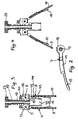
- FIG. 1 A first embodiment of the tensioning device is in FIG. 1 shown in a longitudinal section:
- a carrier body 1 with a substantially cylindrical interior 2, which is open at the top and bottom.
- lateral bulges 3, 4 of the carrier body are spaced from each other, practically tangential to an imaginary circumference circle, transverse axes attached, of which transverse axes 5, 6 in FIG. 1 are visible.
- each of the transverse axes eg 5, see also FIG. 2 , is a rigid rod extension 7, or in FIG. 1 Also 8, each pivotally mounted in a vertical plane.
- the vertical planes, not shown, run together in a star shape to a central axis of the tensioning device, which in FIG. 1 not shown.
- the rod extensions 7, 8 are rigid and provide bending elements for inserted into them elastic rods 9, 10, which are to be stretched to a rod structure, in particular a hollow body.
- the rod extension 7 comprises a tubular portion 11 in which at an inner, the central axis Z end facing a gear sector 12 is firmly inserted, and a curved, laterally open bar system 13, which serves as a support and support for an inserted elastic rod, eg a flexible tent pole. Due to the shape of the open bar system as a laterally open pipe section occur in the resting and bending of a rod or tent pole no material wear and no punctual load during bending. To the second in FIG. 1 recognizable rod extension 8 is the tubular portion 14 and the open rod system designated 15.
- the cylindrical inner space 2 of the carrier body 1 takes on an axially displaceable column 17 concentric with the central axis Z, which at its Outside has a toothing 18.
- the gear sectors 12, 16 of the rod extensions 7 and 8 in such a way that a linear movement of the axially displaceable column 17 in vertical pivotal movements of the gear sectors 12, 16 and thus the rod extensions 7 and 8 is implemented, and vice versa could Pivoting movement of the gear sectors 12, 16 are converted into a linear movement of the axially displaceable column, when the linear movement is not inhibited.
- Such an inhibition occurs in that an external thread 19 engages a lower portion of the axially displaceable column 17 in an internal thread 20, which is formed in a lower portion of the cylindrical interior 2 of the carrier body 1.
- the external thread 19 and 23 can be axially displaced in the free portion, without rotation of a knob 23 and 24, which at one end, ie in FIGS. 1 and 7 the upper end of the axially displaceable column 17 and 25 is mounted.
- FIG. 1 is the predetermined axial displacement as long or high, as the internal thread 20 extends in the cylindrical interior 2 of the support body 1.
- the predetermined axial displacement is greater than the length or height of the internal thread 21, namely to the free portion 22. In the latter case, so is the internal thread 21, which can be regarded as a threaded portion, shorter than the predetermined axial displacement of the axially displaceable column 25th
- the second embodiment of the clamping device according to FIG. 7 is particularly suitable for setting up a quick-erecting tent.
- a carrier body 26 of the clamping device according to FIG. 7 Therefore, at the bottom of a non-designated bottom on a hanger 27 on which a tarpaulin 28 can be suspended at its uppermost point, so that the tarpaulin 28 can not slide down on elastic rods of the rod structure of the tent during a tensioning operation to be described.
- the embodiment of the tensioning device according to FIG. 7 in turn lateral bulges 29, 30 of the support body 26 on which the gear sectors 33, 34 at the inner ends of rod extensions 35, 36 about transverse axes 31, 32 are vertically pivotable.
- the gear sectors 33, 34 engage - similar to the first embodiment after FIG. 1 - In a toothing 37 on the outer circumference of the axially displaceable column 25 a.
- a continuous bore or a channel is provided, which is denoted by 38 and 39, respectively.
- the channel may serve to pass a cable, in particular when the body covered by the tensioning device shown is a lamp.
- the embodiment of the clamping device according to the Figures 3 - 6 differs in the first embodiment according to FIG. 1 in that according to the Figures 3 - 6 an internal thread in a cylindrical interior 40 in the carrier body 41 from an upper threaded portion 42, a lower threaded portion 43 and a thread-free portion 44 disposed therebetween.
- the same parts of the two embodiments are provided with identical reference numerals.
- the axially displaceable columns 17 are formed with the teeth 18 and the external thread 19 at the lower portion of the axially displaceable column the same. This is also true for the about the transverse axes 5, 6 vertically pivotable rod extensions 7, 8, at the inner ends of the gear sectors 12, 16 are arranged, which engage in the toothing 18.
- the knob 23 is pressed down and simultaneously rotated so that the external thread 19 reaches the bottom of the axially displaceable column 17 into engagement with the upper threaded portion 42 and by further rotation of the knob 23, the rod extensions with the rods 9, 10 are pivoted further outwards, the elastic rods being characterized by their weight and possibly attached Tarpaulin to the open bar facilities 13, 15 arched outwardly or bent inward, whereby the further bending direction of the rods 9, 10 is determined.
- the axially displaceable column 17 can be released from the upper threaded portion 42 and further pushed down, wherein the elastic rods 9, 10 with the predetermined bending direction can be further arched outwards and stretched until the external thread 19 at the bottom of the axially displaceable column 17 comes into engagement with the lower threaded portion 43 of the carrier body 41.
- the tensioning device in the in FIG. 6 illustrated configuration the elastic rods 9, 10 completely in the end position according to FIG. 6 tighten. As a result, the tension of the clamped tarpaulin can be finally adjusted continuously.
- FIGS. 8-11 The embodiments of the clamping device according to the FIGS. 8-11 is different from the one after the Figures 3 - 6 in that the embodiment according to the FIGS. 8-11 from the interior of the réellespannenden structure, in particular a tent, by means of a knob 45 can be actuated, which is arranged at the bottom of an axially displaceable column 46.
- a cylindrical inner space 47 in the carrier body is analogously inversely configured as the cylindrical inner space 40 of the axially displaceable column 17:
- a first threaded section 48 as an internal thread is arranged relatively deep, but above the gear sectors 12, 16.
- the axially displaceable column 46 in turn is a linear toothing 48, which is in engagement with the gear sectors 12 and 16.
- the voltage of the further swung-elastic rods 9, 10 and the spanned tarpaulin can be adjusted to its final value without further Operation of the knob 45 is maintained because the threaded portions, in particular 50, and the external thread 51 are self-locking.
- the embodiment of the clamping device according to FIG. 12 differs from the one after FIG. 1 in that the channel 56 carried by the rotary knob 54 and the axially adjustable column 55 in the carrier body 56 receives a rigid tube 57, whereas the rotary knob 54 and the axially adjustable column 55 are easily rotatable.
- the tube 57 is mounted with a ball bearing 58 in the knob 54 and with another ball bearing 59 in the axially adjustable column 55.
- an electrical cable is performed, to which a light bulb, not shown in the drawing can be connected.
- the embodiment according to FIG. 12 is therefore particularly suitable for the realization of a lamp or lamp.
- the power supply to the light source is effected by the electrical cable 60 and accident-proof, since the electrical cable 60 does not scrub on the tube 57 when the clamping device, in particular the knob 54 and the axially adjustable column 55 are rotated.
- a rotation of the entire clamping device with the exception of the tube 57 and of the electrical cable 60 may be desired, for example, when the tensioning device is used to tension a transparent indoor illuminated advertising object.
- the clamping device can be rotated with the clamped object by a drive unit 61 which engages on the one hand on the pipe and on the other hand on the rotatable and axially adjustable column non-positively.
- the drive unit 61 may in particular be connected in terms of gear technology with the rotary knob 54 via a drive gear 62 or frictionally engaged and, on the other hand, be in firm connection with the carrier body. If the tube 60 is held stationary, thus the clamping device rotates together with the object spanned by her. Since the tensioning device and the object are not retained in this case or are fixedly mounted, the drive unit 61 does not adjust the tensioning device.
- the tensioning device in the embodiment according to the FIGS. 13-16a differs from the first embodiment according to the Figures 3-6 in that a carrier body 63 has a cylindrical inner space 64 with only one threaded section 65 which extends over only part of the axial displacement path of an axially displaceable column 66 in order, as in connection with FIGS Figures 3 - 6 explains to create an initial stress and bulge in the elastic rods 9, 10.
- the axially displaceable column 66 in its lower portion, in which the external thread 67 of the axial displaceable column 66 is formed, a recess 68 with an internal thread into which a substantially hollow cylindrical locking sleeve 69 is inserted with a matching external thread and for presetting the desired in the tensioned state of the rod structure height adjustable thread-locking is connected.
- the locking sleeve has a lower collar, from the four pins or projections 70 - 73 protrude. The pins are arranged at equal circumferential intervals.
- the cylindrical interior 64 of the carrier body 63 is provided below with a locking ring 74 having four radial recesses 75-78 which are slightly larger than the pins 70-73 in the locking sleeve and how these pins are configured so that the pins 70 -. 73 can pass through the recesses 75-78 in the locking ring 74 when the locking sleeve is rotated in a suitable rotational position.
- the locking sleeve 69 is effective for clamping in the end position of the elastic rods 9, 10, this is pressed together with the axially adjustable column 66 which is released from the threaded portion 65 in the cylindrical interior 64 of the support body 63, down FIG. 14 , After the axially adjustable column 66 together with the screwed into it locking sleeve 69 in a position according to FIG. 15 is rotated, with further pressure on the axially displaceable column 66, the pins 70 - 73 pass through the recesses 75 - 78 in the locking disc on the underside of the locking ring 74.
- the tensioned axially displaceable column 66 may be released causing the pins 70-73 at the bottom of the locking ring 74 support and keep the rods 9, 10 stretched in their desired shape.
- these can relax to the tensioned by the tensioning rods 9, 10 again through the recesses 75 - 78 in the cylindrical interior 64 of the support body 63 occur and raised together with the axially adjustable column ,
- FIG. 17 there is shown a quick-erecting tent 79, a detail of which is shown in the upper portion of the quick-erecting tent 79 in FIG. 18 is shown.
- the quick-erecting tent 79 comprises a tensioning device acting on its rod structure, eg with elastic bars 9, 10, which according to FIG Figures 3 - 6 described clamping device with an axially displaceable column 17, a knob 23 and a support body 41 is constructed in the gear sectors, for example, 12 and 16, are mounted.
- the gear sectors 12, 16 are in turn in force-transmitting connection with the toothing 18 of the axially displaceable column 17, with the knob 23 and in FIG. 18 not designated threads or threaded portions can be adjusted axially, whereby the rod structure is bulged and can be kept curious in a bulged state.
- Mounted on the carrier body 41 is a hanger 27a which holds an upper portion of the tarpaulin 28a, as described above in connection with FIG FIG. 7 described.
- Each of the four tent poles of the fast construction tent 79 can be folded after relaxing all tent poles only by turning the knob 23 of the common clamping device and after tensioning the tent pole structure.
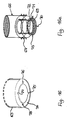
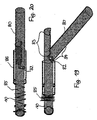
- the rod sections, for example, 10, 80, as larger in the FIGS. 19 and 20 represented, pivotally connected to each other, in each case about a joint which a transverse axis, for example, 82, in the FIGS. 19 and 20 includes.
- the elastic rods or bar sections 10, 80 pivotally connected to one another by the transverse axis 82 are profiled in their connecting region in such a way that they are in a pivoted state, see FIG. 20 , to complete a complete bar profile.
- a rod section, for example, 10, at its profile area adjacent to the transverse axis 83, as in FIG. 19 represented as a half hollow cylindrical profile which is open on one longitudinal side formed.
- a correspondingly long profile region 84 of the rod portion 80 can be pivoted.
- the profile portion 84 For unobstructed pivoting of the profile portion 84 at its transverse axis 82 facing the end, as in Fig. 19 shown, shaped.
- a compression spring 85 is disposed on the rod 10 so as to urge a sleeve 86 over the crimped abutted profile portions 84, 85 unless it is manually retracted against the force of the compression spring 85 to reciprocally pivot the rod portions 10 and 80 to allow.
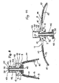
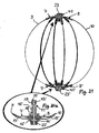
- FIG. 21 and in FIG. 21 a is shown as elastic rods, in particular the rods designated 9 and 10 in the two figures, by two clamping devices of the in the Figures 3 - 6 shown embodiment and described above can be stretched to a spherical shape as a final shape.
- FIG. 21 are the tensioning device according to FIG. 6 arranged on the spherical shape above and a second tensioning device in reverse position with the Knob 23 'outwards downwards, as in FIG. 21 a shown.
- the second, lower tensioning device carries with an 'provided reference numerals, those of the upper tensioning device or after the Figures 3 - 6 correspond.
- the spherical shape is particularly suitable as a lamp, to which in particular the bars, e.g. 9, 10, are covered in total with surface material.
- the rods, e.g. 9, 10, then push the sheet material outwards.
- FIG. 22 is such an object shown in the relaxed state, the above in the view Fig. 3 has been described.
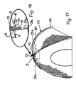
- Such an object may also be of another shape, in particular in longitudinal section approximately oval shape, as in Fig. 23 shown, are clamped when the clamping devices with the rod supports 13, 14 and 13 ', 15' are formed and adjusted accordingly.
Landscapes
- Engineering & Computer Science (AREA)
- Architecture (AREA)
- Civil Engineering (AREA)
- Structural Engineering (AREA)
- Tents Or Canopies (AREA)
Applications Claiming Priority (1)
| Application Number | Priority Date | Filing Date | Title |
|---|---|---|---|
| DE102008045312A DE102008045312A1 (de) | 2008-09-02 | 2008-09-02 | Spannvorrichtung |
Publications (1)
| Publication Number | Publication Date |
|---|---|
| EP2159353A2 true EP2159353A2 (fr) | 2010-03-03 |
Family
ID=41416013
Family Applications (1)
| Application Number | Title | Priority Date | Filing Date |
|---|---|---|---|
| EP20090011135 Withdrawn EP2159353A2 (fr) | 2008-09-02 | 2009-08-31 | Dispositif de mise en tension |
Country Status (2)
| Country | Link |
|---|---|
| EP (1) | EP2159353A2 (fr) |
| DE (1) | DE102008045312A1 (fr) |
Cited By (4)
| Publication number | Priority date | Publication date | Assignee | Title |
|---|---|---|---|---|
| CN102852379A (zh) * | 2011-06-13 | 2013-01-02 | 株式会社友桥 | 帐篷及帐篷连杆调节装置 |
| US20180340347A1 (en) * | 2017-05-29 | 2018-11-29 | Young Sub KIM | Automatic instant tent frame |
| CN109083491A (zh) * | 2018-08-19 | 2018-12-25 | 东莞市史雷帝三维数控科技有限公司 | 一种春游用自动收缩帐篷 |
| CN116378268A (zh) * | 2023-03-31 | 2023-07-04 | 福建华航建设集团有限公司 | 一种石幕墙干挂组件 |
Citations (2)
| Publication number | Priority date | Publication date | Assignee | Title |
|---|---|---|---|---|
| US5046882A (en) | 1989-09-27 | 1991-09-10 | Bae Jin Corporation | Tent frame folding device |
| WO2006038770A1 (fr) | 2004-10-09 | 2006-04-13 | Yook-Hyun Lee | Armature de tente |
Family Cites Families (5)
| Publication number | Priority date | Publication date | Assignee | Title |
|---|---|---|---|---|
| DE361633C (de) * | 1922-10-17 | Josef Ries | Einrichtung zum Auf- und Umklappen der Streben und Fuesse an zusammenlegbaren Stuehlen, Tischen, Gartenschirmen u. dgl. | |
| US4750509A (en) * | 1985-11-25 | 1988-06-14 | Kim Soon Tae | Folding device of a tent-framework |
| GB9021994D0 (en) * | 1990-10-10 | 1990-11-21 | Park Brian W | Device for tensioning structures |
| US6604844B2 (en) * | 1999-06-20 | 2003-08-12 | Richard Hussey | Reconfigurable reflective apparatus |
| IT1314246B1 (it) * | 1999-12-01 | 2002-12-06 | Daniele Caprioli | Bastone da passeggio autoreggente. |
-
2008
- 2008-09-02 DE DE102008045312A patent/DE102008045312A1/de not_active Withdrawn
-
2009
- 2009-08-31 EP EP20090011135 patent/EP2159353A2/fr not_active Withdrawn
Patent Citations (2)
| Publication number | Priority date | Publication date | Assignee | Title |
|---|---|---|---|---|
| US5046882A (en) | 1989-09-27 | 1991-09-10 | Bae Jin Corporation | Tent frame folding device |
| WO2006038770A1 (fr) | 2004-10-09 | 2006-04-13 | Yook-Hyun Lee | Armature de tente |
Cited By (4)
| Publication number | Priority date | Publication date | Assignee | Title |
|---|---|---|---|---|
| CN102852379A (zh) * | 2011-06-13 | 2013-01-02 | 株式会社友桥 | 帐篷及帐篷连杆调节装置 |
| US20180340347A1 (en) * | 2017-05-29 | 2018-11-29 | Young Sub KIM | Automatic instant tent frame |
| CN109083491A (zh) * | 2018-08-19 | 2018-12-25 | 东莞市史雷帝三维数控科技有限公司 | 一种春游用自动收缩帐篷 |
| CN116378268A (zh) * | 2023-03-31 | 2023-07-04 | 福建华航建设集团有限公司 | 一种石幕墙干挂组件 |
Also Published As
| Publication number | Publication date |
|---|---|
| DE102008045312A1 (de) | 2010-03-04 |
Similar Documents
| Publication | Publication Date | Title |
|---|---|---|
| DE3721830C2 (de) | Schirm sowie Abschirmung | |
| DE102011052394B4 (de) | Falt-Reflektor | |
| DE112017005797B4 (de) | Ausfahrbare Standsäule und Zelt umfassend derselben | |
| DE3235857A1 (de) | Teilbare tragbahre | |
| EP0587529A2 (fr) | Dispositif de protection | |
| EP3191771B1 (fr) | Dispositif de maintien pour module solaire placé sur une balustrade de balcon | |
| EP3038859B1 (fr) | Dispositif télescopique | |
| DE2902419C3 (de) | Stativ für optische Geräte, insbesondere Kameras | |
| EP2159353A2 (fr) | Dispositif de mise en tension | |
| EP4064939A1 (fr) | Structure de raccordement de tuyau et kit de meuble | |
| DE2826182A1 (de) | Gestell fuer tische, fahrbare buerowagen u.dgl. | |
| DE2353967C3 (de) | Schirm, insbesondere Gartenschirm | |
| EP2090723B1 (fr) | Structure porteuse pour du matériau plat en particulier pouvant être tendu en tant que corps creux | |
| DE2443042B2 (de) | Transportvorrichtung für Campingliegen | |
| DE60300764T2 (de) | Aufrollbare Beckenabdeckung | |
| DE102023118570B4 (de) | Kopplungsvorrichtung | |
| DE102010060191A1 (de) | Tisch mit einklappbaren Tischbeinen | |
| DE3048862C2 (de) | Federspannvorrichtung zum Vorspannen von Schraubenfedern an Fahrwerksfederungen, insbesondere zum Montieren von Kraftfahrzeugen | |
| DE4227322C1 (en) | Tent rapidly erectable frame with linkage coupled to central suspension - comprises rods secured in releasable holders by distal ends,and tensioning spokes coupled to clamping head | |
| EP0893557A1 (fr) | Ensemble de mâts de tente et dispositif de blocage correspondant | |
| CH711506B1 (de) | Klappmechanismus für einen Tisch. | |
| DE2553166C2 (de) | Vorrichtung zur Verbindung zweier Rohrenden | |
| DE2233342A1 (de) | Teleskopmast | |
| DE19737368A1 (de) | Zeltstangen-Einheit sowie Klemmeinrichtung dafür | |
| DE7807785U1 (de) | Laufrolle mit einer halterung zu ihrer loesbaren befestigung |
Legal Events
| Date | Code | Title | Description |
|---|---|---|---|
| PUAI | Public reference made under article 153(3) epc to a published international application that has entered the european phase |
Free format text: ORIGINAL CODE: 0009012 |
|
| AK | Designated contracting states |
Kind code of ref document: A2 Designated state(s): AT BE BG CH CY CZ DE DK EE ES FI FR GB GR HR HU IE IS IT LI LT LU LV MC MK MT NL NO PL PT RO SE SI SK SM TR |
|
| AX | Request for extension of the european patent |
Extension state: AL BA RS |
|
| STAA | Information on the status of an ep patent application or granted ep patent |
Free format text: STATUS: THE APPLICATION IS DEEMED TO BE WITHDRAWN |
|
| 18D | Application deemed to be withdrawn |
Effective date: 20150303 |