EP2090726A2 - Serrure à goupilles de combinaison de section non circulaires et excentriques pouvant être positionnées par rotation et clé avec des indentations de combinaison difficile à reproduire frauduleusement - Google Patents
Serrure à goupilles de combinaison de section non circulaires et excentriques pouvant être positionnées par rotation et clé avec des indentations de combinaison difficile à reproduire frauduleusement Download PDFInfo
- Publication number
- EP2090726A2 EP2090726A2 EP20090250295 EP09250295A EP2090726A2 EP 2090726 A2 EP2090726 A2 EP 2090726A2 EP 20090250295 EP20090250295 EP 20090250295 EP 09250295 A EP09250295 A EP 09250295A EP 2090726 A2 EP2090726 A2 EP 2090726A2
- Authority
- EP
- European Patent Office
- Prior art keywords
- combination
- pins
- indentations
- pin
- key
- Prior art date
- Legal status (The legal status is an assumption and is not a legal conclusion. Google has not performed a legal analysis and makes no representation as to the accuracy of the status listed.)
- Withdrawn
Links
- 238000007373 indentation Methods 0.000 title claims abstract description 166
- 230000000295 complement effect Effects 0.000 claims abstract description 4
- 230000001788 irregular Effects 0.000 claims description 26
- 230000000873 masking effect Effects 0.000 claims description 10
- 238000006073 displacement reaction Methods 0.000 claims description 8
- 230000007704 transition Effects 0.000 claims description 8
- 238000005520 cutting process Methods 0.000 description 11
- 238000000034 method Methods 0.000 description 9
- 230000015572 biosynthetic process Effects 0.000 description 4
- 230000008030 elimination Effects 0.000 description 4
- 238000003379 elimination reaction Methods 0.000 description 4
- 230000000007 visual effect Effects 0.000 description 4
- 230000009977 dual effect Effects 0.000 description 2
- 230000008878 coupling Effects 0.000 description 1
- 238000010168 coupling process Methods 0.000 description 1
- 238000005859 coupling reaction Methods 0.000 description 1
- 238000005336 cracking Methods 0.000 description 1
- 230000007547 defect Effects 0.000 description 1
- 230000002950 deficient Effects 0.000 description 1
- 238000009826 distribution Methods 0.000 description 1
- 230000002349 favourable effect Effects 0.000 description 1
- 238000003780 insertion Methods 0.000 description 1
- 230000037431 insertion Effects 0.000 description 1
- 238000005304 joining Methods 0.000 description 1
- 238000003754 machining Methods 0.000 description 1
- 230000007257 malfunction Effects 0.000 description 1
- 238000004519 manufacturing process Methods 0.000 description 1
- 238000002360 preparation method Methods 0.000 description 1
- 230000003313 weakening effect Effects 0.000 description 1
Images


Classifications
-
- E—FIXED CONSTRUCTIONS
- E05—LOCKS; KEYS; WINDOW OR DOOR FITTINGS; SAFES
- E05B—LOCKS; ACCESSORIES THEREFOR; HANDCUFFS
- E05B27/00—Cylinder locks or other locks with tumbler pins or balls that are set by pushing the key in
- E05B27/0003—Details
- E05B27/0017—Tumblers or pins
- E05B27/0021—Tumblers or pins having movable parts
-
- E—FIXED CONSTRUCTIONS
- E05—LOCKS; KEYS; WINDOW OR DOOR FITTINGS; SAFES
- E05B—LOCKS; ACCESSORIES THEREFOR; HANDCUFFS
- E05B19/00—Keys; Accessories therefor
- E05B19/0017—Key profiles
- E05B19/0023—Key profiles characterized by variation of the contact surface between the key and the tumbler pins or plates
-
- E—FIXED CONSTRUCTIONS
- E05—LOCKS; KEYS; WINDOW OR DOOR FITTINGS; SAFES
- E05B—LOCKS; ACCESSORIES THEREFOR; HANDCUFFS
- E05B19/00—Keys; Accessories therefor
- E05B19/0017—Key profiles
- E05B19/0035—Key profiles characterized by longitudinal bit variations
-
- E—FIXED CONSTRUCTIONS
- E05—LOCKS; KEYS; WINDOW OR DOOR FITTINGS; SAFES
- E05B—LOCKS; ACCESSORIES THEREFOR; HANDCUFFS
- E05B27/00—Cylinder locks or other locks with tumbler pins or balls that are set by pushing the key in
- E05B27/0003—Details
- E05B27/0017—Tumblers or pins
-
- E—FIXED CONSTRUCTIONS
- E05—LOCKS; KEYS; WINDOW OR DOOR FITTINGS; SAFES
- E05B—LOCKS; ACCESSORIES THEREFOR; HANDCUFFS
- E05B27/00—Cylinder locks or other locks with tumbler pins or balls that are set by pushing the key in
- E05B27/0039—Cylinder locks or other locks with tumbler pins or balls that are set by pushing the key in with pins which slide and rotate about their axis
-
- E—FIXED CONSTRUCTIONS
- E05—LOCKS; KEYS; WINDOW OR DOOR FITTINGS; SAFES
- E05B—LOCKS; ACCESSORIES THEREFOR; HANDCUFFS
- E05B17/00—Accessories in connection with locks
- E05B17/007—Devices for reducing friction between lock parts
-
- E—FIXED CONSTRUCTIONS
- E05—LOCKS; KEYS; WINDOW OR DOOR FITTINGS; SAFES
- E05B—LOCKS; ACCESSORIES THEREFOR; HANDCUFFS
- E05B19/00—Keys; Accessories therefor
- E05B19/0017—Key profiles
- E05B19/0041—Key profiles characterized by the cross-section of the key blade in a plane perpendicular to the longitudinal axis of the key
- E05B19/0052—Rectangular flat keys
- E05B19/0058—Rectangular flat keys with key bits on at least one wide side surface of the key
-
- Y—GENERAL TAGGING OF NEW TECHNOLOGICAL DEVELOPMENTS; GENERAL TAGGING OF CROSS-SECTIONAL TECHNOLOGIES SPANNING OVER SEVERAL SECTIONS OF THE IPC; TECHNICAL SUBJECTS COVERED BY FORMER USPC CROSS-REFERENCE ART COLLECTIONS [XRACs] AND DIGESTS
- Y10—TECHNICAL SUBJECTS COVERED BY FORMER USPC
- Y10T—TECHNICAL SUBJECTS COVERED BY FORMER US CLASSIFICATION
- Y10T70/00—Locks
- Y10T70/70—Operating mechanism
- Y10T70/7441—Key
- Y10T70/7729—Permutation
- Y10T70/7734—Automatically key set combinations
Definitions
- This invention relates to a lock of the type which for the opening combination uses pin-counterpin sets which are located in seatings or housings which are determined by orifices provided through the stator and the rotor of the cylinder which is activated by the turn of a key the shaft of which is inserted in said rotor.
- This invention relates to a system for cutting, so as to make them difficult to reproduce fraudulently, the combination indentations in blades of keys for locks which use pin-counterpin sets established in respective combination seatings which are aligned in one or two rows in the body of the cylinder of the lock which may be of the same type as described in Spanish Patent P- 200800309 .
- Cylinders which comprise a rotor and stator and with housing orifices of combination pins which go through [the] stator and rotor and in each of the seatings or orifices are housed a pin and a counterpin (or drive pin).
- each orifice uses respective cylindrical pins (and their respective counterpins) which, therefore, can turn freely therein without having a fixed and specific rotatory position, which requires their tip to be centred according to its turning axis to ensure its operating performance with respect to the indentation cut for the purpose in the shaft of the key.
- Cylinders are also known in which said orifices have a transversal section form such that it impedes its turn, that is to say, that they have a fixed rotatory position and the pin-counterpin sets can only move up and down along the orifice thereof.
- cylinders are also known which use revolving pins with various forms of tip in contact with the key; this makes copying the key difficult, but at the expense of there being only a single valid pin for each form and height of the cut of the key.
- teethed keys which have the main combination cuts in the thin face of the blade and possibly another in the wide face (in the form of a point, step or channel) to add some additional condition of greater anti-copying or anti-opening security of the cylinder; when it is the wide face which has the cuts the key is called "flat".
- these fixed and known positions of the cuts of the blade enable the use of fraudulent opening procedures which are based on the preparation of false keys which succeed in opening the cylinder by means of techniques such as "bumping", consisting in repeatedly knocking the false key inserted in the cylinder, at the same time as applying rotational pressure on it, so that a moment is encountered in which all the pins together are raised against the spring thereof further away from the plane of rotation of the rotor of the cylinder, enabling the latter to turn in the direction of opening of the cylinder.
- "bumping" consisting in repeatedly knocking the false key inserted in the cylinder, at the same time as applying rotational pressure on it, so that a moment is encountered in which all the pins together are raised against the spring thereof further away from the plane of rotation of the rotor of the cylinder, enabling the latter to turn in the direction of opening of the cylinder.
- this invention proposes a lock with combination pins of non-circular section and excentricity capable of being positioned in rotation, according to which the seatings or housing orifices for the pin-counterpin sets are aligned according to the longitudinal median plane of the cylinder of the lock, although the invention can also be implemented on double row cylinders, and are bored with a transversal section which is not circular but circumscribed to a cylinder the diameter of which has sliding adjustment with regard to that of conventional revolving pins which do not have a marked rotatory position, and in at least one of these same orifices in the rotor two semi-pins are housed together, abutting each other, which are provided with respective excentric tips and which in their combined outline are complementary with regard to said transversal section of the orifice which is provided for the purpose through the stator and the rotor of the cylinder reaching the key entry channel in said rotor, and of which the excentric tips of the pair of semi-pins housed in a same
- any other type of non-revolving type of pin can be mounted, provided that the outline (except for the paraxial projections) has an operating diameter corresponding to that of a housing in a conventional cylinder; for example, pins in one piece with two heads at a different height, or pins in one piece with a variable position excentric tip (for example, each 45° and at two or more different distances from the axis of the pin), or with a specially machined tip for operating on one or the other, including both together, of two rows of cuts of the key.
- toothed keys and flat keys which, moreover, may have two, three or more rows of cuts, which, furthermore, can present different distances to the head of the key, in clear contrast with what is currently normal: that this distance is fixed.
- stator and rotor of the cylinder of the lock according to the invention are totally interchangeable with those of cylinders already known to exist on the market.
- stator and cylinder rotors existing on the market can be easily adapted to the new system simply by adding a broach of the housings with the form of the new pins, basically with respect to the forming of the corners provided for the coupling of the paraxial projections intended to impede the turning of these new pins, marking the specific fixed rotatory working position thereof.
- the lock according to the invention enables more modular and versatile production, since the decision on the pin to be mounted in each seating can be made at the time it is mounted, thus allowing any of the types according to the invention to be selected or, also, combining them with conventional ones when the application demands a lower level of requirements, which offers the additional feature of much greater levels of security and sophistication than current mid-level and medium-priced but very widely used locks.
- This invention proposes a lock key with combination indentations difficult to reproduce fraudulently, of the type which have at least one row of combination seatings which operate with the pin-counterpin sets housed in the orifices of the cylinder, comprising a stator and a rotor, and designating a median plane of pins and counterpins to the plane which contains the axes of the cylindrical part thereof and which would also be the plane which would contain the combination indentations of the key if the pins were not off-centre on their active tip, characterised in that , in the blade of the key an irregular sinuous channel is cut with respect to the median plane of pins, this channel in each transversal section has a variable width and, at least, a variable depth of independent size between them, the irregular sinuous channel of which has a plurality of combination indentations cut at the bottom with a dimension which is a combined function of a plurality of so-called combination parameters, master keying parameters, parameters of transition between longitudinally successive combination indentations and parameters of masking
- another special feature of the invention is that, in relation to each of the pin-counterpin sets which operate on the combination seatings of the cylinder, the blade is capable of having one or more of a plurality of potential combination indentations which are cut in a variable position and which with different radial distances are contained in a circle which is centred with the operational axis of a plurality of said pin-counterpin sets where the pins have conveniently off-centre tips and which, in each combination seating, are capable of operating selectively with one of these potential combination indentations;
- a form of embodiment in this respect is that, for each combination seating of the cylinder, the potential combination indentations cut at the bottom of the irregular sinuous channel, are arranged in the form of at least a first crown, preferably numbering eight, with a displacement of 45° between them, and the centres of which comprise between a minimum diameter of 2mm and a maximum diameter of 5mm; another form of embodiment is the existence of a second crown of potential combination in
- the pin in each combination seating the pin can be acting on any one of the potential combination indentations around the operational axis thereof, so by looking at the cylinder through the key entry groove, the view of the pin is not indicative of the place where the combination indentation which is acting as the effective combination indentation will be; also, neither does the view of the key clarify anything in this respect, since there are millions of variations possible and very similar to one another.
- Another distinguishing property of the invention comes from the sinuous trajectory which in the manoeuvre of inserting the key covers from start to finish the consecutive combination indentations, such that the latter remain linked by means of said drive track inclined accordingly, through machined segments of elimination of material of the blade, enabling the transition between them in adjusting for the correct introduction and functioning of the key in the cylinder.
- Another special feature of the invention is that in one or more of the combination seatings existing in the irregular sinuous channel and in relation to at least one of the pin-counterpin sets which operate in the combination seatings of the cylinder, as well as the combination indentation, in this irregular sinuous channel of the blade there exist, at least, two combination indentations which have a different depth; preferably, in this respect the use of two combination indentations of different depth is provided for, only one of which operates with the excentric tip (8a) of the pin, which, in the direction of introduction of the blade into the cylinder, is linked with the preceding theoretical combination indentations by means of a single segment of the drive track inclined accordingly.
- the invention also contemplates that only one of these combination indentations operates with the excentric tip (8a) of the pin, while the other is capable of operating with the excentric tip (8a) of a pin belonging to another cylinder provided with another opening combination which is compatible with the same key, and in the direction of introduction of the blade into the cylinder, these two combination indentations are linked with the combination indentations of the preceding and following combination seatings by means of respective segments of a forked drive track inclined accordingly, or, of a single segment of the drive track inclined accordingly which starts from an intermediate place between the two combination indentations of the current combination seating.
- This capability of the invention enables a dual function: on the one hand, that of the two combination indentations (non-combination indentation) which does not work with the excentric pin and which, therefore, does not participate in the opening combination cut in the blade in relation to a particular cylinder, performs the function of masking the valid opening combination thereof, thereby misleading a person who may be attempting to breach the cylinder; moreover, this non-combination indentation for this particular cylinder can act as a combination indentation for opening another cylinder with this same key blade, which performs a function of master keying which, furthermore, proves favourable in the functional capacity thereof, given the enormous number of possible combinations of the proposed key.
- the cuts of the keys are combined conventional cuts, cuts with special cutters, cuts with special trajectories, cuts with variable depths, cuts with indentations and trajectories which are totally or partially off-centre, channels with a trajectory joining indentations with a component which is determined as necessary for the smooth introduction of the key and for establishing the opening code or combination for the pins of the cylinder, plus a mastering trajectory which is made with a special tool to achieve configuration of walls for the irregular channel which does not allow reliable data to be obtained for falsifying the key, giving rise to a visual profile which does not allow the depth of the cut to be read.
- the picklock method is rendered impracticable, due to the large number of possible positions of the tips of the pins; the design of sets of "half keys" (jargon) which try to force the cylinder by their insertion one after another is also rendered futile, due to the millions of possible keys for a cylinder according to the invention; they also offer special security against the aforementioned technique of "bumping".
- the content of the invention can also be applied to toothed keys, not just to flat keys, although for the latter the significance of the invention is much greater.
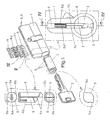
- FIGS. 1 and 1A illustrate the preferred configuration of the semi-pins (6), the mounting thereof in the cylinder (1-2), the form of the transversal section of the orifice (5) of the seating and the internal arrangement in the cylinder (see the transversal and longitudinal sections thereof, and figures 2 and 3 ), where each semi-pin (6) has a counterpin (6c) associated with it which is mounted against a spring (6d).
- said excentric tips (6a) of the pair of semi-pins (6) of a same orifice (5) are capable of operating in combination indentations belonging to a same or to two different rows of cuts provided in two parallel edges of a same flanked key (3); as in addition ( figures 25 to 27 ) said excentric tips (6a) of the pair of semi-pins (6) of a same orifice (5) are capable of operating in combination indentations belonging to a same or to two different rows of cuts provided in a larger face of the shaft of a flat key (4).
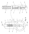
- FIG. 6 An alternative embodiment is the one illustrated by figures 6 to 11 , where the semi-pins (6) of each orifice (5) have a different length and, with the exception of their paraxial projections (6b), the two semi-pins (6) together form a cylindrical outline with the diameter of a pin of the conventional type and are abutting each other according to a sinusoidal plane which spans a complete period; in the same way as in the preceding configuration, according to a preferred embodiment of the invention, said paraxial projections (6b) of the pair of semi-pins (6) are mutually in diametric opposition and preferably at 45° to the longitudinal plane which contains the axes of the active respective excentric tips (6a) thereof.
- each semi-pin (6) has a counterpin (6c) associated with it which is mounted against a spring (6d).
- FIG. 12 to 16 Another embodiment of the invention ( figures 12 to 16 ) consists in the semi-pins (6) of a same orifice (5) being integrated in a one-piece pin (7) provided with two excentric tips (7a) which are capable of operating in combination indentations belonging to a same or to two different rows of cuts provided in the shaft of the key; with the exception of the paraxial projections (7b), the one-piece pin (7) has a cylindrical periphery with the diameter of a pin of the conventional type and has its two excentric tips (7a) which can be staggered in a longitudinal direction or an excentric tip (8a) in angular positions (8c) with regard to the rotational axis of the pin; according to a preferred embodiment, said paraxial projections (7b) of the one-piece pin are ( figures 14 and 15 ) in mutual diametric opposition and preferably at 45° to the longitudinal plane which contains the axes of said excentric tips (7a).
- said excentric tips (7a) of the one-piece pin (7) are capable of operating in combination indentations belonging to a same or to two different rows of cuts provided in two parallel edges ( figure 16 ) of a same flanked key (3); or also, said excentric tips (7a) of the one-piece pin (7) are capable of operating in combination indentations belonging to a same or to two different rows of cuts provided in a larger face of the shaft of a flat key (4).
- each one-piece pin (7) has a counterpin (7c) associated with it which is mounted against a spring (7d).
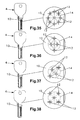
- Figures 17 to 24 and 28 show an orientable one-piece pin (8) and with a single excentric tip (8a) as an illustration of the large variety of types of pin which can be used interchangeably in the lock system according to the invention; in this orientable one-piece pin (8) its excentric tip (8a) is capable of operating on any of the indentations grouped in a two by two square of the flat key (4) of figure 27 simply by mounting it in one or other of the orientations shown in the pairs of figures 17-18, 19-20, 21-22 and 23-24 ; as is obvious, this orientable one-piece pin (8), like the other types described above, can also operate in relation to the cuts which, for illustrative purposes, are shown in the flat keys (4) of figures 25, 26 and 29 .
- the excentric tips (6a, 7a, 8a) are capable of operating in combination indentations belonging to a same or to multiple different rows of cuts provided in a larger face of the shaft of a flat key (4).
- the blade (10) is capable of having one or more of a plurality of potential combination indentations (12) which are cut in a variable position and which with different radial distances are contained in a circle (14) which is centred with the operational axis of a plurality of said pin-counterpin sets (8-7c) where the pins (8) have conveniently off-centre tips and which, in each combination seating, are capable of operating selectively with one of these potential combination indentations (12).
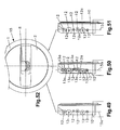
- each combination seating the potential combination indentations (12) cut at the bottom of the irregular sinuous channel (11), are arranged ( figure 32 ) in the form of at least a first crown, preferably numbering eight, with a displacement of 45° between them, and the centres of which comprise between a minimum diameter of 2mm and a maximum diameter of 5mm; the existence of a second crown of potential combination indentations (12) being provided for which is defined by the interior of said first crown and which is similar to the latter in the number and displacement of indentations; in figure 32 the more general case of arranging the two crowns of potential combination indentations (12) is represented, but, bearing in mind that the essence of the Patent is not the particular distribution thereof, but the manner of using them in conjunction with the irregular sinuous channel (11) and the drive track inclined accordingly (13), within the scope of this Patent any arrangement of potential combination indentations (12) is included, for example, those included in figures 35 to 38 .
- figures 39 to 42 show some based on using only four of the potential combination indentations (12) ( figure 38 ) [those which in the containing circle (14) are in the clockwise positions of 45° and 135°, and those diametrically opposite thereto] and with only five depths or heights of cut of each combination indentation (12) (it is quite usual to work with seven possible heights).
- the blades (10) are formed with simple cuts, where as stated only alternative positions and heights of the combination indentations (12) are used, the profile of the cut being viewable in the enlarged detail of figure 43 .
- Another special feature of the invention is that, in the drive track inclined accordingly (13) of the irregular sinuous channel (11), the consecutive combination indentations (12) are linked by means of machined segments (13a) of elimination of material of the blade (10) which enable the transition between them in adjusting the key's correct introduction and functioning in the cylinder (15).
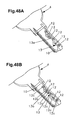
- a further step in doing the cutting according to the invention is that shown in figure 45 , showing an already formed irregular sinuous channel (11) with the profusion of widths and depths made randomly and freely, enabling large widths to co-exist with large or small depths, and vice versa, with the particular feature that a width and depth of channel for a combination seating does not allow it to be known where the combination indentation (12), on which the tip of the pin will act, will be.
- the irregular sinuous channel (11) of figure 45 corresponds to what is known as an "ideal” cut and is defined by segments on the basis of which it is possible to adjust curves by means of mathematical interpolation by so-called “spline” methods which make it possible to "smooth” the outline achieving smooth fits between contiguous machined segments (13a) which are initially rectilinear; this leads to the configuration of figure 46 .
- Another particular feature of the invention is that, in relation to at least one of the pin-counterpin sets (8-7c) which operate in the combination seatings of the cylinder (15), in the irregular sinuous channel (11) of the blade (10) there exist, at least, two combination indentations (12) which have a different depth.
- a preferred embodiment in this respect is to have two combination indentations (12) which have a different depth.
- the invention contemplates that, in relation to the pin-counterpin set (8-7c) of the combination seatings of the cylinder (15) which in the blade (10) are provided with two combination indentations (12) with different depths, only one of these operates with the excentric tip (8a) of the pin (8), which, in the direction of introduction of the blade (10) into the cylinder (15), is linked with the preceding combination indentation (12) by means of a single segment (13a) of the drive track inclined accordingly (13); likewise, according to the invention, in relation to the pin-counterpin set (8-7c) of the combination seatings of the cylinder (15) which in the blade (10) are provided with two combination indentations (12) with different depths, one of these operates with the excentric tip (8a) of the pin (8), while the other is capable of operating with the excentric tip (8a) of a pin (8) belonging to another cylinder (15) provided with another opening combination which is compatible with the same key, and in the direction of introduction of the blade (10) into the cylinder (15).
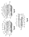
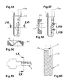
- FIG 34 This arrangement is illustrated in figure 34 , where it can be seen that the pin (8) has its tip sitting in the combination indentation (12) and that there is a non-combination indentation (12c) which can have a function of masking the opening code or which can be used for master keying, using the same key blade (10) to open another cylinder (15); other graphical representations in this respect are those of figures 48 (A and B) and 49 to 52, where figures 49 (simple cut), 50 (decrested cut) and 51 (masked cut, the one providing the new property), in relation to figure 52 , highlight the fact that looking at the key entry groove we see only the front pin (8), without being able to tell the direction of its tip and, much less, how those which are hidden behind it are oriented.
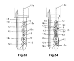
- figures 53 and 54 show a blade (10) with the same opening combination; the first, referring to a simple masked cut, and the second, to the same masked but decrested cut, the latter enabling one to appreciate the difficulty it presents in making a fraudulent copy, including a legal copy, as set out above, it requires very special equipment and resources, as it cannot be made with the means currently in use.
- Another particular feature of the invention is that the potential combination indentations (12) are capable of operating with pins belonging to pin-counterpin sets (8-7c) which incorporate elements of master keying, it being necessary to point out in this respect that the capabilities of master keying and combination locks are thereby enhanced.
- the invention is also applicable to keys with combination indentations in their flank known as toothed keys with the logical limitation that it imposes the narrow thickness available for forming the irregular sinuous channel (11);
- figure 59 represents a toothed key (3) according to the invention, which, as shown in figure 60 , is specific to the case in that the irregular sinuous channel (11), with the non-rectilinear trajectory which may be chosen, has two different depths in a section in which these depths are in two equal halves of the thickness of the blade (10).
- the plurality of potential combination indentations (12) which are cut in a variable position and which with different radial distances are also implemented on the flank of so-called toothed keys thereby establishing, for each theoretical arrangement of coded pin, two possible areas of right and left cut, in the direction of said flank of the key and for each one of them, at least three other different positions as a function of the relative position of the axis of the tip of the pin which operates on said indentation with respect to the longitudinal axis of said pin: forward, coinciding or behind.
- Partial implementation of the invention is provided for more basic or economic implementations, as well as the application thereof to all the combination positions of keys or only to part thereof.
Landscapes
- Lock And Its Accessories (AREA)
- Surgical Instruments (AREA)
- Pinball Game Machines (AREA)
- Manufacture Of Motors, Generators (AREA)
Priority Applications (1)
| Application Number | Priority Date | Filing Date | Title |
|---|---|---|---|
| EP12172455.3A EP2511455B1 (fr) | 2008-02-05 | 2009-02-05 | Verrou avec broche de combinaison de section non circulaire et excentricité pouvant être positionné en rotation et clé de verrou dotée d'une indentation de combinaison difficile à reproduire frauduleusement |
Applications Claiming Priority (2)
| Application Number | Priority Date | Filing Date | Title |
|---|---|---|---|
| ES200800309A ES2337222B1 (es) | 2008-02-05 | 2008-02-05 | "cerradura con pitones de combinacion de seccion no circular y excentricidad posicionable en rotacion". |
| ES200803517A ES2368543B1 (es) | 2008-12-11 | 2008-12-11 | Llave de cerradura con huellas de combinación de difícil reproducción fraudulenta. |
Related Child Applications (1)
| Application Number | Title | Priority Date | Filing Date |
|---|---|---|---|
| EP12172455.3A Division EP2511455B1 (fr) | 2008-02-05 | 2009-02-05 | Verrou avec broche de combinaison de section non circulaire et excentricité pouvant être positionné en rotation et clé de verrou dotée d'une indentation de combinaison difficile à reproduire frauduleusement |
Publications (2)
| Publication Number | Publication Date |
|---|---|
| EP2090726A2 true EP2090726A2 (fr) | 2009-08-19 |
| EP2090726A3 EP2090726A3 (fr) | 2011-11-02 |
Family
ID=40845829
Family Applications (2)
| Application Number | Title | Priority Date | Filing Date |
|---|---|---|---|
| EP20090250295 Withdrawn EP2090726A3 (fr) | 2008-02-05 | 2009-02-05 | Serrure à goupilles de combinaison de section non circulaires et excentriques pouvant être positionnées par rotation et clé avec des indentations de combinaison difficile à reproduire frauduleusement |
| EP12172455.3A Active EP2511455B1 (fr) | 2008-02-05 | 2009-02-05 | Verrou avec broche de combinaison de section non circulaire et excentricité pouvant être positionné en rotation et clé de verrou dotée d'une indentation de combinaison difficile à reproduire frauduleusement |
Family Applications After (1)
| Application Number | Title | Priority Date | Filing Date |
|---|---|---|---|
| EP12172455.3A Active EP2511455B1 (fr) | 2008-02-05 | 2009-02-05 | Verrou avec broche de combinaison de section non circulaire et excentricité pouvant être positionné en rotation et clé de verrou dotée d'une indentation de combinaison difficile à reproduire frauduleusement |
Country Status (4)
| Country | Link |
|---|---|
| US (1) | US20090193862A1 (fr) |
| EP (2) | EP2090726A3 (fr) |
| ES (1) | ES2704623T3 (fr) |
| PT (1) | PT2511455T (fr) |
Cited By (4)
| Publication number | Priority date | Publication date | Assignee | Title |
|---|---|---|---|---|
| WO2012177493A1 (fr) * | 2011-06-19 | 2012-12-27 | Mul-T-Lock Technologies Ltd. | Ensemble de serrure à répulsion magnétique |
| CN104314374A (zh) * | 2014-10-15 | 2015-01-28 | 冯伟坚 | 一种锁芯及适配钥匙 |
| EP3015628A1 (fr) * | 2014-10-27 | 2016-05-04 | Metalurgica Cerrajera de Mondragon, S.A. | Dispositif de barillet pour serrure doté de goupilles combinées |
| EP4431682A1 (fr) * | 2023-03-16 | 2024-09-18 | Jiangyin Orient Gangsheng Metal Products Co., Ltd | Noyau de verrouillage ayant des broches doubles dans un trou |
Families Citing this family (10)
| Publication number | Priority date | Publication date | Assignee | Title |
|---|---|---|---|---|
| US8950226B2 (en) * | 2011-10-12 | 2015-02-10 | Moshe Dolev | Cylinder lock assembly with non-rotating elements |
| CN102913058B (zh) * | 2012-10-10 | 2016-03-16 | 陈照林 | 一种锁头的防撬空转结构 |
| IL223616A0 (en) * | 2012-12-13 | 2013-02-03 | Asher Haviv | Locking system and key therefor |
| CN103132787B (zh) * | 2013-02-19 | 2015-09-09 | 陈仁多 | 利用原钥匙开启反锁保险闩功能锁芯 |
| SE537246C2 (sv) * | 2013-03-20 | 2015-03-17 | Winloc Ag | Cylinderlås- och nyckelkombination med dubbelt tillhållaraggregat i låset |
| US20140352374A1 (en) * | 2013-04-03 | 2014-12-04 | Li Szu SHEN | Lock cylinder having enhanced burglarproof effect |
| CN104074399B (zh) * | 2014-07-03 | 2016-04-13 | 刘楚 | 防技术开启的锁头 |
| CN106368515A (zh) * | 2016-08-30 | 2017-02-01 | 何勤 | 一种双保险锁及其钥匙 |
| WO2019180497A1 (fr) * | 2018-03-17 | 2019-09-26 | Joshi Prabhakar Anant | Serrure à mortaise dotée d'un profil de fente à clé fermée |
| CN112177439B (zh) * | 2020-08-31 | 2021-11-09 | 苏州市东挺河智能科技发展有限公司 | 一种双锁芯式机械密码锁及其防护装置 |
Citations (4)
| Publication number | Priority date | Publication date | Assignee | Title |
|---|---|---|---|---|
| EP0625624A1 (fr) * | 1993-05-20 | 1994-11-23 | Gerd Dipl.-Ing. Niederdrenk | Serrure cylindrique |
| AT2535U1 (de) * | 1997-10-31 | 1998-12-28 | Evva Werke | Schliesszylinder und flachschlüssel |
| US5894750A (en) * | 1996-04-22 | 1999-04-20 | Liaw; Shyan-Tsair | Lock |
| DE102006044106A1 (de) * | 2006-09-20 | 2008-04-03 | Dom Sicherheitstechnik Gmbh & Co Kg | Aus zwei parallel zueinander verlaufenden Steuerflanken aufweisenden Schlüssel und Zylinderschloss bestehendes Schließsystem |
Family Cites Families (22)
| Publication number | Priority date | Publication date | Assignee | Title |
|---|---|---|---|---|
| BE664635A (fr) * | 1965-05-28 | 1900-01-01 | ||
| CH638585A5 (de) * | 1979-04-24 | 1983-09-30 | Ernst Keller | Schliessanlage mit einer vielzahl voneinander abweichender schliessungsmoeglichkeiten. |
| DE3136314A1 (de) * | 1981-09-12 | 1983-03-24 | Fa. Wilhelm Karrenberg, 5620 Velbert | Flachschluessel fuer schliesszylinder |
| DE3375037D1 (en) * | 1983-02-04 | 1988-02-04 | Evva Werke | Cylinder lock with a cylinder housing and a cylinder core, as well as a key |
| US4635455A (en) * | 1985-07-19 | 1987-01-13 | Medeco Security Locks, Inc. | Cylinder lock |
| DE8534096U1 (de) * | 1985-12-04 | 1986-01-30 | Percic, Mladen, 6000 Frankfurt | Zylinderschloß mit einer Nachschließsicherung |
| US4998426A (en) * | 1987-06-08 | 1991-03-12 | Genakis Joseph M | Cylinder lock |
| AT389559B (de) * | 1988-03-31 | 1989-12-27 | Evva Werke | Flachschluessel fuer zylinderschloesser sowie zugehoeriges zylinderschloss |
| DE3827687A1 (de) * | 1988-08-16 | 1990-02-22 | Dom Sicherheitstechnik | Schliessvorrichtung |
| US5419168A (en) * | 1991-10-24 | 1995-05-30 | Medeco Security Locks, Inc. | Hierarchical cylinder lock and key system |
| DE9307547U1 (de) * | 1993-05-20 | 1993-10-21 | Niederdrenk, Gerd, Dipl.-Ing., 5620 Velbert | Schließzylinder |
| IT1268687B1 (it) * | 1994-12-27 | 1997-03-06 | Silca Spa | Unita' di chiave e serratura a cilindro |
| US5943890A (en) * | 1996-10-31 | 1999-08-31 | Medeco Security Locks, Inc. | Cylinder lock and key assembly and hierarchical system therefor |
| ITTO980491A1 (it) * | 1998-06-05 | 1999-12-05 | Mottura Serrature Di Sicurezza | Serratura a cilindro. |
| US6105404A (en) * | 1998-06-30 | 2000-08-22 | Medeco Security Locks, Inc. | Squiggle keys and cylinder locks for squiggle keys |
| US6257033B1 (en) * | 1999-03-08 | 2001-07-10 | Moshe Dolev | Cylinder lock with rotatable pins |
| SE524645C2 (sv) * | 2002-01-23 | 2004-09-14 | Winloc Ag | Kombination av högsäkerhetslås och nyckelblad |
| IL153068A (en) * | 2002-11-24 | 2010-12-30 | Dany Markbreit | Backward compatible lock system, key blanks and keys therefor |
| EP1635012A3 (fr) * | 2004-09-01 | 2009-06-17 | Alpha Corporation | Serrure cylindrique |
| AT501706B1 (de) * | 2005-04-12 | 2007-01-15 | Evva Werke | Flachschlüssel sowie zugehöriges zylinderschloss |
| SE528842C2 (sv) * | 2005-08-05 | 2007-02-27 | Winloc Ag | Lås- och nyckelsystem med förbättrade tillhållare i låset |
| US7594580B2 (en) * | 2006-01-30 | 2009-09-29 | Lab Security Systems Corporation | Lock pin decoding apparatus |
-
2009
- 2009-02-01 US US12/363,770 patent/US20090193862A1/en not_active Abandoned
- 2009-02-05 EP EP20090250295 patent/EP2090726A3/fr not_active Withdrawn
- 2009-02-05 PT PT12172455T patent/PT2511455T/pt unknown
- 2009-02-05 ES ES12172455T patent/ES2704623T3/es active Active
- 2009-02-05 EP EP12172455.3A patent/EP2511455B1/fr active Active
Patent Citations (4)
| Publication number | Priority date | Publication date | Assignee | Title |
|---|---|---|---|---|
| EP0625624A1 (fr) * | 1993-05-20 | 1994-11-23 | Gerd Dipl.-Ing. Niederdrenk | Serrure cylindrique |
| US5894750A (en) * | 1996-04-22 | 1999-04-20 | Liaw; Shyan-Tsair | Lock |
| AT2535U1 (de) * | 1997-10-31 | 1998-12-28 | Evva Werke | Schliesszylinder und flachschlüssel |
| DE102006044106A1 (de) * | 2006-09-20 | 2008-04-03 | Dom Sicherheitstechnik Gmbh & Co Kg | Aus zwei parallel zueinander verlaufenden Steuerflanken aufweisenden Schlüssel und Zylinderschloss bestehendes Schließsystem |
Cited By (5)
| Publication number | Priority date | Publication date | Assignee | Title |
|---|---|---|---|---|
| WO2012177493A1 (fr) * | 2011-06-19 | 2012-12-27 | Mul-T-Lock Technologies Ltd. | Ensemble de serrure à répulsion magnétique |
| US8997538B2 (en) | 2011-06-19 | 2015-04-07 | Mul-T-Lock Technologies Ltd. | Magnetically repelling lock assembly |
| CN104314374A (zh) * | 2014-10-15 | 2015-01-28 | 冯伟坚 | 一种锁芯及适配钥匙 |
| EP3015628A1 (fr) * | 2014-10-27 | 2016-05-04 | Metalurgica Cerrajera de Mondragon, S.A. | Dispositif de barillet pour serrure doté de goupilles combinées |
| EP4431682A1 (fr) * | 2023-03-16 | 2024-09-18 | Jiangyin Orient Gangsheng Metal Products Co., Ltd | Noyau de verrouillage ayant des broches doubles dans un trou |
Also Published As
| Publication number | Publication date |
|---|---|
| EP2511455B1 (fr) | 2018-11-07 |
| PT2511455T (pt) | 2019-02-12 |
| US20090193862A1 (en) | 2009-08-06 |
| EP2511455A1 (fr) | 2012-10-17 |
| ES2704623T3 (es) | 2019-03-19 |
| EP2090726A3 (fr) | 2011-11-02 |
Similar Documents
| Publication | Publication Date | Title |
|---|---|---|
| EP2511455B1 (fr) | Verrou avec broche de combinaison de section non circulaire et excentricité pouvant être positionné en rotation et clé de verrou dotée d'une indentation de combinaison difficile à reproduire frauduleusement | |
| JP4446886B2 (ja) | 安全錠用キー及び錠シリンダー | |
| AU2009260335B2 (en) | Lock, key blank, and key of a hierarchical lock system | |
| US9103139B2 (en) | Key having movable members and locking system | |
| US10890011B2 (en) | Cylinder lock and key system | |
| WO1993012314A1 (fr) | Ensemble serrure a barillet et cle, cle adaptee a cette serrure et procede d'elaboration de la cle a partir d'une ebauche | |
| EP3366871A1 (fr) | Système de serrure et clé à barillet | |
| CN1366571A (zh) | 防撬转动钥匙和闭锁系统 | |
| AU2022345413A1 (en) | Key, lock system, lock cylinder and production method | |
| CH716812B1 (de) | Schlüsselrohling, Schlüssel, Zylinderschloss und Verfahren zur Herstellung eines Schlüsselrohlings und eines Schlüssels. | |
| US5688085A (en) | Apparatus for rebroaching a lock assembly and a lock assembly made using said apparatus | |
| EP2390031B1 (fr) | Procédé de profilage des faces larges d'une clé plate réversible et clé plate réversible | |
| EP3822433B1 (fr) | Clé, serrure à cylindre, système et méthode | |
| US6755062B2 (en) | Anti-pick mogul deadlock | |
| CA2529716C (fr) | Serrure rotative et cle | |
| CN103628742A (zh) | 一种叶片锁锁芯和钥匙 | |
| CN102493716B (zh) | 一种锁头 | |
| ES2368543B1 (es) | Llave de cerradura con huellas de combinación de difícil reproducción fraudulenta. | |
| CA1235289A (fr) | Production de clefs a configurations de manoeuvre distinctes pour organes de verrouillage | |
| WO2006017658A2 (fr) | Système de positionnement de butée de clé | |
| AU2004200498B1 (en) | Rotary Lock and Key | |
| HK1154277A (en) | Lock system and method of operating a lock | |
| AU2004205148A1 (en) | Key for a Rotary Lock |
Legal Events
| Date | Code | Title | Description |
|---|---|---|---|
| PUAI | Public reference made under article 153(3) epc to a published international application that has entered the european phase |
Free format text: ORIGINAL CODE: 0009012 |
|
| AK | Designated contracting states |
Kind code of ref document: A2 Designated state(s): AT BE BG CH CY CZ DE DK EE ES FI FR GB GR HR HU IE IS IT LI LT LU LV MC MK MT NL NO PL PT RO SE SI SK TR |
|
| AX | Request for extension of the european patent |
Extension state: AL BA RS |
|
| 17P | Request for examination filed |
Effective date: 20100521 |
|
| PUAL | Search report despatched |
Free format text: ORIGINAL CODE: 0009013 |
|
| AK | Designated contracting states |
Kind code of ref document: A3 Designated state(s): AT BE BG CH CY CZ DE DK EE ES FI FR GB GR HR HU IE IS IT LI LT LU LV MC MK MT NL NO PL PT RO SE SI SK TR |
|
| AX | Request for extension of the european patent |
Extension state: AL BA RS |
|
| RIC1 | Information provided on ipc code assigned before grant |
Ipc: E05B 15/14 20060101ALI20110929BHEP Ipc: E05B 19/00 20060101ALI20110929BHEP Ipc: E05B 27/00 20060101AFI20110929BHEP |
|
| 17Q | First examination report despatched |
Effective date: 20111028 |
|
| AKX | Designation fees paid |
Designated state(s): AT BE BG CH CY CZ DE DK EE ES FI FR GB GR HR HU IE IS IT LI LT LU LV MC MK MT NL NO PL PT RO SE SI SK TR |
|
| STAA | Information on the status of an ep patent application or granted ep patent |
Free format text: STATUS: THE APPLICATION IS DEEMED TO BE WITHDRAWN |
|
| 18D | Application deemed to be withdrawn |
Effective date: 20180713 |