EP2090744A1 - Chariot de transport - Google Patents
Chariot de transport Download PDFInfo
- Publication number
- EP2090744A1 EP2090744A1 EP09152832A EP09152832A EP2090744A1 EP 2090744 A1 EP2090744 A1 EP 2090744A1 EP 09152832 A EP09152832 A EP 09152832A EP 09152832 A EP09152832 A EP 09152832A EP 2090744 A1 EP2090744 A1 EP 2090744A1
- Authority
- EP
- European Patent Office
- Prior art keywords
- truss
- truss girder
- grid spacing
- trolley according
- holes
- Prior art date
- Legal status (The legal status is an assumption and is not a legal conclusion. Google has not performed a legal analysis and makes no representation as to the accuracy of the status listed.)
- Granted
Links
- 229910000831 Steel Inorganic materials 0.000 claims abstract description 5
- 239000010959 steel Substances 0.000 claims abstract description 5
- 238000010276 construction Methods 0.000 claims description 12
- 230000005641 tunneling Effects 0.000 claims description 3
- 238000009415 formwork Methods 0.000 description 40
- 238000009416 shuttering Methods 0.000 description 7
- 238000005096 rolling process Methods 0.000 description 4
- 239000000126 substance Substances 0.000 description 3
- 230000015572 biosynthetic process Effects 0.000 description 2
- 238000006243 chemical reaction Methods 0.000 description 2
- 230000006978 adaptation Effects 0.000 description 1
- 235000021167 banquet Nutrition 0.000 description 1
- 230000000295 complement effect Effects 0.000 description 1
- 239000002131 composite material Substances 0.000 description 1
- 230000001502 supplementing effect Effects 0.000 description 1
- 238000003466 welding Methods 0.000 description 1
Images

Classifications
-
- E—FIXED CONSTRUCTIONS
- E21—EARTH OR ROCK DRILLING; MINING
- E21D—SHAFTS; TUNNELS; GALLERIES; LARGE UNDERGROUND CHAMBERS
- E21D11/00—Lining tunnels, galleries or other underground cavities, e.g. large underground chambers; Linings therefor; Making such linings in situ, e.g. by assembling
- E21D11/04—Lining with building materials
- E21D11/10—Lining with building materials with concrete cast in situ; Shuttering also lost shutterings, e.g. made of blocks, of metal plates or other equipment adapted therefor
- E21D11/102—Removable shuttering; Bearing or supporting devices therefor
Definitions
- the invention relates to a trolley, in particular for underground tunneling, comprising at least the following: Four height-adjustable and movable lifting legs, two trusses, each connecting two lifting legs together, and a plurality of cross members, which connect the trusses together.
- a trolley is usually used to transport a tunnel formwork and spans a construction site passage profile. He takes over the pressure forces to be transmitted from one side wall formwork to the other side wall formwork, as well as the forces to be metered from the slab formwork over the tunnel formwork to the ground.
- From the EP 1136 650 is known in its dimensions adjustable shuttering car. This has two pairs of legs, which are connected to each other via a cross member. The legs and cross members are telescopically variable in length. The two cross members are connected to each other via longitudinal elements, which are also formed telescopically variable in length. As a result, the shuttering car can be reused and adapted quickly and inexpensively to a wide range of different tunnel cross sections.
- each cross member is bolted to the truss and is composed of a plurality of cross member bars, which are bolted together.
- the cross member bars are advantageously made of steel profiles with a top flange and a bottom flange and each have a connection plate on the front side.
- a perforation is present in the upper flange, lower flange and connecting plates, whose holes are arranged in a uniform grid spacing. This allows a construction of any designs in the modular system.
- the disadvantage that the grid mass of the individual cross member bars allow no constructions between these grid masses is rarely crucial. It can thus be overcome, individual cross member bars project-specific made to a dimension deviating from the grid and mounted between the standardized crossbars rods.
- the cross member bars in a length gradation, which corresponds to the grid spacing of the holes.
- This uniform grid of bar lengths and bore grid allows any combination of these standardized crossbar bars.
- At least two locations and / or on the front sides of the girder truss each have a perforation with holes in a grid spacing.
- This second grid spacing need not be the same as the grid spacing of the holes in the cross member bars and in the vertical truss stands on the inside of the truss girder.
- the perforation is dimensioned for stronger screws. It serves to screw the lifting legs to the truss girder.
- the lifting legs are equipped on three sides of the lifting mechanism containing area with flanges. These flanges are provided with a hole with holes in the second grid spacing. This means that the grid spacing of the holes in the flanges of the lifting legs correspond to the grid spacing of the holes on the outside of the truss girder and / or the front sides of the truss girder.
- hip parts for the lifting legs are available. These hip parts do not include a lifting mechanism. They are equipped on four sides with flanges, which are like the flanges of the Hubmechanik comprehensive parts of the lifting legs are perforated. This allows to screw the hip parts to the truss girders and to mount at the hip parts at any point the parts of the lifting legs that contain the lifting mechanism.
- the hip parts and the lifting mechanism containing parts of the lifting legs are joined together axially via Verschraubungsplatten.
- the hip parts then form Hubbeinverinronne.
- the both the lifting mechanism containing parts of the lifting legs as well as the hip parts and the truss girder have a grid perforation, the lifting legs are mounted in different positions on the truss girder. The height of the trolley is thus selectable without providing special parts on the construction.
- truss girder In contrast to the cross beams of trusses is conveniently a welded construction and has a given height as well as a given length.
- the length of the truss girder may be extended by a supplementary truss piece.
- the truss girder is composed of a base, optionally a supplementary truss piece and two end pieces. At both ends of the truss girder this is supplemented with such an end piece on which the lifting legs are arranged.
- the truss supplementary piece having a project-specific length can be inserted between the base and the end piece. This allows the adaptation of the truss girder to a project-specific length, without the need to recreate the attachment points for the lifting legs.
- the lifting legs in the factory can already be in the correct position to the Unscrew end pieces, so that only the truss girder (possibly from the base part and supplementary truss piece) needs to be connected to the end pieces on the construction site.
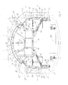
- FIG. 1 illustrated cross-section shows a two-lane road tunnel while concreting a formwork section.
- the shuttering device 11 arranged therein comprises a transporting carriage 13 and a tunnel shuttering 15.
- the tunnel shuttering 15 is divided into different areas, which are movable differently.
- the trolley 13 spans a construction site passage profile.
- About the trolley ceiling slab 17 is arranged.
- the slab formwork 17 can be lowered together with the trolley.
- the side wall formwork 19, 19 ' also includes a foot end 23, 23', which is pivotable about a second pivot axis 25, 25 'relative to the remaining part of the side wall formwork 19, 19'.
- an individual formwork 18, 18 ' which is project-specific. It comprises the pivot axes 21,21 'and the cam form 27,27'.
- the cam formwork comprises a cam flap 41, 41 ', which can be pivoted toward the transport carriage 13 about the pivot axis 21, 21'. Only in this position, which is pivoted toward the transport carriage, can the transport carriage be lowered.
- the slab formwork 17 is formed from three standard positions and two supplementary layers. Each standard position is formed of standard formwork elements 31, which have a formwork width of 250 cm and a radius of 510 cm.
- the supplementary layers connect outside to the standard conditions. They consist of a supplementary element 32,32 ', which is designed project-specific. Here it serves as a connection to the cam flap 41,41 'of the cam form 27,27'.
- the sidewall formwork comprises four layers. At the top is a supplementary layer of a supplementary element 42,42 'is formed.
- the supplementary element 42,42 ' forms the kink between side wall curve and cam and defines the pivot axis 21,21' for the side wall formwork 19,19 '.
- the subsequent upper layer is a standard position and includes a standard formwork element 33 of width 175 cm with the radius 510 cm.
- the adjoining the standard position lower layer comprises a flat formwork element 35 of width 175 cm with a pivot axis 25,25 'for articulating the noirabBankes 23,23'.
- the foldable foot end 23, 23 ' is articulated to the pivot axis 25, 25'.
- the tunnel formwork 15 is a one-sided formwork.
- the pressure of the concrete can therefore not be absorbed by binding together two walls forming a wall on both sides. Rather, the pressure is transmitted from one side wall formwork 19 'to the other side wall formwork 19.
- the pressure of the slab formwork 17 is supported by the side wall formwork 19, 19 'on the tunnel floor 39, in particular the banquet.
- the resulting forces are on supports 45,45 ', which are partially adjustable in length 45', passed to a cross member 43.
- the cross member 43 is part of the trolley 13th
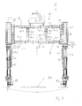
- FIG. 2 the tunnel formwork is shown in a traversing position.
- the side wall formwork 19,19 'are pivoted to the trolley 13 zoom.
- the trolley 13 is lowered.
- all formwork parts are removed from the wall of the freshly concreted tunnel tube 47, so that the formwork device 11 can be moved on the wheels of the rolling feet 49 via the tunnel bottom 39.
- the formwork can be cleaned in this position.
- At the new position in the tunnel she will return to the in FIG. 1 shown concreting position brought.
- the trolley 13 is shown without the tunnel formwork.
- the trolley 13 comprises wheels in rolling feet 49.
- the rolling feet 49 are formed transversely to the tunnel direction against the lifting legs 51 loading thereon displaceable.
- the lifting legs 51 each carry a two in the tunnel longitudinal direction truss 53.53 '.
- the lifting legs 51 are each arranged in the feed direction of the formwork device 11 in front of and behind the tunnel formwork 15 on the truss 53.53 '. Thanks to the height adjustability of the lifting legs 51, the tunnel formwork 15 can be concreted with its vertex to the vertex height of the tunnel tube 47 (FIG. Fig. 2 ) and lowered to move by about 70 cm.
- the lifting legs 51 comprise a lifting part 51.1 and a hip part 51.2.
- the lifting part 51.1 is equipped on three sides with mounting flanges 75. It can therefore be mounted on the front side (and front or rear) or on the outside of the truss girders 53,53 '.
- the hip part 51.2 is equipped on four sides with such mounting flanges 75. It can therefore be mounted on all sides.
- the trusses have corresponding mounting surfaces. These mounting surfaces and the mounting flanges 75 on the lifting legs 51 are perforated in a 12 cm grid. The perforation allows the lifting legs each to be mounted on a truss-specific height on the truss 53.
- the lifting part 51.1 can be mounted on each of the remaining sides of the hip part 51.2.
- the altitude can be selected according to the grid of perforations.
- the hip part and the lifting part are also, as shown and preferred, screwed together in the axial position.
- a pressure plate 77.1 and 77.2 formed on the hip part and the lifting part. These printing plates can be screwed together.
- the pressure plate 77.1 is formed on a pressure cover 79, to which pressure cover 79 attaches the hydraulic cylinder in the interior of the Hubbeins.
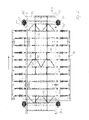
- the cross member 43 are also formed as trusses. They have a top flange 44 and a bottom flange 46, and vertical struts 48, which are bolted together angle stiff.
- the length and the height of the cross member 43 are to be dimensioned project specific.
- the cross member is composed of a modular system. This modular system includes cross member bars 40.1, 40.2, 40.3, 40.4 different length.
- the lengths of the cross member bars 40 are formed in a 10 cm grid.
- Each crossbar 40 has the same end plates 71 and the same cross section of the steel profile.
- the steel profile is a practically square H-profile.
- each cross member bar 40 can be arranged both on the end side for extension of another cross member rod 40, and also on a flange 73 of another cross member rod 40 to form a vertical strut 48. Further, it is possible to insert diagonal bars in the cross member 43. These are formed in the nature of the tunnel formwork 15 supporting columns 45.
- a complementary cross member bar can be made to achieve a cross member length, which is outside the grid.
- the selected 10 cm grid should be sufficiently small, since the rolling feet 49 are each designed to be displaceable by up to 10 cm, so that it is easy to park on a rail not arranged in a 10 cm grid.
- the cross members 43 are formed in the present example with two horizontal bands arranged one above the other, namely a top flange 44 and a bottom flange 46, which extend from truss girder 53 to truss girder 53 'and are screwed thereto.
- These horizontal collars 44,46 are each composed of three cross member rods, namely two 200 cm rods 40.1, which are screwed to the truss girders 53,53 ', and between a 100 cm rod 40.3, with its end plates 71 to the end plates 71 of the 200 cm rods 40.1 is screwed.
- the lower flange 46 and the upper flange 44 are connected to vertical struts 48.
- the vertical struts 48 which are each also a 120 cm rod 40.2 and a 50 cm rod 40.4 are formed.
- the end plates 71 of the vertical struts 48 are on the flanges of the H-profiles of the horizontal collars Screwed 44.46.
- the selected height of the cross members 43 with 170 cm long vertical webs 48 is the maximum height in the present truss girders 53.
- the 50 cm rod 40.4 can be replaced by a 20 cm rod (not shown), for example. It is also possible to replace the 120 cm rod 40.2 with a 100 cm rod 40.3.
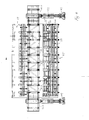
- the truss 53 is visible in its longitudinal extent.
- the truss 53 is composed of 4 pieces.
- the basic element 50.1 has a length of 10 meters and is a welded construction.
- An additional truss 50.2 complements the length of the base element 50.1 on the project-specific desired length of the longitudinal truss.
- the supplementary truss girders 50.2 generally have a dimension that is tailored to the truss grid size. In the present example, the framework is placed on a grid of 125 cm and the supplementary truss 50.2 has a length of 250 cm.
- an end piece 50.3, 50.4 is arranged at both ends of the truss girder 53. This end piece is screwed to the base element 50.1 or to the supplementary truss 50.2.
- Each end piece 50.3, 50.4 is equipped with mounting surfaces for mounting the lifting legs 51. In the area of these mounting surfaces, perforated flanges are formed on the opposite side of the end piece 50.3, 50.4, on which cross members 43 can be mounted.
- Such flanges for mounting the cross member are also formed on each vertical strut of the truss girder 53.
- the ends of the base element 50.1, the supplementary truss girder 50.2, and the end pieces 50.3 and 50.4 in total are stiffened with sheets and stiffening ribs. Between the vertical bars of the truss girder 53 diagonal bars for stiffening the truss girder 53 are present.
- struts 55 are hooked into the holes of the cross member bars 40 and the required length up or twisted together.
- These struts 55 are formed as clamping elements and have a central part with two opposing internal threads and two end portions, each with the corresponding external threads. These struts can therefore be used diagonally or orthogonally and serve only as a composite of the support system.
Landscapes
- Engineering & Computer Science (AREA)
- Architecture (AREA)
- Structural Engineering (AREA)
- Mining & Mineral Resources (AREA)
- Civil Engineering (AREA)
- Life Sciences & Earth Sciences (AREA)
- General Life Sciences & Earth Sciences (AREA)
- Geochemistry & Mineralogy (AREA)
- Geology (AREA)
- Bridges Or Land Bridges (AREA)
- Conveying And Assembling Of Building Elements In Situ (AREA)
- Lining And Supports For Tunnels (AREA)
Applications Claiming Priority (1)
| Application Number | Priority Date | Filing Date | Title |
|---|---|---|---|
| CH00205/08A CH702241B1 (de) | 2008-02-13 | 2008-02-13 | Transportwagen. |
Publications (2)
| Publication Number | Publication Date |
|---|---|
| EP2090744A1 true EP2090744A1 (fr) | 2009-08-19 |
| EP2090744B1 EP2090744B1 (fr) | 2011-05-11 |
Family
ID=39739642
Family Applications (1)
| Application Number | Title | Priority Date | Filing Date |
|---|---|---|---|
| EP09152832A Active EP2090744B1 (fr) | 2008-02-13 | 2009-02-13 | Chariot de transport |
Country Status (3)
| Country | Link |
|---|---|
| EP (1) | EP2090744B1 (fr) |
| AT (1) | ATE509185T1 (fr) |
| CH (1) | CH702241B1 (fr) |
Cited By (17)
| Publication number | Priority date | Publication date | Assignee | Title |
|---|---|---|---|---|
| CN101967986A (zh) * | 2010-09-10 | 2011-02-09 | 四川省锐隆路桥机械设备有限公司 | 围护桩段钢支撑跨步式拱顶内模衬砌台车 |
| CN102536261A (zh) * | 2012-01-14 | 2012-07-04 | 湖南五新重型装备有限公司 | 一种伸缩式紧急避车带隧道衬砌台车 |
| CN102536267A (zh) * | 2012-03-07 | 2012-07-04 | 中国水利水电第五工程局有限公司 | 用全断面针梁台车进行大坡度斜井施工的方法及针梁台车 |
| CN102619534A (zh) * | 2012-04-12 | 2012-08-01 | 中国水利水电第十四工程局有限公司 | 一种轻型移动式钢模台车 |
| CN102777192A (zh) * | 2012-08-15 | 2012-11-14 | 中国水利水电第十四工程局有限公司 | 一种简易钢模台车 |
| CN102852529A (zh) * | 2012-09-29 | 2013-01-02 | 中铁八局集团第一工程有限公司 | 用于隧道二次衬砌台车端头模板加固的方法 |
| CN103195439A (zh) * | 2013-04-10 | 2013-07-10 | 中国长江三峡集团公司 | 用于隧洞施工的多功能作业台车 |
| CN103615261A (zh) * | 2013-11-25 | 2014-03-05 | 国电大渡河沙坪水电建设有限公司 | 一种高度可调式钢模台车及其实现方法 |
| CN104806269A (zh) * | 2015-04-08 | 2015-07-29 | 湖南五新重型装备有限公司 | 一种隧道衬砌台车的全自动液压走行系统 |
| CN105927247A (zh) * | 2016-04-15 | 2016-09-07 | 鞍山市立业机械制造有限公司 | 大断面全自动机械数控台车及其施工方法 |
| CN106640138A (zh) * | 2016-12-29 | 2017-05-10 | 中国人民解放军63926部队 | 廊道分离式钢模板台车 |
| CN106640131A (zh) * | 2016-11-24 | 2017-05-10 | 中国人民解放军63926部队 | 一种模块化的变截面隧道衬砌台车 |
| CN108457677A (zh) * | 2018-05-29 | 2018-08-28 | 湖南五新模板有限公司 | 一种整体式水沟电缆槽模板自动作业车 |
| CN108625883A (zh) * | 2018-07-10 | 2018-10-09 | 中铁隧道集团二处有限公司 | 一种用于隧道二次砌衬施工的锚段台车及施工方法 |
| CN108868824A (zh) * | 2018-06-29 | 2018-11-23 | 涪特智能装备(重庆)有限公司 | 一种隧道二衬环向钢筋铺设台车及铺设方法 |
| CN109763839A (zh) * | 2018-12-27 | 2019-05-17 | 中铁广州工程局集团有限公司 | 一种全断面自行式液压台车模板施工方法 |
| CN111734431A (zh) * | 2020-06-24 | 2020-10-02 | 高军 | 一种软岩隧道全断面微台阶开挖施工用台车 |
Families Citing this family (1)
| Publication number | Priority date | Publication date | Assignee | Title |
|---|---|---|---|---|
| CN111663430B (zh) * | 2020-06-09 | 2022-02-22 | 中铁十一局集团汉江重工有限公司 | 一种角度可调且横向可调的移动栈桥 |
Citations (3)
| Publication number | Priority date | Publication date | Assignee | Title |
|---|---|---|---|---|
| US5114295A (en) * | 1989-03-13 | 1992-05-19 | Sea Flats Aktiebolag | Container handling wagon |
| EP1136650A1 (fr) | 2000-03-24 | 2001-09-26 | MECSIDER S.p.A. | Chariot ajustable en taille pour coffrage de tunnel |
| DE102005028767A1 (de) * | 2005-06-08 | 2006-12-28 | Domesle Schalungs- Und Metallbau Gmbh | Schalungswagen sowie Schalung mit einem solchen Schalungswagen |
Family Cites Families (4)
| Publication number | Priority date | Publication date | Assignee | Title |
|---|---|---|---|---|
| US4378072A (en) * | 1980-06-16 | 1983-03-29 | Rpc Corporation | Gantry crane |
| FR2691204A1 (fr) * | 1992-05-13 | 1993-11-19 | Al Cant Coffrages | Dispositif de coffrage pour la réalisation d'une paroi en béton notamment d'un tunnel. |
| US5575607A (en) * | 1994-11-02 | 1996-11-19 | United Technologies Corporation | Jet engine transport vehicle lift system and a build cell |
| FR2752013B1 (fr) * | 1996-07-30 | 1998-10-23 | Parra Robert | Anneau de coffrage courbe |
-
2008
- 2008-02-13 CH CH00205/08A patent/CH702241B1/de not_active IP Right Cessation
-
2009
- 2009-02-13 EP EP09152832A patent/EP2090744B1/fr active Active
- 2009-02-13 AT AT09152832T patent/ATE509185T1/de active
Patent Citations (3)
| Publication number | Priority date | Publication date | Assignee | Title |
|---|---|---|---|---|
| US5114295A (en) * | 1989-03-13 | 1992-05-19 | Sea Flats Aktiebolag | Container handling wagon |
| EP1136650A1 (fr) | 2000-03-24 | 2001-09-26 | MECSIDER S.p.A. | Chariot ajustable en taille pour coffrage de tunnel |
| DE102005028767A1 (de) * | 2005-06-08 | 2006-12-28 | Domesle Schalungs- Und Metallbau Gmbh | Schalungswagen sowie Schalung mit einem solchen Schalungswagen |
Cited By (27)
| Publication number | Priority date | Publication date | Assignee | Title |
|---|---|---|---|---|
| CN101967986B (zh) * | 2010-09-10 | 2012-07-25 | 成都锐龙机械制造有限公司 | 围护桩段钢支撑跨步式拱顶内模衬砌台车 |
| CN101967986A (zh) * | 2010-09-10 | 2011-02-09 | 四川省锐隆路桥机械设备有限公司 | 围护桩段钢支撑跨步式拱顶内模衬砌台车 |
| CN102536261A (zh) * | 2012-01-14 | 2012-07-04 | 湖南五新重型装备有限公司 | 一种伸缩式紧急避车带隧道衬砌台车 |
| CN102536261B (zh) * | 2012-01-14 | 2014-06-18 | 湖南五新重型装备有限公司 | 一种伸缩式紧急避车带隧道衬砌台车 |
| CN102536267A (zh) * | 2012-03-07 | 2012-07-04 | 中国水利水电第五工程局有限公司 | 用全断面针梁台车进行大坡度斜井施工的方法及针梁台车 |
| CN102619534A (zh) * | 2012-04-12 | 2012-08-01 | 中国水利水电第十四工程局有限公司 | 一种轻型移动式钢模台车 |
| CN102777192A (zh) * | 2012-08-15 | 2012-11-14 | 中国水利水电第十四工程局有限公司 | 一种简易钢模台车 |
| CN102852529A (zh) * | 2012-09-29 | 2013-01-02 | 中铁八局集团第一工程有限公司 | 用于隧道二次衬砌台车端头模板加固的方法 |
| CN103195439B (zh) * | 2013-04-10 | 2016-01-20 | 中国长江三峡集团公司 | 用于隧洞施工的多功能作业台车 |
| CN103195439A (zh) * | 2013-04-10 | 2013-07-10 | 中国长江三峡集团公司 | 用于隧洞施工的多功能作业台车 |
| CN103615261B (zh) * | 2013-11-25 | 2016-06-22 | 国电大渡河沙坪水电建设有限公司 | 一种高度可调式钢模台车及其实现方法 |
| CN103615261A (zh) * | 2013-11-25 | 2014-03-05 | 国电大渡河沙坪水电建设有限公司 | 一种高度可调式钢模台车及其实现方法 |
| CN104806269B (zh) * | 2015-04-08 | 2017-04-26 | 湖南五新隧道智能装备股份有限公司 | 一种隧道衬砌台车的全自动液压走行系统 |
| CN104806269A (zh) * | 2015-04-08 | 2015-07-29 | 湖南五新重型装备有限公司 | 一种隧道衬砌台车的全自动液压走行系统 |
| CN105927247A (zh) * | 2016-04-15 | 2016-09-07 | 鞍山市立业机械制造有限公司 | 大断面全自动机械数控台车及其施工方法 |
| CN106640131B (zh) * | 2016-11-24 | 2019-01-18 | 中国人民解放军63926部队 | 一种模块化的变截面隧道衬砌台车 |
| CN106640131A (zh) * | 2016-11-24 | 2017-05-10 | 中国人民解放军63926部队 | 一种模块化的变截面隧道衬砌台车 |
| CN106640138A (zh) * | 2016-12-29 | 2017-05-10 | 中国人民解放军63926部队 | 廊道分离式钢模板台车 |
| CN108457677A (zh) * | 2018-05-29 | 2018-08-28 | 湖南五新模板有限公司 | 一种整体式水沟电缆槽模板自动作业车 |
| CN108457677B (zh) * | 2018-05-29 | 2024-02-13 | 湖南五新模板有限公司 | 一种整体式水沟电缆槽模板自动作业车 |
| CN108868824A (zh) * | 2018-06-29 | 2018-11-23 | 涪特智能装备(重庆)有限公司 | 一种隧道二衬环向钢筋铺设台车及铺设方法 |
| CN108868824B (zh) * | 2018-06-29 | 2023-08-22 | 涪特智能装备(重庆)有限公司 | 一种隧道二衬环向钢筋铺设台车及铺设方法 |
| CN108625883B (zh) * | 2018-07-10 | 2023-12-15 | 中铁隧道集团二处有限公司 | 一种用于隧道二次砌衬施工的锚段台车及施工方法 |
| CN108625883A (zh) * | 2018-07-10 | 2018-10-09 | 中铁隧道集团二处有限公司 | 一种用于隧道二次砌衬施工的锚段台车及施工方法 |
| CN109763839A (zh) * | 2018-12-27 | 2019-05-17 | 中铁广州工程局集团有限公司 | 一种全断面自行式液压台车模板施工方法 |
| CN111734431A (zh) * | 2020-06-24 | 2020-10-02 | 高军 | 一种软岩隧道全断面微台阶开挖施工用台车 |
| CN111734431B (zh) * | 2020-06-24 | 2022-04-08 | 高军 | 一种软岩隧道全断面微台阶开挖施工用台车 |
Also Published As
| Publication number | Publication date |
|---|---|
| ATE509185T1 (de) | 2011-05-15 |
| CH702241B1 (de) | 2011-05-31 |
| EP2090744B1 (fr) | 2011-05-11 |
Similar Documents
| Publication | Publication Date | Title |
|---|---|---|
| EP2090744B1 (fr) | Chariot de transport | |
| EP1935833B1 (fr) | Elément de grille pour une grande grue mobile et son procédé de montage | |
| EP0133850A1 (fr) | Procédé et appareil pour la construction d'un tablier de pont en béton précontraint | |
| DE1903129B2 (de) | Vorrichtung zum Anschließen eines Trägers an eine Betonstütze | |
| EP2882634B1 (fr) | Structure de convoyeur aerien au-dessus d'un portique | |
| EP3016843B1 (fr) | Convoyeur aérien équipé de modules de châssis porteur | |
| CH702134B1 (de) | Schalungsvorrichtung. | |
| EP1905900A2 (fr) | Pont doté de deux plaques en treillis et son procédé de fabrication | |
| DE102007047919B4 (de) | Traggerüst und Verfahren zur Demontage und Transport | |
| EP0004251A1 (fr) | Procédé d'édification d'un ouvrage portant, dispositif pour mettre en oeuvre ce procédé et jeu d'éléments pour construire le dispositif | |
| DE202008012407U1 (de) | Freitragende Stahlhalle | |
| DE1659218C3 (de) | Verbundfachwerkträger sowie Verfahren zu dessen Montage | |
| EP0134823A1 (fr) | Appareil pour la construction tranche par tranche d'un tablier de pont en béton précontraint | |
| DE19607952C2 (de) | Traggerüst zur Stützung von Massivbauwerken | |
| DE2423953C2 (de) | Verfahrbares Schalungsgerät zum Betonieren von Tunnelröhren | |
| EP3725975B1 (fr) | Procédé de fabrication d'un module de parc de stationnement | |
| WO2017127947A1 (fr) | Structure porteuse pour système de construction de halls, de scènes, de tribunes ou de passerelles, pouvant être montée et démontée plusieurs fois | |
| DE1295580C2 (de) | Geruest zum abschnittsweisen herstellen des ueberbaus von bruecken, hochstrassen o.dgl. aus stahlbeton oder spannbeton | |
| DE1905437A1 (de) | Konstruktionsteil | |
| EP0133849B1 (fr) | Système de fixation d'une matrice d'impression par stencil sur un tambour d'impression | |
| DE202004011443U1 (de) | Abstützvorrichtung für Traggestelle mit vorkragenden Lasten | |
| EP1762657A2 (fr) | Système de pont modulaire pour utilisations militaires | |
| DE102004035416B4 (de) | Abstützvorrichtung für Traggestelle mit vorkragenden Lasten | |
| DE20021451U1 (de) | Einseitig montierbare mobile Brücke in Leichtbauweise für das Überqueren von Hindernissen mit Fahrzeugen | |
| AT404041B (de) | Stahlbeton-bogenbrücke |
Legal Events
| Date | Code | Title | Description |
|---|---|---|---|
| PUAI | Public reference made under article 153(3) epc to a published international application that has entered the european phase |
Free format text: ORIGINAL CODE: 0009012 |
|
| AK | Designated contracting states |
Kind code of ref document: A1 Designated state(s): AT BE BG CH CY CZ DE DK EE ES FI FR GB GR HR HU IE IS IT LI LT LU LV MC MK MT NL NO PL PT RO SE SI SK TR |
|
| AX | Request for extension of the european patent |
Extension state: AL BA RS |
|
| 17P | Request for examination filed |
Effective date: 20100116 |
|
| 17Q | First examination report despatched |
Effective date: 20100212 |
|
| AKX | Designation fees paid |
Designated state(s): AT BE BG CH CY CZ DE DK EE ES FI FR GB GR HR HU IE IS IT LI LT LU LV MC MK MT NL NO PL PT RO SE SI SK TR |
|
| GRAP | Despatch of communication of intention to grant a patent |
Free format text: ORIGINAL CODE: EPIDOSNIGR1 |
|
| GRAS | Grant fee paid |
Free format text: ORIGINAL CODE: EPIDOSNIGR3 |
|
| GRAA | (expected) grant |
Free format text: ORIGINAL CODE: 0009210 |
|
| AK | Designated contracting states |
Kind code of ref document: B1 Designated state(s): AT BE BG CH CY CZ DE DK EE ES FI FR GB GR HR HU IE IS IT LI LT LU LV MC MK MT NL NO PL PT RO SE SI SK TR |
|
| REG | Reference to a national code |
Ref country code: GB Ref legal event code: FG4D Free format text: NOT ENGLISH |
|
| REG | Reference to a national code |
Ref country code: CH Ref legal event code: EP |
|
| REG | Reference to a national code |
Ref country code: IE Ref legal event code: FG4D |
|
| REG | Reference to a national code |
Ref country code: CH Ref legal event code: NV Representative=s name: RIEDERER HASLER & PARTNER PATENTANWAELTE AG |
|
| REG | Reference to a national code |
Ref country code: DE Ref legal event code: R096 Ref document number: 502009000640 Country of ref document: DE Effective date: 20110622 |
|
| REG | Reference to a national code |
Ref country code: NL Ref legal event code: VDEP Effective date: 20110511 |
|
| PG25 | Lapsed in a contracting state [announced via postgrant information from national office to epo] |
Ref country code: NO Free format text: LAPSE BECAUSE OF FAILURE TO SUBMIT A TRANSLATION OF THE DESCRIPTION OR TO PAY THE FEE WITHIN THE PRESCRIBED TIME-LIMIT Effective date: 20110811 Ref country code: LT Free format text: LAPSE BECAUSE OF FAILURE TO SUBMIT A TRANSLATION OF THE DESCRIPTION OR TO PAY THE FEE WITHIN THE PRESCRIBED TIME-LIMIT Effective date: 20110511 Ref country code: SE Free format text: LAPSE BECAUSE OF FAILURE TO SUBMIT A TRANSLATION OF THE DESCRIPTION OR TO PAY THE FEE WITHIN THE PRESCRIBED TIME-LIMIT Effective date: 20110511 Ref country code: PT Free format text: LAPSE BECAUSE OF FAILURE TO SUBMIT A TRANSLATION OF THE DESCRIPTION OR TO PAY THE FEE WITHIN THE PRESCRIBED TIME-LIMIT Effective date: 20110912 |
|
| PG25 | Lapsed in a contracting state [announced via postgrant information from national office to epo] |
Ref country code: GR Free format text: LAPSE BECAUSE OF FAILURE TO SUBMIT A TRANSLATION OF THE DESCRIPTION OR TO PAY THE FEE WITHIN THE PRESCRIBED TIME-LIMIT Effective date: 20110812 Ref country code: ES Free format text: LAPSE BECAUSE OF FAILURE TO SUBMIT A TRANSLATION OF THE DESCRIPTION OR TO PAY THE FEE WITHIN THE PRESCRIBED TIME-LIMIT Effective date: 20110822 Ref country code: CY Free format text: LAPSE BECAUSE OF FAILURE TO SUBMIT A TRANSLATION OF THE DESCRIPTION OR TO PAY THE FEE WITHIN THE PRESCRIBED TIME-LIMIT Effective date: 20110511 Ref country code: SI Free format text: LAPSE BECAUSE OF FAILURE TO SUBMIT A TRANSLATION OF THE DESCRIPTION OR TO PAY THE FEE WITHIN THE PRESCRIBED TIME-LIMIT Effective date: 20110511 Ref country code: IS Free format text: LAPSE BECAUSE OF FAILURE TO SUBMIT A TRANSLATION OF THE DESCRIPTION OR TO PAY THE FEE WITHIN THE PRESCRIBED TIME-LIMIT Effective date: 20110911 Ref country code: FI Free format text: LAPSE BECAUSE OF FAILURE TO SUBMIT A TRANSLATION OF THE DESCRIPTION OR TO PAY THE FEE WITHIN THE PRESCRIBED TIME-LIMIT Effective date: 20110511 Ref country code: LV Free format text: LAPSE BECAUSE OF FAILURE TO SUBMIT A TRANSLATION OF THE DESCRIPTION OR TO PAY THE FEE WITHIN THE PRESCRIBED TIME-LIMIT Effective date: 20110511 |
|
| REG | Reference to a national code |
Ref country code: IE Ref legal event code: FD4D |
|
| PG25 | Lapsed in a contracting state [announced via postgrant information from national office to epo] |
Ref country code: NL Free format text: LAPSE BECAUSE OF FAILURE TO SUBMIT A TRANSLATION OF THE DESCRIPTION OR TO PAY THE FEE WITHIN THE PRESCRIBED TIME-LIMIT Effective date: 20110511 |
|
| PG25 | Lapsed in a contracting state [announced via postgrant information from national office to epo] |
Ref country code: IE Free format text: LAPSE BECAUSE OF FAILURE TO SUBMIT A TRANSLATION OF THE DESCRIPTION OR TO PAY THE FEE WITHIN THE PRESCRIBED TIME-LIMIT Effective date: 20110511 Ref country code: EE Free format text: LAPSE BECAUSE OF FAILURE TO SUBMIT A TRANSLATION OF THE DESCRIPTION OR TO PAY THE FEE WITHIN THE PRESCRIBED TIME-LIMIT Effective date: 20110511 Ref country code: CZ Free format text: LAPSE BECAUSE OF FAILURE TO SUBMIT A TRANSLATION OF THE DESCRIPTION OR TO PAY THE FEE WITHIN THE PRESCRIBED TIME-LIMIT Effective date: 20110511 |
|
| PG25 | Lapsed in a contracting state [announced via postgrant information from national office to epo] |
Ref country code: PL Free format text: LAPSE BECAUSE OF FAILURE TO SUBMIT A TRANSLATION OF THE DESCRIPTION OR TO PAY THE FEE WITHIN THE PRESCRIBED TIME-LIMIT Effective date: 20110511 Ref country code: SK Free format text: LAPSE BECAUSE OF FAILURE TO SUBMIT A TRANSLATION OF THE DESCRIPTION OR TO PAY THE FEE WITHIN THE PRESCRIBED TIME-LIMIT Effective date: 20110511 |
|
| PLBE | No opposition filed within time limit |
Free format text: ORIGINAL CODE: 0009261 |
|
| STAA | Information on the status of an ep patent application or granted ep patent |
Free format text: STATUS: NO OPPOSITION FILED WITHIN TIME LIMIT |
|
| 26N | No opposition filed |
Effective date: 20120214 |
|
| PG25 | Lapsed in a contracting state [announced via postgrant information from national office to epo] |
Ref country code: IT Free format text: LAPSE BECAUSE OF FAILURE TO SUBMIT A TRANSLATION OF THE DESCRIPTION OR TO PAY THE FEE WITHIN THE PRESCRIBED TIME-LIMIT Effective date: 20110511 Ref country code: HR Free format text: LAPSE BECAUSE OF FAILURE TO SUBMIT A TRANSLATION OF THE DESCRIPTION OR TO PAY THE FEE WITHIN THE PRESCRIBED TIME-LIMIT Effective date: 20111123 |
|
| REG | Reference to a national code |
Ref country code: DE Ref legal event code: R097 Ref document number: 502009000640 Country of ref document: DE Effective date: 20120214 |
|
| BERE | Be: lapsed |
Owner name: JORIMANN STAHL A.G. Effective date: 20120228 |
|
| PG25 | Lapsed in a contracting state [announced via postgrant information from national office to epo] |
Ref country code: MC Free format text: LAPSE BECAUSE OF NON-PAYMENT OF DUE FEES Effective date: 20120229 |
|
| REG | Reference to a national code |
Ref country code: FR Ref legal event code: ST Effective date: 20121031 |
|
| PG25 | Lapsed in a contracting state [announced via postgrant information from national office to epo] |
Ref country code: BE Free format text: LAPSE BECAUSE OF NON-PAYMENT OF DUE FEES Effective date: 20120228 |
|
| PG25 | Lapsed in a contracting state [announced via postgrant information from national office to epo] |
Ref country code: FR Free format text: LAPSE BECAUSE OF NON-PAYMENT OF DUE FEES Effective date: 20120229 |
|
| PG25 | Lapsed in a contracting state [announced via postgrant information from national office to epo] |
Ref country code: MK Free format text: LAPSE BECAUSE OF FAILURE TO SUBMIT A TRANSLATION OF THE DESCRIPTION OR TO PAY THE FEE WITHIN THE PRESCRIBED TIME-LIMIT Effective date: 20110511 |
|
| PG25 | Lapsed in a contracting state [announced via postgrant information from national office to epo] |
Ref country code: BG Free format text: LAPSE BECAUSE OF FAILURE TO SUBMIT A TRANSLATION OF THE DESCRIPTION OR TO PAY THE FEE WITHIN THE PRESCRIBED TIME-LIMIT Effective date: 20110811 |
|
| PG25 | Lapsed in a contracting state [announced via postgrant information from national office to epo] |
Ref country code: MT Free format text: LAPSE BECAUSE OF FAILURE TO SUBMIT A TRANSLATION OF THE DESCRIPTION OR TO PAY THE FEE WITHIN THE PRESCRIBED TIME-LIMIT Effective date: 20110511 |
|
| GBPC | Gb: european patent ceased through non-payment of renewal fee |
Effective date: 20130213 |
|
| PG25 | Lapsed in a contracting state [announced via postgrant information from national office to epo] |
Ref country code: HR Free format text: LAPSE BECAUSE OF FAILURE TO SUBMIT A TRANSLATION OF THE DESCRIPTION OR TO PAY THE FEE WITHIN THE PRESCRIBED TIME-LIMIT Effective date: 20110511 |
|
| PG25 | Lapsed in a contracting state [announced via postgrant information from national office to epo] |
Ref country code: GB Free format text: LAPSE BECAUSE OF NON-PAYMENT OF DUE FEES Effective date: 20130213 |
|
| PG25 | Lapsed in a contracting state [announced via postgrant information from national office to epo] |
Ref country code: TR Free format text: LAPSE BECAUSE OF FAILURE TO SUBMIT A TRANSLATION OF THE DESCRIPTION OR TO PAY THE FEE WITHIN THE PRESCRIBED TIME-LIMIT Effective date: 20110511 |
|
| PG25 | Lapsed in a contracting state [announced via postgrant information from national office to epo] |
Ref country code: LU Free format text: LAPSE BECAUSE OF NON-PAYMENT OF DUE FEES Effective date: 20120213 |
|
| PG25 | Lapsed in a contracting state [announced via postgrant information from national office to epo] |
Ref country code: HU Free format text: LAPSE BECAUSE OF FAILURE TO SUBMIT A TRANSLATION OF THE DESCRIPTION OR TO PAY THE FEE WITHIN THE PRESCRIBED TIME-LIMIT Effective date: 20090213 |
|
| PGFP | Annual fee paid to national office [announced via postgrant information from national office to epo] |
Ref country code: CH Payment date: 20170228 Year of fee payment: 9 Ref country code: DE Payment date: 20170217 Year of fee payment: 9 |
|
| PGFP | Annual fee paid to national office [announced via postgrant information from national office to epo] |
Ref country code: AT Payment date: 20170217 Year of fee payment: 9 |
|
| REG | Reference to a national code |
Ref country code: DE Ref legal event code: R119 Ref document number: 502009000640 Country of ref document: DE |
|
| REG | Reference to a national code |
Ref country code: CH Ref legal event code: PL |
|
| REG | Reference to a national code |
Ref country code: AT Ref legal event code: MM01 Ref document number: 509185 Country of ref document: AT Kind code of ref document: T Effective date: 20180213 |
|
| PG25 | Lapsed in a contracting state [announced via postgrant information from national office to epo] |
Ref country code: AT Free format text: LAPSE BECAUSE OF NON-PAYMENT OF DUE FEES Effective date: 20180213 Ref country code: LI Free format text: LAPSE BECAUSE OF NON-PAYMENT OF DUE FEES Effective date: 20180228 Ref country code: CH Free format text: LAPSE BECAUSE OF NON-PAYMENT OF DUE FEES Effective date: 20180228 |
|
| PG25 | Lapsed in a contracting state [announced via postgrant information from national office to epo] |
Ref country code: DE Free format text: LAPSE BECAUSE OF NON-PAYMENT OF DUE FEES Effective date: 20180901 |