EP2090757A2 - Agencement de levier basculant doté d'un coussinet comprenant des rainures - Google Patents
Agencement de levier basculant doté d'un coussinet comprenant des rainures Download PDFInfo
- Publication number
- EP2090757A2 EP2090757A2 EP08018202A EP08018202A EP2090757A2 EP 2090757 A2 EP2090757 A2 EP 2090757A2 EP 08018202 A EP08018202 A EP 08018202A EP 08018202 A EP08018202 A EP 08018202A EP 2090757 A2 EP2090757 A2 EP 2090757A2
- Authority
- EP
- European Patent Office
- Prior art keywords
- rocker arm
- shell
- bearing
- groove
- oil
- Prior art date
- Legal status (The legal status is an assumption and is not a legal conclusion. Google has not performed a legal analysis and makes no representation as to the accuracy of the status listed.)
- Granted
Links
Images

Classifications
-
- F—MECHANICAL ENGINEERING; LIGHTING; HEATING; WEAPONS; BLASTING
- F01—MACHINES OR ENGINES IN GENERAL; ENGINE PLANTS IN GENERAL; STEAM ENGINES
- F01L—CYCLICALLY OPERATING VALVES FOR MACHINES OR ENGINES
- F01L1/00—Valve-gear or valve arrangements, e.g. lift-valve gear
- F01L1/12—Transmitting gear between valve drive and valve
- F01L1/18—Rocking arms or levers
- F01L1/181—Centre pivot rocking arms
Definitions
- the invention relates to a rocker arm assembly of an internal combustion engine with a rocker arm and a journal, wherein the bearing pin has a trained as a running surface outer peripheral surface and engages in a lined with a bearing shell central bore of the rocker arm, so that the rocker arm is pivotally mounted on the running surface of the journal, the Bearing journal has a running in its inner first oil passage, which opens in at least one arranged below a central longitudinal axis of the journal outlet opening on the tread, and the fixedly connected to the rocker bearing shell has a hollow cylindrical shape with a shell outer surface and a shell inner surface.
- Kipphebelan extract has the bearing shell, which is also referred to as a bearing bush, on its shell inner surface, ie its inside or its inner, ie the interior of the hollow cylinder facing peripheral surface, inner grooves which are in communication with the first oil passage of the journal.
- a bearing bush On its shell inner surface, ie its inside or its inner, ie the interior of the hollow cylinder facing peripheral surface, inner grooves which are in communication with the first oil passage of the journal.
- the object of the invention is therefore to provide a rocker arm assembly of the type described, in which a small oil loss occurs.
- a rocker arm assembly according to the features of claim 1 is given.
- a lower half of the shell inner surface is provided with at least one inner groove extending in the circumferential direction and ending on both sides below the central longitudinal axis, which extends at least into a region in which the outlet opening of the first oil channel is arranged at a basic position of the rocker arm.
- the outer shell surface is provided with at least one extending in the circumferential direction, extending to an inlet opening of a rocker arm extending in the second oil groove extending outer groove.
- the bearing shell has at least one through groove connecting the inner groove and the outer groove.
- the grooves in the bearing shell extend only partially on the inside thereof. These inner grooves each terminate below the central longitudinal axis, ie below a horizontal plane extending through the central longitudinal axis. They are primarily used to lubricate the tread.
- outer grooves are provided which are in communication with the / the réellenut / s and which are intended to supply oil to the second oil channels connected to the secondary consumers. This division is favorable.
- the inner and outer grooves can be designed specifically according to their respective function.
- this measure also has an advantageous effect on the otherwise occurring under load oil loss. Since the internal grooves already end below the central longitudinal axis, the internal grooves are even additionally sealed under load by the bearing journal, which is then pressed more strongly against the lower half of the bearing shell. The larger gap forming under the action of load in the region of the upper half of the bearing shell between the same and the bearing pin does not result in any appreciably increased oil loss in the rocker arm arrangement according to the invention. This area is not supplied with oil in contrast to the prior art. The inner grooves end before, so still in the lower half.
- the outer grooves which may in particular extend into this region of the upper half of the central bore of the rocker arm, to feed the well disposed there inlet openings of the second oil channels with oil, are due to the in this area in particular unbroken wall of the bearing shell of the under load enlarged gap separated.
- the same advantageous oil-saving behavior results when the bearing clearance during runtime, e.g. due to aging, enlarged.
- the first oil passage has a bearing pin completely penetrating and extending below the central longitudinal axis transverse bore. This results in two outlets communicating with the inner groove (s) on the tread, thus providing an improved oil supply to the inner groove (s).
- the inlet opening is located above the central longitudinal axis in an inner wall of the central bore of the rocker arm, and the outer groove begins below the central longitudinal axis and ends above the central longitudinal axis, wherein it extends at least up to the inlet opening.
- the outer groove begins below the central longitudinal axis and ends above the central longitudinal axis, wherein it extends at least up to the inlet opening.
- At least two second oil passages are preferably arranged in the rocker arm and the shell outer surface is provided with at least two outer grooves, each outer groove being associated with only one of the inlet openings of the second oil passages.
- the oil supply can be adjusted specifically to the respective oil demand of the secondary consumers connected to the second oil channels.
- the outer grooves have at least partially different groove geometries, in particular different groove depths and / or different groove widths. Even so, the oil throughput in each outer groove can be set according to the specific needs.
- the through opening in the bearing shell is arranged in the region in which the outlet opening of the first oil channel is located at a basic position of the rocker arm. This results in the best or at least a very good supply of oil to the secondary consumers.
- the oil can then pass directly from the first oil channel into the outer groove (s), i. in particular without major detour within the inner groove / s.
- the inner groove and the outer groove are each formed as embossing groove.
- embossed on both sides can be produced well and inexpensively.
- no additional expenditure is incurred by the additional outer grooves, that is to say by the embossing provided on both sides.
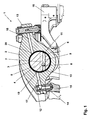
- Fig. 1 and 2 is an embodiment of a rocker arm assembly 1 shown in detail not shown with internal combustion engine. It comprises a rocker arm 2 with a central bore 3 and a bearing journal 4, whose outer peripheral surface is a bearing or running surface 5, on which the rocker arm 2 is mounted navschwenkbar means of a bearing shell 6.
- the bearing shell 6 is pressed into the central bore 3 of the rocker arm 2, so that a solid mechanical connection between these two components results.
- the bearing pin 4 engages with its running surface 5 in the bearing shell 6, wherein the bearing shell 6 is pivotally mounted about a central longitudinal axis 7 of the bearing journal 4 on the bearing journal 4.
- journal 4 Within the journal 4 extends in the axial direction, ie in the direction of the central longitudinal axis 7, eccentrically and in the lower half of the journal 4, an oil longitudinal channel 8, branches off from the height of the rocker arm 2, a transverse oil channel 9 in the direction of the tread 5.
- the oil transverse channel 9 is designed as a transverse bore, which completely penetrates the bearing journal 4 and opens on the running surface 5 into two outlet openings 10 and 11.
- the oil transverse channel 9 runs like the oil longitudinal channel 8 below the central longitudinal axis 7, or below a central longitudinal axis. 7 comprehensive horizontal plane.
- the two outlet openings 10 and 11 are located in the lower half of the journal. 4
- the rocker arm 2 has two lever arms 12 and 13, one of which is mechanically connected by means of a pressed-in this lever arm 12 ball pressure piece 14 and a push rod 15 with a camshaft not shown in detail, whereas the other lever arm 13 is in mechanical contact with a valve bridge 16.
- a valve bridge 16 By means of the valve bridge 16, two cylinder valves, also not shown in detail, of the internal combustion engine can be actuated.
- each of the lever arms 12 and 13 each have an oil passage 17 and 18, which supplies the valve bridge 16 and the possibly hydraulically operated components connected thereto or the ball pressure piece 14 as oil secondary consumers with oil.
- the oil passages 17 and 18 each have one in the upper half of the central bore 3 of the rocker arm 2, ie above the central longitudinal axis 7, arranged in an inner wall of the central bore 3 inlet opening 19 and 20th
- the bearing shell 6 fixedly connected to the rocker arm 2 is designed as a hollow cylinder having on the outer side a shell outer surface 21 which forms the outer peripheral surface of the hollow cylinder and on the inside of a shell inner surface 22, which is the inner, i. the inner space of the hollow cylinder facing peripheral surface forms, has.
- the shell outer surface 21 of the bearing shell 6 is due to the press connection directly and closely against the inner wall of the central bore 3 of the rocker arm 2.
- the shell inner surface 22 is provided in its lower half with an inner groove 23 ending on both sides below the central longitudinal axis 7, ie, in turn, below the horizontal plane passing through the central longitudinal axis 7. It runs in the circumferential direction and extends at the in Fig. 1 and 2 shown basic position of the rocker arm 2 at both ends to slightly beyond the respective outlet opening 10 and 11 of the oil transverse channel 9 addition.
- the oil cross channel 9 is connected by means of its two outlet openings 10 and 11 with this inner groove 23 in connection and feeds the latter at least in the basic position of the rocker arm 2 on both sides with oil.
- both outlet openings 10 and 11 adjoin the inner groove 23 at.
- the shell outer surface 21 is provided with two outer grooves 24 and 25, which also extend in the circumferential direction. They each begin in the lower half of the central bore 3 and extend in the upper half of the central bore 3 to slightly above each one of the inlet openings 19 and 20 also.
- Each of the oil channels 17 and 18 is connected by means of its inlet opening 19 or 20 with one of the outer grooves 24 and 25 in connection.
- Each of the outer grooves 24 and 25 feeds its associated oil passage 17 and 18 with oil.
- the inner groove 23 is connected to each of the two outer grooves 24 and 25.
- a passage opening 26 or 27 designed as a through-bore is provided in each case in the bearing shell 6.
- Each of the passage openings 26 and 27 is located opposite one of the two outlet openings 10 and 11 of the oil transverse channel 9 when the rocker arm 2 is in the home position.
- the oil supplied via the oil cross channel 9 is required firstly for lubricating the running surface 5 and secondly for supplying the auxiliary consumers connected to the oil passages 17 and 18.
- substantially separate structural means are provided in the rocker arm assembly 1.
- a corresponding partial flow of oil, which leads directly from the outlet openings 10 and 11 in the inner groove 23 is denoted by 28.
- the outer grooves 24 and 25 are provided for oil supply to the secondary consumers.
- a belonging thereto partial oil flow, from the outlet opening 10 and 11, via the passage opening 26 and 27, the outer groove 24 and 25, the inlet opening 19 and 20 in the oil passage 17 and 18 leads, is denoted by 29 and 30, respectively.
- the oil flow rate for the oil supply of the secondary consumers can be adjusted in each of the outer grooves 24 and 25 specifically to the respective requirements of each connected auxiliary consumers on the individually specified groove geometry, eg the respective groove depth or groove width. Both outer grooves 24 and 25 may thus have different geometry parameters.
- the grooves 23 to 25 provided on the inside and outside of the bearing shell 6 in the rocker arm assembly 1, and in particular their special geometric arrangement, have a favorable effect on operating situations during which the bearing journal 4 is locked, e.g. moved under the action of a load in the direction of arrow 31. Then it comes in the region of the upper half of the bearing pin 4 to form a gap 32 between the tread 5 and the shell inner surface 22 of the bearing shell 6. Such a gap may also form due to an increase in the bearing clearance in the course of service life. In conventional rocker arm arrangements such a gap leads to an oil loss, which must be compensated by an appropriately sized oil supply.
- the rocker arm assembly 1, however, is designed so that such oil loss does not occur or at least not to a significant extent.
- the journal 4 moves in the direction of the arrow 31, it comes to lateral areas 33 and 34 of the tread 5, which are located approximately at the height of the central longitudinal axis 7, but in any case above the two upper ends of the inner groove 23, to a seal the inner groove 23 opposite to the gap 32 forming in the upper half.
- an axial oil outlet at this gap 32 is prevented.
- both the oil supply to the tread 5 by means of the then specially sealed inner groove 23 and the oil supply to the auxiliary consumers by means of the outer grooves 24 and 25 remains unchanged.
- the rocker arm assembly 1 thus characterized by an extremely low oil loss, in particular at a load on the bearing journal 4, but also in any other conditional bearing play enlargement.
Landscapes
- Engineering & Computer Science (AREA)
- Mechanical Engineering (AREA)
- General Engineering & Computer Science (AREA)
- Valve-Gear Or Valve Arrangements (AREA)
- Lubrication Of Internal Combustion Engines (AREA)
Applications Claiming Priority (1)
| Application Number | Priority Date | Filing Date | Title |
|---|---|---|---|
| DE102008009170A DE102008009170A1 (de) | 2008-02-14 | 2008-02-14 | Kipphebelanordnung mit einer Nuten aufweisenden Lagerschale |
Publications (3)
| Publication Number | Publication Date |
|---|---|
| EP2090757A2 true EP2090757A2 (fr) | 2009-08-19 |
| EP2090757A3 EP2090757A3 (fr) | 2009-09-16 |
| EP2090757B1 EP2090757B1 (fr) | 2010-07-07 |
Family
ID=40612844
Family Applications (1)
| Application Number | Title | Priority Date | Filing Date |
|---|---|---|---|
| EP08018202A Active EP2090757B1 (fr) | 2008-02-14 | 2008-10-17 | Agencement de levier basculant doté d'un coussinet comprenant des rainures |
Country Status (6)
| Country | Link |
|---|---|
| US (1) | US8096274B2 (fr) |
| EP (1) | EP2090757B1 (fr) |
| CN (1) | CN101509401B (fr) |
| BR (1) | BRPI0900176B1 (fr) |
| DE (2) | DE102008009170A1 (fr) |
| RU (1) | RU2410548C2 (fr) |
Cited By (2)
| Publication number | Priority date | Publication date | Assignee | Title |
|---|---|---|---|---|
| IT201700025353A1 (it) * | 2017-03-07 | 2018-09-07 | Gnutti Carlo Spa | Punteria di motore endotermico |
| EP3940207A1 (fr) * | 2020-07-14 | 2022-01-19 | Powerhouse Engine Solutions Switzerland IP Holding GmbH | Systèmes et procédés de lubrification de culbuteur |
Families Citing this family (1)
| Publication number | Priority date | Publication date | Assignee | Title |
|---|---|---|---|---|
| CN108071432A (zh) * | 2017-12-12 | 2018-05-25 | 安徽华菱汽车有限公司 | 一种发动机摇臂象足 |
Family Cites Families (10)
| Publication number | Priority date | Publication date | Assignee | Title |
|---|---|---|---|---|
| GB528997A (en) * | 1939-05-19 | 1940-11-12 | William Warren Triggs | Improvements in levers or rockers, particularly for the valve gear of internal combustion engines |
| GB667791A (en) * | 1948-09-03 | 1952-03-05 | Toledo Stamping And Mfg Compan | Improvements in or relating to engine rocker arm assemblies |
| US2563699A (en) * | 1949-11-21 | 1951-08-07 | John R Winter Sr | Rocker arm construction |
| US4132196A (en) * | 1975-10-02 | 1979-01-02 | Toledo Stamping & Manufacturing Company | Rocker arm |
| DE2930337A1 (de) * | 1979-07-26 | 1981-02-19 | Maschf Augsburg Nuernberg Ag | Ventilsteuermechanismus fuer ein- bzw. auslassventile von brennkraftmaschinen |
| DE3024306A1 (de) * | 1980-06-27 | 1982-01-21 | M.A.N. Maschinenfabrik Augsburg-Nürnberg AG, 8500 Nürnberg | Gleitlager fuer oszillierende schwenkbewegungen |
| SU1353895A1 (ru) * | 1986-04-15 | 1987-11-23 | Производственное Объединение "Турбомоторный Завод" Им.К.Е.Ворошилова | Кривошипно-шатунный механизм дл двигател внутреннего сгорани |
| DK1144814T3 (da) * | 1999-01-05 | 2003-07-21 | Marimuthu Ramu Thiyagarajan | Prisgunstig ny forbrændingsmotor med forøget mekanisk virkningsgrad, brændstofbesparelse og forureningsstyring |
| ATE456737T1 (de) * | 1999-09-10 | 2010-02-15 | Diesel Engine Retarders Inc | Kipphebelsystem mit totgang und integrierter motorbremse |
| DE102005040649A1 (de) * | 2005-08-27 | 2007-03-01 | Schaeffler Kg | Variabler Ventiltrieb einer Brennkraftmaschine |
-
2008
- 2008-02-14 DE DE102008009170A patent/DE102008009170A1/de not_active Withdrawn
- 2008-10-17 DE DE502008000898T patent/DE502008000898D1/de active Active
- 2008-10-17 EP EP08018202A patent/EP2090757B1/fr active Active
-
2009
- 2009-01-15 US US12/354,211 patent/US8096274B2/en active Active
- 2009-01-19 BR BRPI0900176-0A patent/BRPI0900176B1/pt not_active IP Right Cessation
- 2009-02-13 CN CN2009100067138A patent/CN101509401B/zh not_active Expired - Fee Related
- 2009-02-13 RU RU2009105152/06A patent/RU2410548C2/ru active
Cited By (4)
| Publication number | Priority date | Publication date | Assignee | Title |
|---|---|---|---|---|
| IT201700025353A1 (it) * | 2017-03-07 | 2018-09-07 | Gnutti Carlo Spa | Punteria di motore endotermico |
| EP3940207A1 (fr) * | 2020-07-14 | 2022-01-19 | Powerhouse Engine Solutions Switzerland IP Holding GmbH | Systèmes et procédés de lubrification de culbuteur |
| US11905858B2 (en) | 2020-07-14 | 2024-02-20 | Powerhouse Engine Solutions Switzerland IP Holding GmbH | Systems and methods for rocker arm lubrication |
| EP4361409A3 (fr) * | 2020-07-14 | 2024-08-07 | Powerhouse Engine Solutions Switzerland IP Holding GmbH | Systèmes et procédés de lubrification de culbuteur |
Also Published As
| Publication number | Publication date |
|---|---|
| BRPI0900176B1 (pt) | 2019-07-02 |
| CN101509401A (zh) | 2009-08-19 |
| US8096274B2 (en) | 2012-01-17 |
| RU2009105152A (ru) | 2010-08-20 |
| CN101509401B (zh) | 2012-09-05 |
| DE502008000898D1 (de) | 2010-08-19 |
| DE102008009170A1 (de) | 2009-08-20 |
| US20090205600A1 (en) | 2009-08-20 |
| RU2410548C2 (ru) | 2011-01-27 |
| BRPI0900176A2 (pt) | 2009-09-29 |
| EP2090757B1 (fr) | 2010-07-07 |
| EP2090757A3 (fr) | 2009-09-16 |
Similar Documents
| Publication | Publication Date | Title |
|---|---|---|
| DE102005009470B4 (de) | Gleitlager | |
| DE4133033A1 (de) | Kipphebel | |
| DE3146514A1 (de) | Oelzufuehrvorrichtung fuer einen spielausgleicher | |
| DE102008013802A1 (de) | Zweistufige Kipphebelanordnung | |
| DE102012222353B4 (de) | Ölversorgungsstruktur einer Kurbelwelle in einem Motor | |
| EP2841722A1 (fr) | Arbre à cames réglables pouvant être remplies d'huile sous pression | |
| DE4433127C2 (de) | Kipphebel | |
| EP2090757B1 (fr) | Agencement de levier basculant doté d'un coussinet comprenant des rainures | |
| DE102007056203A1 (de) | Vorrichtung zur Schmierung von Kurbelwellen- und Pleuellagern einer Kurbelwelle einer Brennkraftmaschine | |
| DE102015103206B4 (de) | Pleuelstange mit einer Exzenter-Verstelleinrichtung und Verbrennungsmotor mit einstellbarem Verdichtungsverhältnis | |
| CH615253A5 (en) | Crosshead journal bearing for piston machines, in particular for diesel internal combustion engines | |
| DE102015110663A1 (de) | Verbrennungsmotor | |
| DE19944669A1 (de) | Vorrichtung und Verfahren zur Veränderung der Verdichtung einer Hubkolbenbrennkraftmaschine | |
| EP1085185A2 (fr) | Dispositif et procédé pour varier le taux de compression d' un moteur à combustion interne | |
| EP2758678B1 (fr) | Bielle | |
| DE19942983B4 (de) | Hydraulisches Spielausgleichselement | |
| DE1810868A1 (de) | Drehkolbenmaschine | |
| DE102018207458A1 (de) | Lageranordnung einer Nockenrolle eines Ventiltriebs | |
| DE102018132718B4 (de) | Kurbeltrieb für eine Hubkolbenmaschine | |
| DE102010023297A1 (de) | Ölversorgung für eine exzentrisch gelagerte Kurbelwelle | |
| DE2854234A1 (de) | Kreuzkopfzapfenlager fuer kolbenmaschinen, insbesondere fuer dieselbrennkraftmaschinen | |
| DE102015121915A1 (de) | Pleuelstange und Verbrennungsmotor | |
| WO2020053260A1 (fr) | Piston pour moteurs à combustion interne | |
| EP1101923B1 (fr) | Piston pour un moteur à combustion interne | |
| DE3036543C2 (fr) |
Legal Events
| Date | Code | Title | Description |
|---|---|---|---|
| PUAI | Public reference made under article 153(3) epc to a published international application that has entered the european phase |
Free format text: ORIGINAL CODE: 0009012 |
|
| PUAL | Search report despatched |
Free format text: ORIGINAL CODE: 0009013 |
|
| AK | Designated contracting states |
Kind code of ref document: A2 Designated state(s): AT BE BG CH CY CZ DE DK EE ES FI FR GB GR HR HU IE IS IT LI LT LU LV MC MT NL NO PL PT RO SE SI SK TR |
|
| AX | Request for extension of the european patent |
Extension state: AL BA MK RS |
|
| AK | Designated contracting states |
Kind code of ref document: A3 Designated state(s): AT BE BG CH CY CZ DE DK EE ES FI FR GB GR HR HU IE IS IT LI LT LU LV MC MT NL NO PL PT RO SE SI SK TR |
|
| AX | Request for extension of the european patent |
Extension state: AL BA MK RS |
|
| 17P | Request for examination filed |
Effective date: 20090825 |
|
| GRAP | Despatch of communication of intention to grant a patent |
Free format text: ORIGINAL CODE: EPIDOSNIGR1 |
|
| AKX | Designation fees paid |
Designated state(s): DE FR GB IT NL SE |
|
| GRAS | Grant fee paid |
Free format text: ORIGINAL CODE: EPIDOSNIGR3 |
|
| GRAA | (expected) grant |
Free format text: ORIGINAL CODE: 0009210 |
|
| AK | Designated contracting states |
Kind code of ref document: B1 Designated state(s): DE FR GB IT NL SE |
|
| REG | Reference to a national code |
Ref country code: GB Ref legal event code: FG4D Free format text: NOT ENGLISH |
|
| REG | Reference to a national code |
Ref country code: NL Ref legal event code: T3 |
|
| REF | Corresponds to: |
Ref document number: 502008000898 Country of ref document: DE Date of ref document: 20100819 Kind code of ref document: P |
|
| REG | Reference to a national code |
Ref country code: SE Ref legal event code: TRGR |
|
| REG | Reference to a national code |
Ref country code: NL Ref legal event code: TD Effective date: 20110304 |
|
| REG | Reference to a national code |
Ref country code: FR Ref legal event code: CD |
|
| PLBE | No opposition filed within time limit |
Free format text: ORIGINAL CODE: 0009261 |
|
| STAA | Information on the status of an ep patent application or granted ep patent |
Free format text: STATUS: NO OPPOSITION FILED WITHIN TIME LIMIT |
|
| REG | Reference to a national code |
Ref country code: DE Ref legal event code: R081 Ref document number: 502008000898 Country of ref document: DE Owner name: MAN TRUCK & BUS AG, DE Free format text: FORMER OWNER: MAN NUTZFAHRZEUGE AKTIENGESELLSCHAFT, 80995 MUENCHEN, DE Effective date: 20110406 |
|
| 26N | No opposition filed |
Effective date: 20110408 |
|
| REG | Reference to a national code |
Ref country code: DE Ref legal event code: R097 Ref document number: 502008000898 Country of ref document: DE Effective date: 20110408 |
|
| REG | Reference to a national code |
Ref country code: FR Ref legal event code: PLFP Year of fee payment: 8 |
|
| REG | Reference to a national code |
Ref country code: FR Ref legal event code: PLFP Year of fee payment: 9 |
|
| REG | Reference to a national code |
Ref country code: FR Ref legal event code: PLFP Year of fee payment: 10 |
|
| REG | Reference to a national code |
Ref country code: FR Ref legal event code: PLFP Year of fee payment: 11 |
|
| REG | Reference to a national code |
Ref country code: DE Ref legal event code: R081 Ref document number: 502008000898 Country of ref document: DE Owner name: MAN TRUCK & BUS SE, DE Free format text: FORMER OWNER: MAN TRUCK & BUS AG, 80995 MUENCHEN, DE |
|
| PGFP | Annual fee paid to national office [announced via postgrant information from national office to epo] |
Ref country code: NL Payment date: 20251024 Year of fee payment: 18 |
|
| PGFP | Annual fee paid to national office [announced via postgrant information from national office to epo] |
Ref country code: DE Payment date: 20251028 Year of fee payment: 18 |
|
| PGFP | Annual fee paid to national office [announced via postgrant information from national office to epo] |
Ref country code: GB Payment date: 20251023 Year of fee payment: 18 |
|
| PGFP | Annual fee paid to national office [announced via postgrant information from national office to epo] |
Ref country code: IT Payment date: 20251022 Year of fee payment: 18 |
|
| PGFP | Annual fee paid to national office [announced via postgrant information from national office to epo] |
Ref country code: FR Payment date: 20251027 Year of fee payment: 18 |
|
| PGFP | Annual fee paid to national office [announced via postgrant information from national office to epo] |
Ref country code: SE Payment date: 20251024 Year of fee payment: 18 |