EP2090784A1 - Verdichter - Google Patents
Verdichter Download PDFInfo
- Publication number
- EP2090784A1 EP2090784A1 EP07831354A EP07831354A EP2090784A1 EP 2090784 A1 EP2090784 A1 EP 2090784A1 EP 07831354 A EP07831354 A EP 07831354A EP 07831354 A EP07831354 A EP 07831354A EP 2090784 A1 EP2090784 A1 EP 2090784A1
- Authority
- EP
- European Patent Office
- Prior art keywords
- rotor
- plane
- center axis
- screw rotor
- gate
- Prior art date
- Legal status (The legal status is an assumption and is not a legal conclusion. Google has not performed a legal analysis and makes no representation as to the accuracy of the status listed.)
- Withdrawn
Links
Images


Classifications
-
- F—MECHANICAL ENGINEERING; LIGHTING; HEATING; WEAPONS; BLASTING
- F04—POSITIVE - DISPLACEMENT MACHINES FOR LIQUIDS; PUMPS FOR LIQUIDS OR ELASTIC FLUIDS
- F04C—ROTARY-PISTON, OR OSCILLATING-PISTON, POSITIVE-DISPLACEMENT MACHINES FOR LIQUIDS; ROTARY-PISTON, OR OSCILLATING-PISTON, POSITIVE-DISPLACEMENT PUMPS
- F04C18/00—Rotary-piston pumps specially adapted for elastic fluids
- F04C18/48—Rotary-piston pumps with non-parallel axes of movement of co-operating members
- F04C18/50—Rotary-piston pumps with non-parallel axes of movement of co-operating members the axes being arranged at an angle of 90 degrees
- F04C18/52—Rotary-piston pumps with non-parallel axes of movement of co-operating members the axes being arranged at an angle of 90 degrees of intermeshing engagement type, i.e. with engagement of co-operating members similar to that of toothed gearing
-
- F—MECHANICAL ENGINEERING; LIGHTING; HEATING; WEAPONS; BLASTING
- F04—POSITIVE - DISPLACEMENT MACHINES FOR LIQUIDS; PUMPS FOR LIQUIDS OR ELASTIC FLUIDS
- F04C—ROTARY-PISTON, OR OSCILLATING-PISTON, POSITIVE-DISPLACEMENT MACHINES FOR LIQUIDS; ROTARY-PISTON, OR OSCILLATING-PISTON, POSITIVE-DISPLACEMENT PUMPS
- F04C18/00—Rotary-piston pumps specially adapted for elastic fluids
- F04C18/08—Rotary-piston pumps specially adapted for elastic fluids of intermeshing-engagement type, i.e. with engagement of co-operating members similar to that of toothed gearing
- F04C18/082—Details specially related to intermeshing engagement type pumps
- F04C18/084—Toothed wheels
-
- F—MECHANICAL ENGINEERING; LIGHTING; HEATING; WEAPONS; BLASTING
- F04—POSITIVE - DISPLACEMENT MACHINES FOR LIQUIDS; PUMPS FOR LIQUIDS OR ELASTIC FLUIDS
- F04C—ROTARY-PISTON, OR OSCILLATING-PISTON, POSITIVE-DISPLACEMENT MACHINES FOR LIQUIDS; ROTARY-PISTON, OR OSCILLATING-PISTON, POSITIVE-DISPLACEMENT PUMPS
- F04C18/00—Rotary-piston pumps specially adapted for elastic fluids
- F04C18/48—Rotary-piston pumps with non-parallel axes of movement of co-operating members
- F04C18/54—Rotary-piston pumps with non-parallel axes of movement of co-operating members the axes being arranged otherwise than at an angle of 90 degrees
- F04C18/56—Rotary-piston pumps with non-parallel axes of movement of co-operating members the axes being arranged otherwise than at an angle of 90 degrees of intermeshing engagement type, i.e. with engagement of co-operating members similar to that of toothed gearing
Definitions
- the present invention relates to a compressor to be used in, for example, air conditioners, refrigerators and the like.
- a compressor including a cylindrical-shaped screw rotor which rotates about a center axis and which has in its outer circumferential surface at least one groove portion extending spirally about the center axis, and gate rotors which rotate about a center axis and which have a plurality of tooth portions arrayed circumferentially on its outer circumference, the groove portion of the screw rotor and the tooth portions of the gate rotors being engaged with each other to form a compression chamber (see JP 2-5778 A ).
- this compressor is a so-called CP-type single screw compressor.
- the term 'CP-type' means that the screw rotor is formed into a cylinder-like shape while the gate rotors are formed into a plate-like shape.
- the gate rotor center axis is parallel to a plane orthogonally intersecting with the screw rotor center axis. That is, the tooth portions of the gate rotor are engaged with the groove portion of the screw rotor along the screw rotor center axis.
- side faces of the gate rotor tooth portions are given a maximum angle and a minimum angle each of which is formed by a gate rotor tooth-portion side face and a screw rotor groove wall surface on a plane which orthogonally intersects with the gate rotor plane and which contains a rotational direction of a tooth center line of the gate rotor (hereinafter, angles given by the maximum angle and the minimum angle will be referred to as edge angles of the gate rotor; see edge angles ⁇ 1, ⁇ 2 of Fig. 13 ).
- edge angles of gate rotor seal portions to be engaged with the side faces of the screw rotor groove portion become acute, so that a blow holes (leak clearance) present at an engagement portion between the screw rotor groove portion and the gate rotor tooth portion becomes larger. This would result in a lowered compression efficiency.
- an object of the present invention is to provide a compressor in which the blow hole is made smaller so as to improve the compression efficiency.
- a compressor comprising:
- the variation width of the inclination angle at which the side face of the groove portion of the screw rotor to be in contact , with the tooth portions of the gate rotor is inclined against the circumferential direction of the gate rotor, the variation being over a range ranging from axial one end to the other end of the screw rotor, is made smaller than the variation width resulting when the gate rotor center axis is parallel to a plane orthogonally intersecting with the screw rotor center axis.
- edge angles of the seal portions of the gate rotor to be engaged with side faces of the groove portion of the screw rotor can be made obtuse, so that the blow holes (leak clearances) present at engagement portions between the groove portion of the screw rotor and the tooth portions of the gate rotor can be made smaller, so that the compression efficiency can be improved.
- wear of the seal portions of the gate rotor can be reduced, allowing an improvement in durability to be achieved.
- a compressor comprising:
- the side face of the groove portion of the screw rotor to be in contact with the tooth portions of the gate rotor can be set at approximately 90° against the rotational direction of the gate rotor (i.e. circumferential direction of the gate rotor) in its portion to be in contact with the side face of the groove portions of the screw rotor.
- the variation width of an angle formed by the side face of the groove portion of the screw rotor (hereinafter, referred to as screw rotor groove inclination angle) against a plane orthogonally intersecting with the rotational direction of the gate rotor (the circumferential direction of the gate rotor) can be made smaller.
- edge angles of the seal portions of the gate rotor to be engaged with side faces of the groove portion of the screw rotor can be made obtuse, so that the blow holes (leak clearances) present at engagement portions between the groove portion of the screw rotor and the tooth portions of the gate rotor can be made smaller, so that the compression efficiency can be improved.
- wear of the seal portions of the gate rotor can be reduced, allowing an improvement in durability to be achieved.
- the gate rotor center axis is inclined by 5° to 30° against the second plane, as viewed in a direction perpendicular to the third plane.
- the variation width of the screw rotor groove inclination angle can be made even smaller.
- seal portions of the tooth portions of the gate rotor to be in contact with the groove portion of the screw rotor are formed into a curved-surface shape.
- the seal portions of the tooth portions of the gate rotor to be in contact with the groove portion of the screw rotor are formed into a curved-surface shape, leakage of the compressed fluid from engagement portions between the tooth portions of the gate rotor and the groove portion of the screw rotor can be reduced, so that the compression efficiency can be improved. Besides, wear resistance of the engagement portions between the tooth portions of the gate rotor and the groove portion of the screw rotor can be improved.
- the blow holes can be made smaller and the compression efficiency can be improved.
- Fig. 1 shows a simplified structural view which is an embodiment of the compressor of the invention.
- the compressor includes: a cylindrical-shaped screw rotor 1 which rotates about a center axis 1a and which has in its outer circumferential surface at least one or more groove portions 10 extending spirally about the center axis 1a; and a disc-shaped gate rotor 2 which rotates about a center axis 2a and which has a plurality of tooth portions 20 arrayed circumferentially on its outer circumference, the groove portions 10 of the screw rotor 1 and the tooth portions 20 of the gate rotor 2 being engaged with each other to form a compression chamber 30.
- this compressor is a so-called CP-type single screw compressor.
- the term 'CP-type' means that the screw rotor 1 is formed into a cylinder-like shape while the gate rotor 2 is formed into a plate-like shape.
- This compressor is to be used in, for example, air conditioners, refrigerators and the like.
- the gate rotor 2 is provided two in number on both sides of the screw rotor 1 so as to be centered on the screw rotor center axis 1a. Then, as the screw rotor 1 rotates about the screw rotor center axis 1a along a direction indicated by an arrow, each gate rotor 2 subordinately rotates about the gate rotor center axis 2a along an arrow direction by mutual engagement of the groove portions 10 and the tooth portions 20.
- the screw rotor 1 On the outer circumferential surface of the screw rotor 1 are provided at least one or more thread ridges 12 extending spirally about the screw rotor center axis 1a, where the groove portions 10 are formed between neighboring ones of the thread ridges 12, 12.
- side faces (i.e. seal portions) of the tooth portion 20 come into contact with side faces 11 of the groove portion 10 to seal the compression chamber 30, while the tooth portion 20 is rotated by the side faces 11 of the groove portion 10.
- a casing (not shown) which has slits that allow the gate rotors 2 to rotate.
- a space closed by the groove portion 10, the tooth portion 20 and the casing serves as the compression chamber 30.
- a suction port (not shown) communicating with the groove portions 10 on one axial end-face side of the screw rotor 1.
- a discharge port communicating with the groove portions 10 on the other axial end-face side of the screw rotor 1.
- a fluid such as refrigerant gas introduced to the groove portion 10 through the suction port is compressed in the compression chamber 30 as the capacity of the compression chamber 30 is reduced by rotation of the screw rotor 1 and the gate rotor 2. Then, the compressed fluid is discharged through the discharge port.
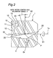
- a first plane S1 containing the screw rotor center axis 1a there are defined a first plane S1 containing the screw rotor center axis 1a, a second plane S2 which intersects orthogonally with the screw rotor center axis 1a and which further intersects with the groove portions 10 of the screw rotor 1, and a third plane S3 (see Fig. 4 ) which intersects orthogonally with the first plane S1 and the second plane S2 and which is separate from the groove portions 10 of the screw rotor 1.
- the gate rotor center axis 2a is on the third plane S3 and passes through an intersection point P among the first plane S1, the second plane S2 and the third plane S3.
- the gate rotor center axis 2a is inclined against the second plane S2 toward the same side as the groove portions 10 of the screw rotor 1.
- An inclination angle ⁇ of the gate rotor center axis 2a against the second plane S2 is, preferably, 5° to 30°.
- a length L between the gate rotor center axis 2a and the screw rotor center axis 1a is, for example, 0.7 to 1.2 as long as an outer diameter D of the gate rotor 2 (0.7D ⁇ L ⁇ 1.2D).
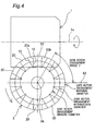
- a gate rotor engagement angle ⁇ is measured from the engagement starting side of the gate rotor 2.
- Fig. 4 shows, in the tooth portions 20 of the gate rotor 2, an engagement minimum diameter, an intermediate diameter and a maximum diameter of the gate rotor 2, the engagement being done with the groove portions 10 of the screw rotor 1. Also in a tooth portion 20, a side face on the downstream side of the rotational direction of the gate rotor 2 is assumed as a leading-side side face 20a while a side face on the upstream side of the rotational direction of the gate rotor 2 is assumed as an unleading-side side face 20b.
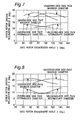
- Figs. 5 to 8 show relationships between the gate rotor engagement angle ⁇ (see Fig. 4 ) and the screw rotor groove inclination angle ⁇ when the inclination angle ⁇ of the gate rotor center axis 2a (see Fig. 2 ) is changed as 0°, 2.5°, 5° and 7.5°, plotting those concerning engagement maximum diameters and intermediate diameters (see Fig. 4 ) of the gate rotor 2 with respect to the leading-side side face 20a and the unleading-side side face 20b (see Fig. 4 ), respectively.
- the number of the groove portions 10 of the screw rotor 1 is three, and the number of the tooth portions 20 of the gate rotor 2 is twelve.
- the screw rotor groove inclination angle ⁇ refers to an angle ⁇ formed by the side face 11 of a groove portion 10 of the screw rotor 1 against a plane St which orthogonally intersects with the rotational direction (indicated by an arrow RG) of the gate rotor 2 (i.e. a circumferential direction of the gate rotor 2) in a contact portion with the side face 11 of the groove portion 10 of the screw rotor 1.
- the screw rotor groove inclination angle ⁇ is expressed in positive values (+ direction) on the gate rotor rotational direction (arrow RG direction) side, and in negative values (- direction) on the side opposite to the gate rotor rotational direction (arrow RG direction).
- Fig. 5 shows a chart when the inclination angle ⁇ of the gate rotor center axis 2a is 0°, plotting variation widths of the screw rotor groove inclination angle ⁇ with respect to engagement maximum diameters and intermediate diameters of the gate rotor 2 in the leading-side side face 20a and the unleading-side side face 20b, respectively.
- Fig. 6 shows a chart when the inclination angle ⁇ of the gate rotor center axis 2a is 2.5°, where variation widths of the screw rotor groove inclination angle ⁇ are smaller than those of the screw rotor groove inclination angle ⁇ shown in Fig. 5 .
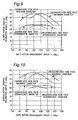
- Fig. 7 shows a chart when the inclination angle of the gate rotor center axis 2a is 5°, where as the gate rotor engagement angle ⁇ becomes larger, the screw rotor groove inclination angle ⁇ of the leading-side side face 20a becomes smaller while the screw rotor groove inclination angle ⁇ of the unleading-side side face 20b becomes larger, thus allowing the blow hole to become smaller.
- Fig. 8 shows a chart when the inclination angle of the gate rotor center axis 2a is 7.5°, where as the gate rotor engagement angle ⁇ becomes larger, the screw rotor groove inclination angle ⁇ of the leading-side side face 20a becomes noticeably smaller in comparison to Fig. 7 , while the screw rotor groove inclination angle ⁇ of the unleading-side side face 20b becomes noticeably larger in comparison to Fig. 7 , thus allowing the blow hole to become even smaller.
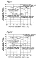
- Figs. 9 to 12 show relationships between the gate rotor engagement angle ⁇ (see Fig. 4 ) and the screw rotor groove inclination angle ⁇ when the inclination angle ⁇ of the gate rotor center axis 2a (see Fig. 2 ) is changed as 0°, 5°, 10° and 15°, plotting those concerning engagement maximum diameters and intermediate diameters (see Fig. 4 ) of the gate rotor 2 with respect to the leading-side side face 20a and the unleading-side side face 20b (see Fig. 4 ), respectively.
- the number of the groove portions 10 of the screw rotor 1 is six
- the number of the tooth portions 20 of the gate rotor 2 is twelve.
- Fig. 9 shows a chart when the inclination angle ⁇ of the gate rotor center axis 2a is 0°, where the screw rotor groove inclination angle ⁇ shows larger variation widths of the engagement maximum diameters and intermediate diameters of the gate rotor 2 with respect to the leading-side side face 20a and the unleading-side side face 20b, respectively.
- Fig. 10 shows a chart when the inclination angle ⁇ of the gate rotor center axis 2a is 5°, where variation widths of the screw rotor groove inclination angle ⁇ are smaller than those of the screw rotor groove inclination angle ⁇ shown in Fig. 9 .
- Fig. 11 shows a chart when the inclination angle of the gate rotor center axis 2a is 10°, where as the gate rotor engagement angle ⁇ becomes larger, the screw rotor groove inclination angle ⁇ of the leading-side side face 20a becomes smaller while the screw rotor groove inclination angle ⁇ of the unleading-side side face 20b becomes larger, thus allowing the blow hole to become smaller.
- Fig. 12 shows a chart when the inclination angle of the gate rotor center axis 2a is 15°, where as the gate rotor engagement angle ⁇ becomes larger, the screw rotor groove inclination angle ⁇ of the leading-side side face 20a becomes noticeably smaller in comparison to Fig. 11 , while the screw rotor groove inclination angle ⁇ of the unleading-side side face 20b becomes noticeably larger in comparison to Fig. 11 , thus allowing the blow hole to become even smaller.
- seal portions 21a, 21b of the tooth portion 20 of the gate rotor 2 to be in contact with the groove portion 10 of the screw rotor 1 are formed each into a curved-surface shape.
- a leading-side seal portion 21a is formed at the leading-side side face 20a of the tooth portion 20, while an unleading-side seal portion 21b is formed at the unleading-side side face 20b of the tooth portion 20.
- the screw rotor 1 moves along a downward-pointed arrow direction, while the gate rotor 2 moves along a leftward-pointed arrow direction.
- blow holes (leak clearances) 40, 50 shown by hatching are present.
- a leading-side blow hole 40 (shown by hatching) is present on an upstream side (compression chamber 30 side shown by hatching) of the leading-side seal portion 21a in the moving direction of the screw rotor 1
- an unleading-side blow hole 50 (shown by hatching) is present on an upstream side (the compression chamber 30 side) of the unleading-side seal portion 21b in the moving direction of the screw rotor 1.
- the fluid compressed in the compression chamber 30 passes through the blow holes 40, 50 to leak outside the casing 3 (shown by imaginary line).
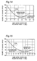
- Figs. 14 and 15 show relationships between the inclination angle ⁇ of the gate rotor center axis 2a (see Fig. 2 ) and the degree of leakage effect, plotting a degree of leakage effect of the leading-side blow hole 40 (see Fig. 13 ), a degree of leakage effect of the unleading-side blow hole 50 (see Fig. 13 ), and a total of degrees of leakage effects of the leading-side blow hole 40 and the unleading-side blow hole 50.
- degree of leakage effect refers to a ratio obtained by correcting areas of the leading-side blow hole 40 and the unleading-side blow hole 50 to leak amounts, respectively, and by assuming that the degree of leakage effect is 100 when the inclination angle ⁇ of the gate rotor center axis 2a is 0° (as in the conventional case).
- Fig. 14 shows degrees of leakage effect when the number of groove portions 10 of the screw rotor 1 is three and the number of tooth portions 20 of the gate rotor 2 is twelve.
- the inclination angle ⁇ of the gate rotor center axis 2a is around 7°, the degree of leakage effect comes to a minimum, so that the compression efficiency is improved.
- Fig. 15 shows degrees of leakage effect when the number of groove portions 10 of the screw rotor 1 is six and the number of tooth portions 20 of the gate rotor 2 is twelve.
- the inclination angle ⁇ of the gate rotor center axis 2a is around 16°, the degree of leakage effect comes to a minimum, so that the compression efficiency is improved.
- the variation width of the inclination angle of the side faces 11 of the groove portion 10 of the screw rotor 1 to be in contact with the tooth portion 20 of the gate rotor 2, the inclination being against the circumferential direction of the gate rotor 2 and the variation width measuring from axial one end of the screw rotor 1 to the other end of the screw rotor 1, is set smaller, as compared with the variation width resulting when the gate rotor center axis 2a is parallel to the second plane S2 at which the gate rotor center axis 2a orthogonally intersects with the screw rotor center axis 1a.
- the term, “circumferential direction of the gate rotor 2,” can be reworded as the rotational direction of the tooth portion 20 of the gate rotor 2 to be in contact with the side faces 11 of the groove portion 10 of the screw rotor 1.
- the term, “variation width of the screw rotor 1 from one axial end to the other axial end,” refers to a variation width of the inclination angles of all the groove portions 10 from the one axial end to the other axial end of the screw rotor 1 to be concurrently in contact with the tooth portions 20 of the gate rotor 2.
- edge angles ⁇ 1, ⁇ 2 (see Fig. 13 ) of the seal portions of the gate rotor 2 to be engaged with the side faces of the groove portions 10 of the screw rotor 1 can be made obtuse, so that the blow holes (leak clearances) present at engagement portions between the groove portions 10 of the screw rotor 1 and the tooth portions 20 of the gate rotor 2 can be made smaller.
- the compression efficiency can be improved.
- wear of the seal portions of the gate rotor 2 can be reduced, allowing an improvement in durability to be achieved.
- the angle of side faces of the groove portions 10 of the screw rotor 1 to be in contact with the tooth portions 20 of the gate rotor 2 is varied by making the gate rotor center axis 2a inclined against a plane orthogonally intersecting with the screw rotor center axis 1a.
- the inclination angle ⁇ of the gate rotor center axis 2a is 5° - 30°.
- the variation width of the screw rotor groove inclination angle ⁇ can be made even smaller.
- seal portions 21a, 21b of the tooth portions 20 of the gate rotor 2 to be in contact with the groove portions 10 of the screw rotor 1 are formed into a curved-surface shape, leaks of the compressed fluid from engagement portions between the tooth portions 20 of the gate rotor 2 and the groove portions 10 of the screw rotor 1 can be reduced, so that the compression efficiency can be improved. Besides, wear resistance of the engagement portions between the tooth portions 20 of the gate rotor 2 and the groove portions 10 of the screw rotor 1 can be improved.
- the seal portions 21a, 21b of the gate rotor 2 can be formed into a curved-surface shape. More specifically, maximum and minimum values of the inclination angle can be fulfilled by machining the groove portions 10 of the screw rotor 1 with an end mill and by forming the seal portions 21a, 21b of the tooth portions 20 of the gate rotor 2 into a curved-surface shape with an end mill.
- the present invention is not limited to the above-described embodiment.
- the number of the gate rotors 2 may be freely increased or decreased.
- the seal portions 21a, 21b of the tooth portions 20 of the gate rotor 2 to be in contact with the groove portions 10 of the screw rotor 1 may also be formed into an acute-angle shape.
Landscapes
- Engineering & Computer Science (AREA)
- Mechanical Engineering (AREA)
- General Engineering & Computer Science (AREA)
- Applications Or Details Of Rotary Compressors (AREA)
Applications Claiming Priority (2)
| Application Number | Priority Date | Filing Date | Title |
|---|---|---|---|
| JP2006316793A JP4169069B2 (ja) | 2006-11-24 | 2006-11-24 | 圧縮機 |
| PCT/JP2007/071623 WO2008062672A1 (en) | 2006-11-24 | 2007-11-07 | Compressor |
Publications (2)
| Publication Number | Publication Date |
|---|---|
| EP2090784A1 true EP2090784A1 (de) | 2009-08-19 |
| EP2090784A4 EP2090784A4 (de) | 2014-01-22 |
Family
ID=39429610
Family Applications (1)
| Application Number | Title | Priority Date | Filing Date |
|---|---|---|---|
| EP07831354.1A Withdrawn EP2090784A4 (de) | 2006-11-24 | 2007-11-07 | Verdichter |
Country Status (5)
| Country | Link |
|---|---|
| US (1) | US8105059B2 (de) |
| EP (1) | EP2090784A4 (de) |
| JP (1) | JP4169069B2 (de) |
| CN (1) | CN101535650B (de) |
| WO (1) | WO2008062672A1 (de) |
Families Citing this family (7)
| Publication number | Priority date | Publication date | Assignee | Title |
|---|---|---|---|---|
| US8309265B2 (en) | 2003-09-12 | 2012-11-13 | Hitachi, Ltd. | Electrolyte membrane for fuel cells, its production and fuel cell using the same |
| US8022032B2 (en) | 2004-11-19 | 2011-09-20 | Smithkline Beecham Corporation | Method for customized dispensing of variable dose drug combination products for individualizing of therapies |
| JP2011038484A (ja) * | 2009-08-13 | 2011-02-24 | Mitsui Seiki Kogyo Co Ltd | スクリューコンプレッサのゲートロータの稜線廻りの構造 |
| US9057373B2 (en) | 2011-11-22 | 2015-06-16 | Vilter Manufacturing Llc | Single screw compressor with high output |
| CN103122857B (zh) * | 2012-09-29 | 2015-11-18 | 苏州利森空调制冷有限公司 | 一种压缩机用的带螺钉状转子的压缩组件 |
| JP7364949B2 (ja) * | 2022-03-28 | 2023-10-19 | ダイキン工業株式会社 | シングルスクリュー圧縮機 |
| JP7360065B1 (ja) | 2022-03-28 | 2023-10-12 | ダイキン工業株式会社 | スクリュー圧縮機及び冷凍装置 |
Family Cites Families (11)
| Publication number | Priority date | Publication date | Assignee | Title |
|---|---|---|---|---|
| US1989552A (en) | 1934-01-03 | 1935-01-29 | Paul E Good | Rotary compressor |
| FR1601531A (de) * | 1968-12-27 | 1970-08-24 | ||
| GB1388537A (en) * | 1973-03-13 | 1975-03-26 | Zimmern B | Rotary positive-displacement machines for compression or expansion of a fluid |
| JPS5755881B2 (de) | 1973-03-20 | 1982-11-26 | ||
| DE2315503C2 (de) * | 1973-03-28 | 1983-03-31 | Omphale S.A., Puteaux, Hauts-de-Seine | Außenachsige Rotationskolben-Verdichtungs-oder Expansionsmaschine |
| US4179250A (en) * | 1977-11-04 | 1979-12-18 | Chicago Pneumatic Tool Company | Thread construction for rotary worm compression-expansion machines |
| FR2444180A1 (fr) * | 1978-12-13 | 1980-07-11 | Zimmern Bernard | Machines volumetriques a vis et pignon comprenant plusieurs aretes de contact |
| FR2624215B1 (fr) | 1987-12-03 | 1990-05-11 | Zimmern Bernard | Pignons flottants pour machine a vis haute pression |
| AU1016801A (en) * | 1999-10-26 | 2001-05-08 | Shiliang Zha | A single screw compressor |
| CN1079501C (zh) * | 1999-10-26 | 2002-02-20 | 查世樑 | 单螺杆压缩机 |
| CN1532404A (zh) * | 2003-03-24 | 2004-09-29 | 朱妙睿 | 同轴多节蜗杆式空气压缩机 |
-
2006
- 2006-11-24 JP JP2006316793A patent/JP4169069B2/ja not_active Expired - Fee Related
-
2007
- 2007-11-07 WO PCT/JP2007/071623 patent/WO2008062672A1/ja not_active Ceased
- 2007-11-07 CN CN2007800411613A patent/CN101535650B/zh not_active Expired - Fee Related
- 2007-11-07 US US12/515,517 patent/US8105059B2/en not_active Expired - Fee Related
- 2007-11-07 EP EP07831354.1A patent/EP2090784A4/de not_active Withdrawn
Also Published As
| Publication number | Publication date |
|---|---|
| EP2090784A4 (de) | 2014-01-22 |
| CN101535650A (zh) | 2009-09-16 |
| CN101535650B (zh) | 2011-08-03 |
| US20100074785A1 (en) | 2010-03-25 |
| JP2008128167A (ja) | 2008-06-05 |
| JP4169069B2 (ja) | 2008-10-22 |
| US8105059B2 (en) | 2012-01-31 |
| WO2008062672A1 (en) | 2008-05-29 |
Similar Documents
| Publication | Publication Date | Title |
|---|---|---|
| EP2090784A1 (de) | Verdichter | |
| US20220136504A1 (en) | Rotor pair for a compression block of a screw machine | |
| US6779993B2 (en) | Rotor profile for screw compressors | |
| US20120014825A1 (en) | Roots type fluid machine | |
| US20040037730A1 (en) | Single-screw compressor | |
| EP2078863B1 (de) | Verdichter | |
| CN100402855C (zh) | 涡旋压缩机 | |
| US6499978B2 (en) | Scroll compressor having different wrap thicknesses | |
| CN100359176C (zh) | 涡旋式流体机械 | |
| EP2148093B1 (de) | Schraubenverdichter | |
| WO2010013375A1 (ja) | ロータリ圧縮機 | |
| US20230392598A1 (en) | Screw Compressor and Screw Rotor | |
| JP4461016B2 (ja) | ヘリカルスクリューロータコンプレッサ | |
| EP2236833A1 (de) | Schraubenverdichter | |
| JP4325702B2 (ja) | スクリュー圧縮機 | |
| EP2857688B1 (de) | Rotationsverdichter | |
| JP2008248823A (ja) | スクロール流体機械 | |
| JP2008150982A (ja) | ベーンロータリー圧縮機 | |
| JP2001193679A (ja) | 気体圧縮機 | |
| JP2010185431A (ja) | Zスクリューコンプレッサにおけるリーク損失低減方法 | |
| JPH04279793A (ja) | ベ−ン圧縮機 |
Legal Events
| Date | Code | Title | Description |
|---|---|---|---|
| PUAI | Public reference made under article 153(3) epc to a published international application that has entered the european phase |
Free format text: ORIGINAL CODE: 0009012 |
|
| 17P | Request for examination filed |
Effective date: 20090522 |
|
| AK | Designated contracting states |
Kind code of ref document: A1 Designated state(s): AT BE BG CH CY CZ DE DK EE ES FI FR GB GR HU IE IS IT LI LT LU LV MC MT NL PL PT RO SE SI SK TR |
|
| DAX | Request for extension of the european patent (deleted) | ||
| A4 | Supplementary search report drawn up and despatched |
Effective date: 20140103 |
|
| RIC1 | Information provided on ipc code assigned before grant |
Ipc: F04C 18/54 20060101AFI20131218BHEP Ipc: F04C 18/52 20060101ALI20131218BHEP |
|
| STAA | Information on the status of an ep patent application or granted ep patent |
Free format text: STATUS: THE APPLICATION HAS BEEN WITHDRAWN |
|
| 18W | Application withdrawn |
Effective date: 20170607 |