EP2090837A1 - Plaque de matériau isolant pour tuyaux de chauffage et/ou de refroidissement - Google Patents
Plaque de matériau isolant pour tuyaux de chauffage et/ou de refroidissement Download PDFInfo
- Publication number
- EP2090837A1 EP2090837A1 EP08002912A EP08002912A EP2090837A1 EP 2090837 A1 EP2090837 A1 EP 2090837A1 EP 08002912 A EP08002912 A EP 08002912A EP 08002912 A EP08002912 A EP 08002912A EP 2090837 A1 EP2090837 A1 EP 2090837A1
- Authority
- EP
- European Patent Office
- Prior art keywords
- plate
- pipe support
- support webs
- board according
- layer
- Prior art date
- Legal status (The legal status is an assumption and is not a legal conclusion. Google has not performed a legal analysis and makes no representation as to the accuracy of the status listed.)
- Granted
Links
- 238000010438 heat treatment Methods 0.000 title claims description 15
- 238000001816 cooling Methods 0.000 title claims description 12
- 239000011810 insulating material Substances 0.000 title description 3
- 239000010410 layer Substances 0.000 claims description 52
- 238000009413 insulation Methods 0.000 claims description 37
- 239000004566 building material Substances 0.000 claims description 5
- 239000012790 adhesive layer Substances 0.000 claims description 3
- 229920006248 expandable polystyrene Polymers 0.000 claims description 3
- 239000004033 plastic Substances 0.000 claims description 3
- 230000000284 resting effect Effects 0.000 claims description 2
- 239000004035 construction material Substances 0.000 abstract 1
- 238000009434 installation Methods 0.000 description 4
- 238000004873 anchoring Methods 0.000 description 2
- 238000004519 manufacturing process Methods 0.000 description 2
- 230000007704 transition Effects 0.000 description 2
- 239000000853 adhesive Substances 0.000 description 1
- 230000001070 adhesive effect Effects 0.000 description 1
- 230000002411 adverse Effects 0.000 description 1
- 239000011248 coating agent Substances 0.000 description 1
- 238000000576 coating method Methods 0.000 description 1
- 230000000295 complement effect Effects 0.000 description 1
- 239000006260 foam Substances 0.000 description 1
- 239000011888 foil Substances 0.000 description 1
- 239000000203 mixture Substances 0.000 description 1
Images

Classifications
-
- F—MECHANICAL ENGINEERING; LIGHTING; HEATING; WEAPONS; BLASTING
- F24—HEATING; RANGES; VENTILATING
- F24D—DOMESTIC- OR SPACE-HEATING SYSTEMS, e.g. CENTRAL HEATING SYSTEMS; DOMESTIC HOT-WATER SUPPLY SYSTEMS; ELEMENTS OR COMPONENTS THEREFOR
- F24D3/00—Hot-water central heating systems
- F24D3/12—Tube and panel arrangements for ceiling, wall, or underfloor heating
- F24D3/14—Tube and panel arrangements for ceiling, wall, or underfloor heating incorporated in a ceiling, wall or floor
- F24D3/141—Tube mountings specially adapted therefor
- F24D3/142—Tube mountings specially adapted therefor integrated in prefab construction elements
-
- E—FIXED CONSTRUCTIONS
- E04—BUILDING
- E04C—STRUCTURAL ELEMENTS; BUILDING MATERIALS
- E04C2/00—Building elements of relatively thin form for the construction of parts of buildings, e.g. sheet materials, slabs, or panels
- E04C2/02—Building elements of relatively thin form for the construction of parts of buildings, e.g. sheet materials, slabs, or panels characterised by specified materials
- E04C2/10—Building elements of relatively thin form for the construction of parts of buildings, e.g. sheet materials, slabs, or panels characterised by specified materials of wood, fibres, chips, vegetable stems, or the like; of plastics; of foamed products
- E04C2/20—Building elements of relatively thin form for the construction of parts of buildings, e.g. sheet materials, slabs, or panels characterised by specified materials of wood, fibres, chips, vegetable stems, or the like; of plastics; of foamed products of plastics
- E04C2/205—Building elements of relatively thin form for the construction of parts of buildings, e.g. sheet materials, slabs, or panels characterised by specified materials of wood, fibres, chips, vegetable stems, or the like; of plastics; of foamed products of plastics of foamed plastics, or of plastics and foamed plastics, optionally reinforced
-
- E—FIXED CONSTRUCTIONS
- E04—BUILDING
- E04C—STRUCTURAL ELEMENTS; BUILDING MATERIALS
- E04C2/00—Building elements of relatively thin form for the construction of parts of buildings, e.g. sheet materials, slabs, or panels
- E04C2/44—Building elements of relatively thin form for the construction of parts of buildings, e.g. sheet materials, slabs, or panels characterised by the purpose
- E04C2/52—Building elements of relatively thin form for the construction of parts of buildings, e.g. sheet materials, slabs, or panels characterised by the purpose with special adaptations for auxiliary purposes, e.g. serving for locating conduits
- E04C2/521—Building elements of relatively thin form for the construction of parts of buildings, e.g. sheet materials, slabs, or panels characterised by the purpose with special adaptations for auxiliary purposes, e.g. serving for locating conduits serving for locating conduits; for ventilating, heating or cooling
- E04C2/525—Building elements of relatively thin form for the construction of parts of buildings, e.g. sheet materials, slabs, or panels characterised by the purpose with special adaptations for auxiliary purposes, e.g. serving for locating conduits serving for locating conduits; for ventilating, heating or cooling for heating or cooling
-
- Y—GENERAL TAGGING OF NEW TECHNOLOGICAL DEVELOPMENTS; GENERAL TAGGING OF CROSS-SECTIONAL TECHNOLOGIES SPANNING OVER SEVERAL SECTIONS OF THE IPC; TECHNICAL SUBJECTS COVERED BY FORMER USPC CROSS-REFERENCE ART COLLECTIONS [XRACs] AND DIGESTS
- Y02—TECHNOLOGIES OR APPLICATIONS FOR MITIGATION OR ADAPTATION AGAINST CLIMATE CHANGE
- Y02B—CLIMATE CHANGE MITIGATION TECHNOLOGIES RELATED TO BUILDINGS, e.g. HOUSING, HOUSE APPLIANCES OR RELATED END-USER APPLICATIONS
- Y02B30/00—Energy efficient heating, ventilation or air conditioning [HVAC]
Definitions
- the invention relates to an insulation panel for heating pipes and / or cooling pipes.
- the invention further relates to a plate system with at least one insulating plate, at least one heating tube and / or cooling tube and with tube holders.
- the insulation board according to the invention is used in particular for relation askêtsammlungungsrohe.
- the pipes are laid on the insulation board and fixed to the insulation board.
- the fixation of the tubes is advantageously carried out with the help of tube holders or tube clips, which are preferably U-shaped and with so-called Tackervorraumen - the tubes across - are introduced into the insulation board.
- the invention is the technical problem of specifying an insulation plate of the type mentioned, the versatile and can be used variably and ensures optimum heating and / or cooling performance.
- the invention teaches an insulating plate for heating pipes and / or cooling tubes, the plate having at its top a plurality of Rohrauflagestegen and wherein the resting on the Rohrauflagestegen tubes in the spaces between the pipe support webs with their plate-side tube bottom in a on the Plate coatable building material, especially embedable in screed, in particular are fully embeddable.
- - Building material means in the context of the invention, a building material mixture.
- the insulating board is polygonal, in particular rectangular designed and the pipe support webs extend obliquely to one side, in particular to a rectangular side of the plate. It is within the scope of the invention that the insulation board according to the invention is rectangular, in particular square.
- pipe support webs means that after laying the pipes rest on these pipe support webs of the board.
- the tubes have exclusive contact with these pipe support webs or no contact with the other areas of the top plate.
- the tubes or the plate-side tube bottoms of the tubes are arranged spaced from the plate surface.
- the pipes are fixed to and / or during their installation on the insulation board, including preferably tube holder or pipe clips are used, which are anchored in the insulation board.
- Pipe holder or pipe clips means within the scope of the invention, a fixing element for the pipe, the one Receiving for the tube and at least one fixing element or anchoring element for anchoring in the insulation board.
- these are U-shaped tube holders, which are expediently anchored with barbs in the insulating board.
- a so-called tacking device is recommended for inserting the pipe holder into the insulation board.
- Such tacker devices and such pipe holders are well known in the art.
- the insulation board according to the invention has proven itself in particular in relation to the above-described laying / fixing of the tubes.
- the pipe support webs according to the invention run obliquely with respect to all the rectangular sides of the plate. - It is within the scope of the invention that the pipe support webs are distributed over the entire top of the plate or virtually on the entire top of the plate. With the term obliquely with respect to a side, in particular a rectangle side, it is meant in the context of the invention that the pipe support webs enclose an angle deviating from 90 ° with the side, in particular the rectangle side.
- the angle between the pipe support webs or the longitudinal direction of the pipe support webs and a plate side, in particular a rectangular side is 10 to 80 °, in particular 20 to 70 °, preferably 30 to 60 ° and preferably 35 to 55 °.
- the angle ⁇ between the pipe support webs and the plate side or rectangular side is 40 to 50 °, in particular 45 ° or about 45 °. The pipe support webs then run diagonally across the top of the plate.
- the pipe support webs are arranged parallel or substantially parallel to each other. According to recommended embodiment, at least a portion or at least a majority of the pipe support webs equal distances from each other. Preferably, all pipe support webs of a plate at equal distances from each other.
- the pipe support webs in cross-section U-shaped or substantially U-shaped.
- the pipe support webs are characterized by large radii at their maximum and in the region of their transitions to the disk surface. It is recommended that all pipe support webs have the same shape or have substantially the same shape.
- the Rohrauflagstege a height of 1.5 to 8 mm, in particular from 1.5 to 6 mm, preferably from 2 to 4.5 mm and preferably from 2.5 to 3.5 mm.
- the height of the pipe support webs is 3 mm or about 3 mm. Height means the distance of the maximum of the pipe support webs from the rest of the disk surface.
- all pipe support webs have the same height or substantially the same height.
- the pipe support webs have over their longitudinal extent a constant height or a substantially constant height.
- the width of the pipe support webs is 1.5 to 4 mm, preferably 2 to 3 mm.
- the plate could therefore have, for example, a low profiling or micro-profiling on its upper side next to the pipe support webs, but the elevations of this profiling expediently have a lower height than the pipe support webs. It is within the scope of the invention that the pipe support webs are the highest elevations on the top of the plate. - Many known from the prior art insulation boards have on their surface individual knobs, between which in particular the laid pipes are to be kept. According to a particularly preferred embodiment of the invention, the top of the insulation boards according to the invention is formed free of such knobs or knob-free. According to the recommended embodiment of the invention, the pipe support webs or the longitudinal extension of the pipe support webs are not interrupted by nubs.
- the insulating board on a lower-side insulating layer and arranged on the top of the insulating layer or fixed support layer, in particular support film, wherein the pipe support webs are formed in the support layer or in the support film.
- support layer or support film is meant that the pipes to be laid directly on the support layer or support film.
- the thickness of the support layer or support film is less or substantially less than the thickness of the insulating layer.
- the support layer is a deep-drawn support film.
- the overlay layer or overlay foil is recommended to be laminated onto the insulating layer.
- the pipe support webs are provided only in the support layer or support film and the support layer / support film is applied to the flat or substantially flat insulating layer on its upper side.
- the pipe support webs in the support layer or support film provided and at the top of the insulating layer webs are also present, which engage in the finished or assembled state of the plate on the underside of the support layer / support film in the hollow internally formed hollow support webs complementary. Appropriately, this intervention takes place positively.
- the insulating layer consists of a foamed plastic, in particular foamed polystyrene. In the production of the insulation layer can be moved so that the insulating layer is separated out of a foam block.
- a particularly preferred embodiment of the invention is characterized in that the overlay layer projects beyond the insulating layer on at least one side of the panel and that the protruding section of the overlay layer is a connecting element for connecting the panel to an adjacent insulating panel.
- the protruding portions are provided on two adjacent sides of the insulation board. It is within the scope of the invention that a projecting portion of the support layer rests in the installed state of a plurality of plates on top of the associated adjacent plate.
- the support is expediently carried out on a connecting portion of the upper side of the adjacent plate whose width corresponds to the width of the projecting portion of the other plate. It is understood that on a plate side with connecting portion no projecting portion of the support layer is provided.
- the support layer or support film is reset by the width of the connecting portion, so that the protruding portion of an adjacent plate rests on the insulating layer. It is recommended that an overhanging portion of the support layer is at least partially provided with an adhesive or with an adhesive layer on the underside.
- the protruding portion is therefore on top of the adjacent Glued plate or on top of the connecting portion of the adjacent plate.
- the pipe support webs end at least one side of a plate at a distance in front of the plate edge. It is within the scope of the invention that the pipe support webs end at a plate side with connecting portion in front of the connecting portion.
- the pipe support webs end at two adjacent sides of a plate at a distance from the edge of the plate. It is within the scope of the invention that the pipe support webs end at the plate sides at a distance in front of the plate edge at which no projecting portion of the support layer is present.
- the invention further teaches a plate system with at least one insulating plate, in particular of the type described above, at least one heating tube and / or cooling tube and tube holders, wherein the tube is fixed with the tube holders on the plate and wherein the plate on her Top side a plurality of pipe support webs, in particular of the type described above, on which rest the pipes in the mounted / fixed state.
- the plate-side tube bottom of the tubes is spaced from the top of the plate, so that the tubes with their plate-side tube bottom in a coatable on the plate building material, especially in screed embedding, in particular are fully embeddable.
- the invention is based on the finding that a functionally reliable and precise installation of pipes, in particular floor heating pipes, is possible with the aid of an insulating panel according to the invention. Due to the inventive design of the insulation board ensures that an applied with laid pipes screed coating the pipes over their entire circumference or that the pipes are embedded over their entire circumference in the screed layer. When using an inventive Insulation board for a heating or cooling system can be achieved a very excellent heating or cooling performance.
- the invention is based on the knowledge that due to the inventive design of the insulation board optimum temperature transition can be made on the screed. It should also be emphasized that an insulation panel according to the invention can be produced in a relatively simple, inexpensive and thus cost-effective manner.
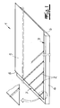
- the invention relates to an insulating panel 1 for the installation of heating pipes or cooling pipes, in particular for the installation of floor heating pipes.
- the plate 1 is rectangular, in particular square.
- the plate 1 has on its upper side a plurality of pipe support webs 2. On these Rohrauflagestegen 2, the tubes 3 are placed at their laying.
- the pipe support webs 2 extend obliquely or diagonally with respect to the rectangle sides of the plate 1.
- the pipe support webs 2 each enclose an angle of 45 ° with a rectangle side of the board. EmpfohleneIER and in the embodiment, the pipe support webs 2 are virtually distributed over the entire top of the plate 1.
- all pipe support webs 2 are arranged parallel to each other and all pipe support webs 2 have equal distances to each other.
- the pipe support webs are expediently formed in cross-section U-shaped.
- all pipe support webs 2 have the same shape.
- the pipe support webs 2 as in the embodiment all have the same height or substantially the same height and that each pipe support web 2 has the same height or substantially the same height over its longitudinal extent.
- only the pipe support webs 2 according to the invention are provided as protruding from the top of the plate 1 surveys. Otherwise, the plate 1 is formed elevation free at its top.
- the plate 1 has a lower-side insulating layer 4 and arranged on the upper side of the insulating layer 4 support sheet 5.
- the pipe support webs 2 are formed only in the support sheet 5 and this profiled support sheet 5 rests on the insulating layer 4, which is flat on its upper side.
- Insulation layer 4 is recommended to be made of foamed polystyrene.
- the support film 5 may be a deep-drawn support film 5 made of plastic. In the Fig. 1 It can be seen that the thickness of the insulating material layer 4 is substantially greater than the thickness of the support film 5.
- the support film 5 projects beyond the insulating material layer 4 on two adjoining sides of the panel 1.
- the protruding portions 6 of the support film 5 are in the laid state of the plates 1 on the adjacent plates 1.
- the protruding portions 6 are preferably provided on its underside with an adhesive layer.
- the support film 5 ends at a distance in front of the plate edge, so that here connecting portions 7 of the insulation layer 4 result, on which the protruding portions 6 adjacent plates 1 rest.
- pipe support webs 2 end with a corresponding distance in front of the plate edge.
- Fig. 2 shows four plates to be joined together according to the invention 1.
- the protruding portions 6 of the plates have not yet been brought to rest on the connecting portions 7 of the adjacent plates 1, so that the plates 1 are still arranged with a corresponding distance from each other.
- the plates 1 are laid with the proviso that the pipe support webs 2 of two adjacent plates are aligned with each other or connect to each other. Is in Fig. 2 recognizable.
- Fig. 2 also laid pipes 3 are shown, which in the embodiment belong to a floor heating. It can be seen that the pipe support webs 2 extend obliquely to the laid pipes 3, so that always a corresponding distance between the tubes 3 and the top of the plate 1 is ensured.
- the tubes 3 can be completely, ie embedded over their entire circumference in the screed layer.
Landscapes
- Engineering & Computer Science (AREA)
- Architecture (AREA)
- Life Sciences & Earth Sciences (AREA)
- Mechanical Engineering (AREA)
- Civil Engineering (AREA)
- Structural Engineering (AREA)
- Physics & Mathematics (AREA)
- Thermal Sciences (AREA)
- Chemical & Material Sciences (AREA)
- Combustion & Propulsion (AREA)
- Wood Science & Technology (AREA)
- General Engineering & Computer Science (AREA)
- Sustainable Development (AREA)
- Steam Or Hot-Water Central Heating Systems (AREA)
- Thermal Insulation (AREA)
Priority Applications (3)
| Application Number | Priority Date | Filing Date | Title |
|---|---|---|---|
| DE502008002869T DE502008002869D1 (de) | 2008-02-16 | 2008-02-16 | Dämmstoffplatte für Heizungsrohre und/oder Kühlrohre |
| EP08002912A EP2090837B1 (fr) | 2008-02-16 | 2008-02-16 | Plaque de matériau isolant pour tuyaux de chauffage et/ou de refroidissement |
| AT08002912T ATE502262T1 (de) | 2008-02-16 | 2008-02-16 | Dämmstoffplatte für heizungsrohre und/oder kühlrohre |
Applications Claiming Priority (1)
| Application Number | Priority Date | Filing Date | Title |
|---|---|---|---|
| EP08002912A EP2090837B1 (fr) | 2008-02-16 | 2008-02-16 | Plaque de matériau isolant pour tuyaux de chauffage et/ou de refroidissement |
Publications (2)
| Publication Number | Publication Date |
|---|---|
| EP2090837A1 true EP2090837A1 (fr) | 2009-08-19 |
| EP2090837B1 EP2090837B1 (fr) | 2011-03-16 |
Family
ID=39650565
Family Applications (1)
| Application Number | Title | Priority Date | Filing Date |
|---|---|---|---|
| EP08002912A Expired - Fee Related EP2090837B1 (fr) | 2008-02-16 | 2008-02-16 | Plaque de matériau isolant pour tuyaux de chauffage et/ou de refroidissement |
Country Status (3)
| Country | Link |
|---|---|
| EP (1) | EP2090837B1 (fr) |
| AT (1) | ATE502262T1 (fr) |
| DE (1) | DE502008002869D1 (fr) |
Cited By (1)
| Publication number | Priority date | Publication date | Assignee | Title |
|---|---|---|---|---|
| WO2012034753A3 (fr) * | 2010-09-15 | 2012-11-01 | Evonik Degussa Gmbh | Panneau de façade |
Citations (2)
| Publication number | Priority date | Publication date | Assignee | Title |
|---|---|---|---|---|
| US4338994A (en) * | 1980-01-28 | 1982-07-13 | Bernd Hewing | Modular panel heater having improved holder devices |
| FR2883314A1 (fr) * | 2005-03-18 | 2006-09-22 | Rehau Sa | Plaque isolante pour le chauffage par le sol comportant une pluralite de groupes de plots definissant entre eux des espaces libres pour le positionnement des pieds. |
-
2008
- 2008-02-16 EP EP08002912A patent/EP2090837B1/fr not_active Expired - Fee Related
- 2008-02-16 AT AT08002912T patent/ATE502262T1/de active
- 2008-02-16 DE DE502008002869T patent/DE502008002869D1/de active Active
Patent Citations (2)
| Publication number | Priority date | Publication date | Assignee | Title |
|---|---|---|---|---|
| US4338994A (en) * | 1980-01-28 | 1982-07-13 | Bernd Hewing | Modular panel heater having improved holder devices |
| FR2883314A1 (fr) * | 2005-03-18 | 2006-09-22 | Rehau Sa | Plaque isolante pour le chauffage par le sol comportant une pluralite de groupes de plots definissant entre eux des espaces libres pour le positionnement des pieds. |
Cited By (1)
| Publication number | Priority date | Publication date | Assignee | Title |
|---|---|---|---|---|
| WO2012034753A3 (fr) * | 2010-09-15 | 2012-11-01 | Evonik Degussa Gmbh | Panneau de façade |
Also Published As
| Publication number | Publication date |
|---|---|
| DE502008002869D1 (de) | 2011-04-28 |
| ATE502262T1 (de) | 2011-04-15 |
| EP2090837B1 (fr) | 2011-03-16 |
Similar Documents
| Publication | Publication Date | Title |
|---|---|---|
| EP2742192B1 (fr) | Système composite d'isolation thermique, bâtiment avec un tel système et procédé de montage d'un système composite d'isolation thermique | |
| WO2002031290A1 (fr) | Plaque de recouvrement | |
| DE102006004755B4 (de) | Fußbodenaufbau sowie Verwendung einer Entkopplungsmatte zum Aufbau einer Fußbodenheizung | |
| DE102012001557A1 (de) | Plattenförmiges Element für Fußbodenheizungen | |
| EP1531306B1 (fr) | Plaque en plastique pour le montage de tubes dans lesquels circule un fluide | |
| DE2456836A1 (de) | Verfahren zur verlegung einer heizrohr-anordnung auf flaechen | |
| WO2004018798A2 (fr) | Plancher constitue d'elements individuels | |
| EP2090837B1 (fr) | Plaque de matériau isolant pour tuyaux de chauffage et/ou de refroidissement | |
| DE3209091A1 (de) | Verbundplatte fuer eine fussbodenheizung | |
| DE20110201U1 (de) | Trockenbau-System für eine Flächenheizung oder Flächenkühlung | |
| EP1717386B1 (fr) | Elément de plancher | |
| DE19727922C2 (de) | Rohrfixiervorrichtung für Flächenheizungsrohre, insbesondere Fußbodenheizungsrohre | |
| AT405666B (de) | Auf einen ebenen untergrund aufbringbare folie | |
| DE19801370A1 (de) | Tafelelement | |
| DE102008059459A1 (de) | Herstellverfahren für einen Fußbodenaufbau in einem Gebäuderaum, sowie Fußbodenelemente und Sockelleistenbausatz zur Durchführung des Verfahrens | |
| DE10347199A1 (de) | Beheizbares Fußbodenelement mit Oberflächenschicht | |
| DE202008007390U1 (de) | Schichtverbund als Träger für keramische, Stein- oder ähnliche Beläge | |
| DE2742429A1 (de) | Montageplatte fuer heiz- und kuehlmittelschlaeuche und deren verwendung | |
| DE202008005910U1 (de) | Montageplatte zum Fixieren von Heizrohren | |
| EP2674545B1 (fr) | Isolation comprenant des panneaux isolants avec des joints rainure-languette le long des bords | |
| DE102009013953A1 (de) | Matte für Belagskonstruktion sowie zugehörige Belagskonstruktion | |
| WO2017055368A1 (fr) | Élément de support pour éléments chauffants souples linéaires d'un chauffage de surface | |
| EP1312722B1 (fr) | Elément de construction pour une structure de plafond et structure de plafond dans un batiment | |
| DE2911982A1 (de) | Bausatz fuer fussbodenheizungen | |
| EP1516976B1 (fr) | Elément multicouche de revêtement de sol avec des rainures pour des profilés d'assemblage |
Legal Events
| Date | Code | Title | Description |
|---|---|---|---|
| PUAI | Public reference made under article 153(3) epc to a published international application that has entered the european phase |
Free format text: ORIGINAL CODE: 0009012 |
|
| AK | Designated contracting states |
Kind code of ref document: A1 Designated state(s): AT BE BG CH CY CZ DE DK EE ES FI FR GB GR HR HU IE IS IT LI LT LU LV MC MT NL NO PL PT RO SE SI SK TR |
|
| AX | Request for extension of the european patent |
Extension state: AL BA MK RS |
|
| AKX | Designation fees paid | ||
| 17P | Request for examination filed |
Effective date: 20100607 |
|
| RBV | Designated contracting states (corrected) |
Designated state(s): AT DE |
|
| GRAP | Despatch of communication of intention to grant a patent |
Free format text: ORIGINAL CODE: EPIDOSNIGR1 |
|
| GRAS | Grant fee paid |
Free format text: ORIGINAL CODE: EPIDOSNIGR3 |
|
| GRAA | (expected) grant |
Free format text: ORIGINAL CODE: 0009210 |
|
| AK | Designated contracting states |
Kind code of ref document: B1 Designated state(s): AT DE |
|
| REF | Corresponds to: |
Ref document number: 502008002869 Country of ref document: DE Date of ref document: 20110428 Kind code of ref document: P |
|
| REG | Reference to a national code |
Ref country code: DE Ref legal event code: R096 Ref document number: 502008002869 Country of ref document: DE Effective date: 20110428 |
|
| PLBE | No opposition filed within time limit |
Free format text: ORIGINAL CODE: 0009261 |
|
| STAA | Information on the status of an ep patent application or granted ep patent |
Free format text: STATUS: NO OPPOSITION FILED WITHIN TIME LIMIT |
|
| 26N | No opposition filed |
Effective date: 20111219 |
|
| REG | Reference to a national code |
Ref country code: DE Ref legal event code: R097 Ref document number: 502008002869 Country of ref document: DE Effective date: 20111219 |
|
| PGFP | Annual fee paid to national office [announced via postgrant information from national office to epo] |
Ref country code: DE Payment date: 20130206 Year of fee payment: 6 |
|
| PGFP | Annual fee paid to national office [announced via postgrant information from national office to epo] |
Ref country code: AT Payment date: 20130213 Year of fee payment: 6 |
|
| REG | Reference to a national code |
Ref country code: DE Ref legal event code: R119 Ref document number: 502008002869 Country of ref document: DE |
|
| REG | Reference to a national code |
Ref country code: AT Ref legal event code: MM01 Ref document number: 502262 Country of ref document: AT Kind code of ref document: T Effective date: 20140216 |
|
| REG | Reference to a national code |
Ref country code: DE Ref legal event code: R119 Ref document number: 502008002869 Country of ref document: DE Effective date: 20140902 |
|
| PG25 | Lapsed in a contracting state [announced via postgrant information from national office to epo] |
Ref country code: AT Free format text: LAPSE BECAUSE OF NON-PAYMENT OF DUE FEES Effective date: 20140216 |
|
| PG25 | Lapsed in a contracting state [announced via postgrant information from national office to epo] |
Ref country code: DE Free format text: LAPSE BECAUSE OF NON-PAYMENT OF DUE FEES Effective date: 20140902 |