EP1516976B1 - Elément multicouche de revêtement de sol avec des rainures pour des profilés d'assemblage - Google Patents
Elément multicouche de revêtement de sol avec des rainures pour des profilés d'assemblage Download PDFInfo
- Publication number
- EP1516976B1 EP1516976B1 EP04021868A EP04021868A EP1516976B1 EP 1516976 B1 EP1516976 B1 EP 1516976B1 EP 04021868 A EP04021868 A EP 04021868A EP 04021868 A EP04021868 A EP 04021868A EP 1516976 B1 EP1516976 B1 EP 1516976B1
- Authority
- EP
- European Patent Office
- Prior art keywords
- grooves
- resistant
- material layer
- floor
- elements
- Prior art date
- Legal status (The legal status is an assumption and is not a legal conclusion. Google has not performed a legal analysis and makes no representation as to the accuracy of the status listed.)
- Expired - Lifetime
Links
- 239000003562 lightweight material Substances 0.000 claims description 34
- 238000005299 abrasion Methods 0.000 claims description 10
- 230000001070 adhesive effect Effects 0.000 claims description 7
- 239000000853 adhesive Substances 0.000 claims description 6
- 239000004743 Polypropylene Substances 0.000 claims description 3
- -1 polypropylene Polymers 0.000 claims description 3
- 229920001155 polypropylene Polymers 0.000 claims description 3
- 239000010410 layer Substances 0.000 description 53
- 239000004575 stone Substances 0.000 description 10
- 238000007789 sealing Methods 0.000 description 8
- 239000004918 carbon fiber reinforced polymer Substances 0.000 description 6
- 239000004033 plastic Substances 0.000 description 6
- 230000002787 reinforcement Effects 0.000 description 6
- 239000004744 fabric Substances 0.000 description 5
- 239000000463 material Substances 0.000 description 5
- 238000010438 heat treatment Methods 0.000 description 4
- 239000002184 metal Substances 0.000 description 4
- 239000004570 mortar (masonry) Substances 0.000 description 4
- 230000003014 reinforcing effect Effects 0.000 description 4
- 238000004026 adhesive bonding Methods 0.000 description 3
- 238000010276 construction Methods 0.000 description 3
- 230000008719 thickening Effects 0.000 description 3
- 239000002023 wood Substances 0.000 description 3
- 229920006328 Styrofoam Polymers 0.000 description 2
- 239000000919 ceramic Substances 0.000 description 2
- 230000005494 condensation Effects 0.000 description 2
- 238000009833 condensation Methods 0.000 description 2
- 239000006260 foam Substances 0.000 description 2
- 239000011888 foil Substances 0.000 description 2
- 239000011521 glass Substances 0.000 description 2
- 239000011229 interlayer Substances 0.000 description 2
- 239000000123 paper Substances 0.000 description 2
- 239000008261 styrofoam Substances 0.000 description 2
- 239000000758 substrate Substances 0.000 description 2
- XLYOFNOQVPJJNP-UHFFFAOYSA-N water Substances O XLYOFNOQVPJJNP-UHFFFAOYSA-N 0.000 description 2
- 239000011324 bead Substances 0.000 description 1
- 230000005540 biological transmission Effects 0.000 description 1
- 239000012876 carrier material Substances 0.000 description 1
- 239000011093 chipboard Substances 0.000 description 1
- 239000002131 composite material Substances 0.000 description 1
- 150000001875 compounds Chemical class 0.000 description 1
- 239000004567 concrete Substances 0.000 description 1
- 230000001419 dependent effect Effects 0.000 description 1
- 238000006073 displacement reaction Methods 0.000 description 1
- 230000000694 effects Effects 0.000 description 1
- 239000013013 elastic material Substances 0.000 description 1
- 239000003822 epoxy resin Substances 0.000 description 1
- 238000009408 flooring Methods 0.000 description 1
- 239000003365 glass fiber Substances 0.000 description 1
- 238000009434 installation Methods 0.000 description 1
- 238000009413 insulation Methods 0.000 description 1
- 210000001503 joint Anatomy 0.000 description 1
- 238000000034 method Methods 0.000 description 1
- 230000000149 penetrating effect Effects 0.000 description 1
- 229920000647 polyepoxide Polymers 0.000 description 1
- 230000003763 resistance to breakage Effects 0.000 description 1
- 239000004753 textile Substances 0.000 description 1
Images

Classifications
-
- E—FIXED CONSTRUCTIONS
- E04—BUILDING
- E04F—FINISHING WORK ON BUILDINGS, e.g. STAIRS, FLOORS
- E04F15/00—Flooring
- E04F15/02—Flooring or floor layers composed of a number of similar elements
- E04F15/08—Flooring or floor layers composed of a number of similar elements only of stone or stone-like material, e.g. ceramics, concrete; of glass or with a top layer of stone or stone-like material, e.g. ceramics, concrete or glass
-
- E—FIXED CONSTRUCTIONS
- E04—BUILDING
- E04F—FINISHING WORK ON BUILDINGS, e.g. STAIRS, FLOORS
- E04F15/00—Flooring
- E04F15/02—Flooring or floor layers composed of a number of similar elements
-
- E—FIXED CONSTRUCTIONS
- E04—BUILDING
- E04F—FINISHING WORK ON BUILDINGS, e.g. STAIRS, FLOORS
- E04F15/00—Flooring
- E04F15/02—Flooring or floor layers composed of a number of similar elements
- E04F15/02005—Construction of joints, e.g. dividing strips
- E04F15/02016—Construction of joints, e.g. dividing strips with sealing elements between flooring elements
-
- E—FIXED CONSTRUCTIONS
- E04—BUILDING
- E04F—FINISHING WORK ON BUILDINGS, e.g. STAIRS, FLOORS
- E04F15/00—Flooring
- E04F15/18—Separately-laid insulating layers; Other additional insulating measures; Floating floors
- E04F15/185—Underlayers in the form of studded or ribbed plates
-
- E—FIXED CONSTRUCTIONS
- E04—BUILDING
- E04F—FINISHING WORK ON BUILDINGS, e.g. STAIRS, FLOORS
- E04F2201/00—Joining sheets or plates or panels
- E04F2201/05—Separate connectors or inserts, e.g. pegs, pins, keys or strips
- E04F2201/0511—Strips or bars, e.g. nailing strips
-
- E—FIXED CONSTRUCTIONS
- E04—BUILDING
- E04F—FINISHING WORK ON BUILDINGS, e.g. STAIRS, FLOORS
- E04F2201/00—Joining sheets or plates or panels
- E04F2201/05—Separate connectors or inserts, e.g. pegs, pins, keys or strips
- E04F2201/0517—U- or C-shaped brackets and clamps
Definitions
- the invention relates to a laminar, multi-layer element for floors, with a thin pressure and abrasion resistant cover plate, which forms the top of the multilayer element, and in which at the bottom of the thin pressure and abrasion resistant cover plate attached to this by an adhesive bond, pressure-resistant carrier element is located, wherein in vertical edge surfaces grooves are arranged and in the grooves for connecting adjacent laid multilayer elements connecting strips are attached.
- the invention is particularly intended for removable and thus reusable floors.
- removable and reusable floors which are needed for example for exhibitions, it has not been possible to make flat and high quality floor surfaces with high load capacity, especially using thin and thus lightweight natural stone slabs.
- the floor element is also suitable for laying on underfloor heating systems.
- abrasion-resistant cover plate arranged on the upper side.
- stone especially natural stone, ceramic, glass or plastic and wood are suitable.
- a method is provided in which a plastic layer is arranged on both sides of a carrier material, of which at least one is adhesive-friendly, impermeable to adhesive and waterproof.
- Natural stone slabs are in the usual way to achieve the required strength thick and heavy and thus cumbersome to transport and therefore not suitable for multiple use. Natural stone slabs in thin and thus easily transportable versions must be glued on the basis of their risk of breakage on a flat bottom layer or laid in a mortar bed and are therefore also not suitable for multiple use.
- the WO 02/077389 A1 describes a floor of individual, planar elements in the form of multi-layer plates, at the top of each a thin pressure and abrasion resistant plate is arranged and in which Underneath the plate is a pressure-resistant lightweight material layer fastened by an adhesive bond. On vertical edge surfaces of the lightweight material layer grooves may be arranged, can be mounted in the connecting strips between a plurality of plates.
- the invention has for its object to provide a floor design high strength with individual elements that is both easy and easy to transport and their components are easily removable and thus reusable, which are also pleasant to walk on and allow use on underfloor heating.
- the invention has a number of advantages.
- the abrasion-resistant cover plate attached to the upper side consists of strip-shaped individual elements, preferably in the form of wooden strips.
- strips of an elastic material for example made of rubber, can be arranged between the strip-shaped individual elements in order to achieve good tightness between individual cover plates as well as slip resistance, in particular when walking on moist surfaces.
- the elements for removing and carrying out condensation and air humidity and for supplying hot air from a floor heating are suitable.
- grooves in the bottom of the lightweight material layer the drainage of moisture is possible.
- crossed grooves are used.
- the grooves are arranged in two mutually orthogonal directions and have a depth of 1 to 10 mm.
- the invention also provides that the grooves are shorter than the element width, so that the corners of the cover plates and the lightweight material layer have a flat contact and terminate flush.
- Vertical apertures on the lightweight material layer allow the supply of hot air from below the floor located heat sources, with grooves in the bottom and / or top of the lightweight material layer that touch or cross these recesses, allow a large-scale distribution of hot air. Conveniently, these openings are at least partially attached to the crossing points of the grooves.
- the intermediate layer can be glued over the entire surface or in some areas. It can be designed as a reinforcing element with high strength and high modulus of elasticity, so that even when using very thin cover plates and thus very light floor elements a very high strength of the floor elements is achieved, the sufficient resistance to breakage even at high punctual loads, for example when installing from point-based shelving or cabinets, without requiring laying of the floor elements in a mortar bed or gluing of the floor elements with a sub-layer.
- the reinforcing element can be arranged over the entire surface or in strips and made of CFRP, CFRP fabric, glass fiber or Metal exist. It is also possible that the reinforcement is arranged within the lightweight material layer. For this purpose, slits or grooves for receiving strip-like reinforcements are advantageously incorporated in the lightweight material layer.
- the intermediate layer can also be designed as a layer of fleece, paper and the like bonded to the lightweight material layer.
- the lightweight material layer is treated on its upper side by the action of heat, so that a partial layer is formed, on which the cover plates can be glued good adhesion in a simple manner.
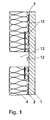
- FIG. 1 Section shown by a multilayer element according to the invention shows a thin cover plate 1 made of natural stone, on the underside of a CFRP fabric of small thickness executed as a planar reinforcement intermediate layer 2 is adhesively bonded by means of an epoxy resin.
- the thin cover plate 1 may also be made of glass, wood, metal or other stable material.
- the CFRP fabric has a high modulus of elasticity compared to the natural stone slab; The tensile and compressive strength of the CFRP fabric is significantly greater than the compressive strength of natural stone.
- a pressure-resistant foam layer made of expanded polypropylene is adhesively bonded to the surface.
- the illustrated multilayer construction achieves a high flexural strength at low weight of the multilayered element.
- An expedient embodiment provides that the reinforcement is arranged within the lightweight material layer 4.
- the introduction of reinforcing elements can advantageously also be carried out by incorporating slots or grooves for receiving strip-shaped reinforcements 2 into the lightweight material layer 4.
- the grooves can, for example, in prefabricated Lightweight panels are already incorporated before the connection with the thin cover plate 1, to subsequently glued strip-shaped reinforcements in these grooves. Slits can be achieved, for example, by gluing the lightweight panels in smaller parts with appropriate distances between them with the cover plate. 1 At all four edges of the lightweight material layer 4 of the square floor element grooves 3 are arranged, which serve to receive connecting strips 9.
- the floor elements may have edge lengths of 200 to 2200 mm, preferably squares with an edge length of 300 to 500 mm and a thickness of 10 to 40 mm are used.
- the grooves 3 are shorter than the edges of the plates, so that the lightweight material layer 4 terminates flush with the cover plate 1 at the corners.
- the grooves can be arranged directly at the interface of the cover plate 1 and the lightweight material layer 4 or also in the lightweight material layer 4 and be spaced from the interface.
- grooves 12 At the top and bottom of the lightweight material layer 4 intersecting grooves 12 are arranged, in which evaporate on the underside of the cover plates 1 forming condensation moisture and can be removed. By means of the grooves 12, it is also possible to guide atmospheric moisture arising from the substrate or water penetrating from the cover plate 1 to the edge of the floor surface.
- the grooves may lie parallel and congruent one above the other in the upper and lower sides or may also be offset from one another.
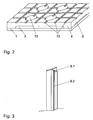
- FIG. 2 an isometric view of the element according to the invention from below, shown recesses 13, preferably the Touch grooves 12, in particular at the intersections of the grooves, warm air can be guided by a heat source located below the layer of lightweight material to the cover plate 1. Through the grooves 12, the hot air is supplied to a larger area and thus heats the cover plate 1. In this embodiment, it is expedient to use a foam of increased density, so that the lower carrying capacity is compensated by the recesses.
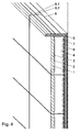
- a connection bar 9 is in FIG. 3 shown.
- the connecting bar 9 has at least two horizontal legs 9.1.
- the in the FIG. 2 illustrated embodiment is similar to a T-profile and has two horizontal legs 9.1 and an additional vertical leg 9.2.
- the thickness of the horizontal leg 9.1 is slightly smaller than the width of the grooves 3; in the longitudinal direction of the profile 9.1 profiling are arranged on the horizontal legs, which serve to clamp the horizontal leg 9.1 safely in the grooves 3 and so serve the compound adjacent arranged multilayer cover plates.
- the vertical leg 9.2 serves to maintain a defined butt joint width between the multilayer plates.
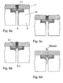
- FIG. 4 shows an isometric cutout of an overall arrangement of a floor with a plurality of interconnected by connecting strips 9 multi-layer elements.
- the multilayer elements are laid on a flat lower layer; the lower layer consists of a lower film 8 with a quick-setting floating screed 7 poured over it. Above the screed 7, an upper film 6 is arranged.
- the lateral boundary of the floor is an L-shaped, arranged metallic angle profile 5, the horizontal leg is covered with the flow screed 7. Through this overlap, the angle section 5 is fixed in the lower layer.
- On the side facing the floor of the vertical leg of the angle section 5 is provided with a compressible sealing strip, which prevents the escape of mortar from the frame.
- FIG. 5 explains a detail of a joint, in which there are additional fastening rails 10 in the side surfaces of the lightweight material layer 10, which have a groove into which the horizontal leg 9.1 of the connecting strips 9 engage.
- the horizontal leg 9.1 are formed by a slit elastic and provided at the lower ends with thickenings, which engage in corresponding, attached to the inner surfaces of the mounting rails undercuts and allow a positive but releasable connection, and so a safe and gap-free arrangement adjacent elements allows.
- the vertical leg 9.2 are provided on its upper side with a colored edge strip 11 made of an elastic plastic, which fulfills both decorative tasks and improves the seal. The surface of the edge strip 11 can be next to the in FIG.
- connection bar 9 consists only of the two horizontal legs 9.2, which are provided with openings. This makes it possible to dissipate water from the surfaces of the elements, which thereby run into the gap between adjacent elements and can be derived through the connecting bar 9 therethrough.
- the grooves 3 are generated by recesses in the lightweight material layer 4, so that the additional, expensive use of mounting rails 10 is eliminated.
- dechtstoff für 4 and the cover plate 1 further layers may be arranged, for example, a metal layer to distribute the heat of a heater even more evenly.
- the grooves 12 may be either continuous, so that, for example, form long channels in the association of several floor elements, or they may end within the surface of the lightweight material layer 4, so that they do not break the edge thereof or the grooves 3.
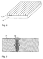
- cover plates are strip-shaped.
- a plurality of parallel strip-shaped individual elements 1.1 are glued on the carrier element consisting of a lightweight material layer 4.
- a lightweight material layer 4 Especially suitable for this are strips of wood.
- the individual elements can also be formed in any other forms, the attachment can be done both by gluing, as well as by means of screws, nails or other suitable connection options.
- the strip-shaped individual elements 1.1 are fastened on a carrier element that can be in the form of a plate or a frame.
- connection of adjacent elements takes place by means of connecting elements which respectively engage in grooves which are located on vertical surfaces of adjacent elements.
- the connecting elements can be arranged between the individual elements 1.1 and / or at between adjacent carrier elements.
- the connection is effected by means of a detent.
- the strip-shaped individual elements 1.1 are located on a carrier element, which consists of a pressure-resistant lightweight material layer.
- the sealing profile 1.2 consists in the case shown of a rubber strip which is reinforced for the purpose of better mountability with a plastic core and has two lateral beads which engage in grooves which are incorporated into the vertical surfaces of the wooden strips. At the upwardly projecting portion of the sealing profile 1.2 a thickening is mounted, which are in the example shown in chamfers of the individual elements 1.1. To achieve a high level of slip resistance, the sealing profile 1.2 can also protrude above the wooden strips. Of course, the sealing profile 1.2 can also be made of other materials, such as plastic or metal.
- FIG. 8 explains an embodiment in which an intermediate layer 2 of fleece is glued to the lightweight material layer 4. This layer facilitates the bonding of cover plates 1.
Landscapes
- Engineering & Computer Science (AREA)
- Architecture (AREA)
- Civil Engineering (AREA)
- Structural Engineering (AREA)
- Chemical & Material Sciences (AREA)
- Ceramic Engineering (AREA)
- Floor Finish (AREA)
Claims (2)
- Elément de surface stratifié pour planchers, comportant une dalle de couverture (1) mince, résistante à la pression et à l'usure, qui forme la face supérieure de l'élément stratifié, et où un élément support résistant à la pression est disposé contre la face inférieure de la dalle de couverture (1) mince, résistante à la pression et à l'usure et fixé à celle-ci par collage, des rainures (3) étant ménagées dans des surfaces de bord verticales et des baguettes de raccordement (9) étant applicables dans les rainures (3) pour l'assemblage d'éléments stratifiés adjacents, caractérisé- en ce que l'élément support est composé d'une couche de matériau léger (4) en polypropylène expansé, résistante à la pression, et- en ce que les rainures (3) sont ménagées dans la couche de matériau léger (4) et présentent une longueur inférieure à la longueur de bord correspondante de l'élément support, ledit élément support et la dalle de couverture (1) à l'extérieur des rainures (3) affleurant l'un contre l'autre à l'exception des inégalités de surface.
- Elément de surface selon la revendication 1, caractérisé en ce que l'élément support présente des gorges (12) sur sa face inférieure et/ou sa face supérieure.
Applications Claiming Priority (6)
| Application Number | Priority Date | Filing Date | Title |
|---|---|---|---|
| WOPCT/DE03/03357 | 2003-09-18 | ||
| DE20314548 | 2003-09-18 | ||
| DE20314548U | 2003-09-18 | ||
| PCT/DE2003/003357 WO2005035906A1 (fr) | 2003-09-18 | 2003-09-18 | Element de plancher chauffant pourvu d'une couche superficielle |
| DE202004013987U | 2004-09-06 | ||
| DE202004013987U DE202004013987U1 (de) | 2004-09-06 | 2004-09-06 | Beheizbares Fußbodenelement mit Oberflächenschicht |
Publications (3)
| Publication Number | Publication Date |
|---|---|
| EP1516976A2 EP1516976A2 (fr) | 2005-03-23 |
| EP1516976A3 EP1516976A3 (fr) | 2006-07-05 |
| EP1516976B1 true EP1516976B1 (fr) | 2010-01-20 |
Family
ID=34195908
Family Applications (1)
| Application Number | Title | Priority Date | Filing Date |
|---|---|---|---|
| EP04021868A Expired - Lifetime EP1516976B1 (fr) | 2003-09-18 | 2004-09-15 | Elément multicouche de revêtement de sol avec des rainures pour des profilés d'assemblage |
Country Status (3)
| Country | Link |
|---|---|
| EP (1) | EP1516976B1 (fr) |
| AT (1) | ATE455911T1 (fr) |
| DE (1) | DE502004010666D1 (fr) |
Families Citing this family (1)
| Publication number | Priority date | Publication date | Assignee | Title |
|---|---|---|---|---|
| WO2019137824A1 (fr) * | 2018-01-15 | 2019-07-18 | Josef Stengel | Système de fabrication d'un revêtement mural ou d'un revêtement de sol |
Family Cites Families (7)
| Publication number | Priority date | Publication date | Assignee | Title |
|---|---|---|---|---|
| NL7316287A (nl) * | 1973-12-07 | 1975-05-30 | Mallinson & Mott Ltd | Bouwpaneel en de vervaardiging van een bouwpaneel. |
| JPS62264253A (ja) * | 1986-05-08 | 1987-11-17 | ジヤパンインテリアプランニング株式会社 | タイル材、及びその製造法 |
| AT396232B (de) * | 1988-12-07 | 1993-07-26 | Wolfgang Lehner | Verfahren zum beschichten von moebeln, waenden und fussboeden mit duennen natur- oder kunststeinschichten |
| JPH11324291A (ja) * | 1998-05-08 | 1999-11-26 | Kanegafuchi Chem Ind Co Ltd | 建築用遮音床構造 |
| DE10201905B4 (de) * | 2001-03-26 | 2004-07-08 | Peter Kellner | Fußboden aus einzelnen Elementen |
| DE10133813A1 (de) * | 2001-05-20 | 2005-01-13 | Fagerdala Deutschland Gmbh | Verfahren zur Herstellung von Teilen, teilweise bestehend aus Kunststoffschaum |
| WO2005035906A1 (fr) * | 2003-09-18 | 2005-04-21 | Peter Kellner | Element de plancher chauffant pourvu d'une couche superficielle |
-
2004
- 2004-09-15 AT AT04021868T patent/ATE455911T1/de not_active IP Right Cessation
- 2004-09-15 EP EP04021868A patent/EP1516976B1/fr not_active Expired - Lifetime
- 2004-09-15 DE DE502004010666T patent/DE502004010666D1/de not_active Expired - Lifetime
Also Published As
| Publication number | Publication date |
|---|---|
| EP1516976A3 (fr) | 2006-07-05 |
| ATE455911T1 (de) | 2010-02-15 |
| DE502004010666D1 (de) | 2010-03-11 |
| EP1516976A2 (fr) | 2005-03-23 |
Similar Documents
| Publication | Publication Date | Title |
|---|---|---|
| EP1911905B1 (fr) | Système de construction multicouche pour revêtements de sol pour chauffages par le sol | |
| DE102008044803B4 (de) | Fußbodensystem | |
| EP1490565A1 (fr) | Systeme de pose de dalles | |
| EP1373658B1 (fr) | Elément de sol multicouche | |
| DE3317731A1 (de) | Bodenplatte | |
| DE19828607A1 (de) | Verfahren zum Verstärken von Stahl- und Spannbetonbauteilen | |
| DE20107338U1 (de) | Flexibles Bodenbelagsträgersystem | |
| WO2004018798A2 (fr) | Plancher constitue d'elements individuels | |
| WO2005035906A1 (fr) | Element de plancher chauffant pourvu d'une couche superficielle | |
| DE102006035135B4 (de) | Noppenbauelement | |
| DE10249493B4 (de) | Bodenaufbausystem für Keramik-, Fliesen- und Plattenbeläge | |
| DE202009003690U1 (de) | Entkopplungsmatte | |
| WO2004042166A1 (fr) | Panneau plat pour revetements de sols, de murs et de plafonds, pour des parois de separation et des meubles | |
| DE20215223U1 (de) | Fußboden aus einzelnen Elementen | |
| EP1516976A2 (fr) | Elément multicouche de revêtement de sol avec des rainures pour des profilés d'assemblage | |
| DE202004015283U1 (de) | Fußbodenelement mit Oberflächenschicht | |
| DE3925742C2 (de) | Sporthallenboden | |
| DE202004013987U1 (de) | Beheizbares Fußbodenelement mit Oberflächenschicht | |
| DE10061477B4 (de) | Vorgefertigtes, großformatiges plattenförmiges Bauelement | |
| DE202014104792U1 (de) | Trägeranordnung für elektrische Heizkabel einer Flächenheizung | |
| EP1630321A2 (fr) | Tapis de pose pour carreaux et procédé pour la pose de carreaux | |
| EP1526225A2 (fr) | Système d'armature pour revêtements rigides d'une grande portance sur support plan, en particulier pour revêtements faits de panneaux ou carrelages | |
| DE4343372A1 (de) | Massivholzdielenboden und Arbeitsverfahren zu seiner Verlegung | |
| DE102004022446B4 (de) | Vorgefertigtes, großformatiges, plattenförmiges Bauelement | |
| DE102006053706B4 (de) | Bodenaufbausystem für aufgestelzte Bodenbeläge sowie Verfahren zur Montage des Systems |
Legal Events
| Date | Code | Title | Description |
|---|---|---|---|
| PUAI | Public reference made under article 153(3) epc to a published international application that has entered the european phase |
Free format text: ORIGINAL CODE: 0009012 |
|
| AK | Designated contracting states |
Kind code of ref document: A2 Designated state(s): AT BE BG CH CY CZ DE DK EE ES FI FR GB GR HU IE IT LI LU MC NL PL PT RO SE SI SK TR |
|
| AX | Request for extension of the european patent |
Extension state: AL HR LT LV MK |
|
| 17P | Request for examination filed |
Effective date: 20050526 |
|
| PUAL | Search report despatched |
Free format text: ORIGINAL CODE: 0009013 |
|
| AK | Designated contracting states |
Kind code of ref document: A3 Designated state(s): AT BE BG CH CY CZ DE DK EE ES FI FR GB GR HU IE IT LI LU MC NL PL PT RO SE SI SK TR |
|
| AX | Request for extension of the european patent |
Extension state: AL HR LT LV MK |
|
| 17Q | First examination report despatched |
Effective date: 20061123 |
|
| AKX | Designation fees paid |
Designated state(s): AT BE BG CH CY CZ DE DK EE ES FI FR GB GR HU IE IT LI LU MC NL PL PT RO SE SI SK TR |
|
| 17Q | First examination report despatched |
Effective date: 20061123 |
|
| GRAP | Despatch of communication of intention to grant a patent |
Free format text: ORIGINAL CODE: EPIDOSNIGR1 |
|
| GRAS | Grant fee paid |
Free format text: ORIGINAL CODE: EPIDOSNIGR3 |
|
| GRAA | (expected) grant |
Free format text: ORIGINAL CODE: 0009210 |
|
| AK | Designated contracting states |
Kind code of ref document: B1 Designated state(s): AT BE BG CH CY CZ DE DK EE ES FI FR GB GR HU IE IT LI LU MC NL PL PT RO SE SI SK TR |
|
| REG | Reference to a national code |
Ref country code: GB Ref legal event code: FG4D Free format text: NOT ENGLISH |
|
| REG | Reference to a national code |
Ref country code: CH Ref legal event code: EP |
|
| REG | Reference to a national code |
Ref country code: IE Ref legal event code: FG4D |
|
| REF | Corresponds to: |
Ref document number: 502004010666 Country of ref document: DE Date of ref document: 20100311 Kind code of ref document: P |
|
| REG | Reference to a national code |
Ref country code: NL Ref legal event code: VDEP Effective date: 20100120 |
|
| PG25 | Lapsed in a contracting state [announced via postgrant information from national office to epo] |
Ref country code: NL Free format text: LAPSE BECAUSE OF FAILURE TO SUBMIT A TRANSLATION OF THE DESCRIPTION OR TO PAY THE FEE WITHIN THE PRESCRIBED TIME-LIMIT Effective date: 20100120 Ref country code: ES Free format text: LAPSE BECAUSE OF FAILURE TO SUBMIT A TRANSLATION OF THE DESCRIPTION OR TO PAY THE FEE WITHIN THE PRESCRIBED TIME-LIMIT Effective date: 20100501 Ref country code: PT Free format text: LAPSE BECAUSE OF FAILURE TO SUBMIT A TRANSLATION OF THE DESCRIPTION OR TO PAY THE FEE WITHIN THE PRESCRIBED TIME-LIMIT Effective date: 20100520 |
|
| REG | Reference to a national code |
Ref country code: IE Ref legal event code: FD4D |
|
| PG25 | Lapsed in a contracting state [announced via postgrant information from national office to epo] |
Ref country code: PL Free format text: LAPSE BECAUSE OF FAILURE TO SUBMIT A TRANSLATION OF THE DESCRIPTION OR TO PAY THE FEE WITHIN THE PRESCRIBED TIME-LIMIT Effective date: 20100120 Ref country code: SI Free format text: LAPSE BECAUSE OF FAILURE TO SUBMIT A TRANSLATION OF THE DESCRIPTION OR TO PAY THE FEE WITHIN THE PRESCRIBED TIME-LIMIT Effective date: 20100120 Ref country code: FI Free format text: LAPSE BECAUSE OF FAILURE TO SUBMIT A TRANSLATION OF THE DESCRIPTION OR TO PAY THE FEE WITHIN THE PRESCRIBED TIME-LIMIT Effective date: 20100120 |
|
| PG25 | Lapsed in a contracting state [announced via postgrant information from national office to epo] |
Ref country code: IE Free format text: LAPSE BECAUSE OF FAILURE TO SUBMIT A TRANSLATION OF THE DESCRIPTION OR TO PAY THE FEE WITHIN THE PRESCRIBED TIME-LIMIT Effective date: 20100120 Ref country code: GR Free format text: LAPSE BECAUSE OF FAILURE TO SUBMIT A TRANSLATION OF THE DESCRIPTION OR TO PAY THE FEE WITHIN THE PRESCRIBED TIME-LIMIT Effective date: 20100421 Ref country code: CY Free format text: LAPSE BECAUSE OF FAILURE TO SUBMIT A TRANSLATION OF THE DESCRIPTION OR TO PAY THE FEE WITHIN THE PRESCRIBED TIME-LIMIT Effective date: 20100120 Ref country code: EE Free format text: LAPSE BECAUSE OF FAILURE TO SUBMIT A TRANSLATION OF THE DESCRIPTION OR TO PAY THE FEE WITHIN THE PRESCRIBED TIME-LIMIT Effective date: 20100120 Ref country code: SE Free format text: LAPSE BECAUSE OF FAILURE TO SUBMIT A TRANSLATION OF THE DESCRIPTION OR TO PAY THE FEE WITHIN THE PRESCRIBED TIME-LIMIT Effective date: 20100120 Ref country code: RO Free format text: LAPSE BECAUSE OF FAILURE TO SUBMIT A TRANSLATION OF THE DESCRIPTION OR TO PAY THE FEE WITHIN THE PRESCRIBED TIME-LIMIT Effective date: 20100120 |
|
| PLBE | No opposition filed within time limit |
Free format text: ORIGINAL CODE: 0009261 |
|
| STAA | Information on the status of an ep patent application or granted ep patent |
Free format text: STATUS: NO OPPOSITION FILED WITHIN TIME LIMIT |
|
| PG25 | Lapsed in a contracting state [announced via postgrant information from national office to epo] |
Ref country code: CZ Free format text: LAPSE BECAUSE OF FAILURE TO SUBMIT A TRANSLATION OF THE DESCRIPTION OR TO PAY THE FEE WITHIN THE PRESCRIBED TIME-LIMIT Effective date: 20100120 Ref country code: SK Free format text: LAPSE BECAUSE OF FAILURE TO SUBMIT A TRANSLATION OF THE DESCRIPTION OR TO PAY THE FEE WITHIN THE PRESCRIBED TIME-LIMIT Effective date: 20100120 Ref country code: BG Free format text: LAPSE BECAUSE OF FAILURE TO SUBMIT A TRANSLATION OF THE DESCRIPTION OR TO PAY THE FEE WITHIN THE PRESCRIBED TIME-LIMIT Effective date: 20100420 |
|
| PGFP | Annual fee paid to national office [announced via postgrant information from national office to epo] |
Ref country code: FR Payment date: 20100930 Year of fee payment: 7 |
|
| 26N | No opposition filed |
Effective date: 20101021 |
|
| PGFP | Annual fee paid to national office [announced via postgrant information from national office to epo] |
Ref country code: GB Payment date: 20100924 Year of fee payment: 7 |
|
| PG25 | Lapsed in a contracting state [announced via postgrant information from national office to epo] |
Ref country code: DK Free format text: LAPSE BECAUSE OF FAILURE TO SUBMIT A TRANSLATION OF THE DESCRIPTION OR TO PAY THE FEE WITHIN THE PRESCRIBED TIME-LIMIT Effective date: 20100120 |
|
| PGFP | Annual fee paid to national office [announced via postgrant information from national office to epo] |
Ref country code: DE Payment date: 20101125 Year of fee payment: 7 |
|
| BERE | Be: lapsed |
Owner name: KELLNER, PETER Effective date: 20100930 |
|
| PG25 | Lapsed in a contracting state [announced via postgrant information from national office to epo] |
Ref country code: IT Free format text: LAPSE BECAUSE OF FAILURE TO SUBMIT A TRANSLATION OF THE DESCRIPTION OR TO PAY THE FEE WITHIN THE PRESCRIBED TIME-LIMIT Effective date: 20100120 |
|
| PG25 | Lapsed in a contracting state [announced via postgrant information from national office to epo] |
Ref country code: MC Free format text: LAPSE BECAUSE OF NON-PAYMENT OF DUE FEES Effective date: 20100930 |
|
| REG | Reference to a national code |
Ref country code: CH Ref legal event code: PL |
|
| PG25 | Lapsed in a contracting state [announced via postgrant information from national office to epo] |
Ref country code: LI Free format text: LAPSE BECAUSE OF NON-PAYMENT OF DUE FEES Effective date: 20100930 Ref country code: CH Free format text: LAPSE BECAUSE OF NON-PAYMENT OF DUE FEES Effective date: 20100930 Ref country code: BE Free format text: LAPSE BECAUSE OF NON-PAYMENT OF DUE FEES Effective date: 20100930 |
|
| PG25 | Lapsed in a contracting state [announced via postgrant information from national office to epo] |
Ref country code: AT Free format text: LAPSE BECAUSE OF NON-PAYMENT OF DUE FEES Effective date: 20100915 |
|
| GBPC | Gb: european patent ceased through non-payment of renewal fee |
Effective date: 20110915 |
|
| REG | Reference to a national code |
Ref country code: FR Ref legal event code: ST Effective date: 20120531 |
|
| REG | Reference to a national code |
Ref country code: DE Ref legal event code: R119 Ref document number: 502004010666 Country of ref document: DE Effective date: 20120403 |
|
| PG25 | Lapsed in a contracting state [announced via postgrant information from national office to epo] |
Ref country code: DE Free format text: LAPSE BECAUSE OF NON-PAYMENT OF DUE FEES Effective date: 20120403 |
|
| PG25 | Lapsed in a contracting state [announced via postgrant information from national office to epo] |
Ref country code: FR Free format text: LAPSE BECAUSE OF NON-PAYMENT OF DUE FEES Effective date: 20110930 Ref country code: GB Free format text: LAPSE BECAUSE OF NON-PAYMENT OF DUE FEES Effective date: 20110915 |
|
| PG25 | Lapsed in a contracting state [announced via postgrant information from national office to epo] |
Ref country code: LU Free format text: LAPSE BECAUSE OF NON-PAYMENT OF DUE FEES Effective date: 20100915 Ref country code: HU Free format text: LAPSE BECAUSE OF FAILURE TO SUBMIT A TRANSLATION OF THE DESCRIPTION OR TO PAY THE FEE WITHIN THE PRESCRIBED TIME-LIMIT Effective date: 20100721 |
|
| PG25 | Lapsed in a contracting state [announced via postgrant information from national office to epo] |
Ref country code: TR Free format text: LAPSE BECAUSE OF FAILURE TO SUBMIT A TRANSLATION OF THE DESCRIPTION OR TO PAY THE FEE WITHIN THE PRESCRIBED TIME-LIMIT Effective date: 20100120 |