EP2090867A1 - Navigationssystem, tragbares endgerät und verfahren zur anzeige eines peripheriebildes - Google Patents
Navigationssystem, tragbares endgerät und verfahren zur anzeige eines peripheriebildes Download PDFInfo
- Publication number
- EP2090867A1 EP2090867A1 EP06834025A EP06834025A EP2090867A1 EP 2090867 A1 EP2090867 A1 EP 2090867A1 EP 06834025 A EP06834025 A EP 06834025A EP 06834025 A EP06834025 A EP 06834025A EP 2090867 A1 EP2090867 A1 EP 2090867A1
- Authority
- EP
- European Patent Office
- Prior art keywords
- imaging means
- display
- image
- displayed
- peripheral image
- Prior art date
- Legal status (The legal status is an assumption and is not a legal conclusion. Google has not performed a legal analysis and makes no representation as to the accuracy of the status listed.)
- Withdrawn
Links
Images






Classifications
-
- G—PHYSICS
- G01—MEASURING; TESTING
- G01C—MEASURING DISTANCES, LEVELS OR BEARINGS; SURVEYING; NAVIGATION; GYROSCOPIC INSTRUMENTS; PHOTOGRAMMETRY OR VIDEOGRAMMETRY
- G01C21/00—Navigation; Navigational instruments not provided for in groups G01C1/00 - G01C19/00
- G01C21/26—Navigation; Navigational instruments not provided for in groups G01C1/00 - G01C19/00 specially adapted for navigation in a road network
-
- G—PHYSICS
- G08—SIGNALLING
- G08G—TRAFFIC CONTROL SYSTEMS
- G08G1/00—Traffic control systems for road vehicles
- G08G1/005—Traffic control systems for road vehicles including pedestrian guidance indicator
-
- G—PHYSICS
- G01—MEASURING; TESTING
- G01C—MEASURING DISTANCES, LEVELS OR BEARINGS; SURVEYING; NAVIGATION; GYROSCOPIC INSTRUMENTS; PHOTOGRAMMETRY OR VIDEOGRAMMETRY
- G01C21/00—Navigation; Navigational instruments not provided for in groups G01C1/00 - G01C19/00
- G01C21/20—Instruments for performing navigational calculations
-
- G—PHYSICS
- G01—MEASURING; TESTING
- G01C—MEASURING DISTANCES, LEVELS OR BEARINGS; SURVEYING; NAVIGATION; GYROSCOPIC INSTRUMENTS; PHOTOGRAMMETRY OR VIDEOGRAMMETRY
- G01C21/00—Navigation; Navigational instruments not provided for in groups G01C1/00 - G01C19/00
- G01C21/26—Navigation; Navigational instruments not provided for in groups G01C1/00 - G01C19/00 specially adapted for navigation in a road network
- G01C21/34—Route searching; Route guidance
-
- G—PHYSICS
- G01—MEASURING; TESTING
- G01C—MEASURING DISTANCES, LEVELS OR BEARINGS; SURVEYING; NAVIGATION; GYROSCOPIC INSTRUMENTS; PHOTOGRAMMETRY OR VIDEOGRAMMETRY
- G01C21/00—Navigation; Navigational instruments not provided for in groups G01C1/00 - G01C19/00
- G01C21/26—Navigation; Navigational instruments not provided for in groups G01C1/00 - G01C19/00 specially adapted for navigation in a road network
- G01C21/34—Route searching; Route guidance
- G01C21/36—Input/output arrangements for on-board computers
- G01C21/3626—Details of the output of route guidance instructions
- G01C21/3647—Guidance involving output of stored or live camera images or video streams
-
- G—PHYSICS
- G08—SIGNALLING
- G08G—TRAFFIC CONTROL SYSTEMS
- G08G1/00—Traffic control systems for road vehicles
- G08G1/09—Arrangements for giving variable traffic instructions
- G08G1/0962—Arrangements for giving variable traffic instructions having an indicator mounted inside the vehicle, e.g. giving voice messages
- G08G1/0968—Systems involving transmission of navigation instructions to the vehicle
- G08G1/096805—Systems involving transmission of navigation instructions to the vehicle where the transmitted instructions are used to compute a route
- G08G1/096811—Systems involving transmission of navigation instructions to the vehicle where the transmitted instructions are used to compute a route where the route is computed offboard
- G08G1/096816—Systems involving transmission of navigation instructions to the vehicle where the transmitted instructions are used to compute a route where the route is computed offboard where the complete route is transmitted to the vehicle at once
-
- G—PHYSICS
- G08—SIGNALLING
- G08G—TRAFFIC CONTROL SYSTEMS
- G08G1/00—Traffic control systems for road vehicles
- G08G1/09—Arrangements for giving variable traffic instructions
- G08G1/0962—Arrangements for giving variable traffic instructions having an indicator mounted inside the vehicle, e.g. giving voice messages
- G08G1/0968—Systems involving transmission of navigation instructions to the vehicle
- G08G1/096855—Systems involving transmission of navigation instructions to the vehicle where the output is provided in a suitable form to the driver
- G08G1/096861—Systems involving transmission of navigation instructions to the vehicle where the output is provided in a suitable form to the driver where the immediate route instructions are output to the driver, e.g. arrow signs for next turn
-
- G—PHYSICS
- G08—SIGNALLING
- G08G—TRAFFIC CONTROL SYSTEMS
- G08G1/00—Traffic control systems for road vehicles
- G08G1/09—Arrangements for giving variable traffic instructions
- G08G1/0962—Arrangements for giving variable traffic instructions having an indicator mounted inside the vehicle, e.g. giving voice messages
- G08G1/0968—Systems involving transmission of navigation instructions to the vehicle
- G08G1/096877—Systems involving transmission of navigation instructions to the vehicle where the input to the navigation device is provided by a suitable I/O arrangement
- G08G1/096883—Systems involving transmission of navigation instructions to the vehicle where the input to the navigation device is provided by a suitable I/O arrangement where input information is obtained using a mobile device, e.g. a mobile phone, a PDA
Definitions
- the present invention relates to a communication-type pedestrian navigation system for searching for a guidance route from a start point up to a destination, and using image information displayed on display means of a portable terminal device for guidance along the route.
- the present invention relates in particular to a communication-type pedestrian navigation system for imaging a peripheral scene in intersections or other such locations using imaging means of the portable terminal device; for displaying the captured image on display means as a peripheral image; and, in a case where the portable terminal device is held in a position suitable for the user to view a display screen thereof when a route guide image, a guidance image in a direction of advance, or another image is to be displayed on top of the displayed peripheral image, for displaying a horizontal direction of the peripheral image on the display screen even if a direction of an optical axis of the imaging means is directed downward from a horizontal line.
- a traveler when traveling to a destination in an unfamiliar place, a traveler followed an atlas or the like and arrived at the destination by identifying a transport facility, a road, a landmark, or an address shown in the map.
- a navigation system hereinafter referred to as a car navigation system
- a traveler reaches a destination while receiving guidance displayed on a monitor screen or voice guidance (navigation information) from the navigation system by activating the car navigation system and inputting the destination.
- the car navigation system described above uses a GPS (Global Positioning System) in which GPS signals transmitted from a plurality of GPS satellites orbiting the earth are received by a GPS antenna, and a position is determined by analyzing satellite positions, time information, and the like that are included in the GPS signals. At least four or more of the plurality of GPS satellites are needed to determine a position.
- the accuracy of independent positioning in a GPS in general is a little over 10 m, but the accuracy is enhanced to 5 m or less through the use of a DGPS (Differential GPS).
- DGPS Different GPS
- a trend in all models of so-called third-generation mobile telephones is the installation of GPS receivers that are currently installed only in some mobile telephones.
- a navigation service is one of these services, and a communication-type navigation system has been implemented for providing route guidance from a current position to a destination to not only the driver of an automobile, but also the user of a mobile telephone.
- Patent Document 1 Japanese Laid-open Patent Application No. 2001-165681
- information relating to the departure point and the destination is transmitted from a mobile navigation terminal to an information delivery server, the information delivery server searches a route that matches search conditions from road network or transportation network data, and guidance is provided.
- the search conditions include the means of travel from the departure point to the destination, examples of which include walking, an automobile, a railroad, a combination of railroad and walking, and the like.
- the route search is performed using this factor as one search condition.
- the information delivery server is provided with a database of cost information (distance or required time) for all links, wherein the links are routes that connect nodes, and nodes are the positions of junctions and turns in roads (routes) in the map data.
- the information delivery server can guide the mobile navigation terminal along the shortest route by referring to the database, sequentially searching the links that lead from the departure point node to the destination node, and creating a guide route by tracing nodes and links for which the cost information of the link indicates the smallest cost.
- a technique known as a label setting algorithm or a Dijkstra algorithm is used as the technique for performing this type of route search. In Patent Document 1 mentioned above, a route search method that uses this Dijkstra algorithm is also disclosed.
- the map information or guide route information displayed by the terminal device is downloaded from a route search server or other server device connected to the terminal device via a network.
- the terminal device to which the map information or guide route is delivered from the route search server or other information delivery server is provided with a liquid crystal display device or other display means, the map and guide route are displayed in the display means as well as the current position (current position of the terminal device) of the walker or automobile on the guide route, and the walker or automobile is guided to the destination.
- the map displayed in the display means is typically a plan view, i.e., a two-dimensional map display, but methods have been proposed for displaying a planar aerial map that brings a sense of perspective to the display image, or an aerial map in which buildings are simulated in three dimensions in order to make landmarks or buildings easier to recognize, or for displaying roads or buildings as three-dimensional polygon images by a Z buffer method.
- Patent Document 2 Japanese Laid-open Patent Application No. 2001-27535 discloses a map display device in which buildings or roads are displayed in three dimensions.
- shading is added to an image of the route guide line on an image of a road to create a three-dimensional map display.
- the overlapped portion and the non-overlapped portion of the route guide line are displayed in different colors.
- the display color of the route guide line and the display color of buildings are drawn by a semi-transparency method of setting mutually different colors in the pixel units in VRAM (video RAM), and the relative positioning of buildings and the route guide line is clarified to enhance the visibility of the route guide line.
- building shape data and height information are stored in the map data in the map display device disclosed in Patent Document 2, and multi-level crossings and other road shape data are also stored.
- buildings or multi-level road crossings are drawn in three dimensions in a drawing unit, and when the vehicle arrives at a position for which route guidance is to be provided, the desired image is drawn in the drawing unit, a predetermined sound is outputted by a voice output unit, and the user is guided to the destination.
- a map is generally displayed in three dimensions using polygon data in the following manner. Specifically, the surfaces that form each building to be displayed in the map are prepared as polygon data, and the building polygon data are transmitted together with the map data to the map display device.
- the map display device displays the map and displays each building positions on the map in three dimensions using the polygon data.
- textures are applied to the surfaces of the buildings and displayed in order to more realistically display the buildings.
- the textures are data for showing patterns on the surfaces of the buildings, and include the shapes of windows in the buildings, wall designs, and the like.
- Patent Document 3 Japanese Laid-open Patent Application No. 2000-259861 discloses a texture mapping device whereby textures are applied to polygon data and drawn.
- the invention disclosed in Patent Document 3 accurately and efficiently applies textures to polygons and facilitates subsequent editing.
- This texture mapping device designates square polygons P1 through P4 arranged in M lines and N columns on a wire frame, and textures applied thereto.
- the textures to be applied are divided according to the ratio of the edge lengths Lp1 through Lp12 of the designated plurality of polygons P1 through P4.
- a configuration is adopted in which the orientation of the polygons is taken into account to apply the divided textures to the corresponding polygons.
- the polygon data indicating the surfaces of the buildings, and the texture data to be applied to the surfaces have a one-to-one correspondence
- the texture data are accumulated in the server database along with the polygon data
- the polygon data and texture data of the buildings to be displayed on the map are transmitted to the map display device together with a predetermined range of map data.
- map data for three-dimensional display separate from the plan-view map data are necessary in order to display the map in three dimensions.
- Three-dimensional map data include more data than plan-view map data, and a large-capacity storage device is needed as the storage device for storing the map data.
- the communication load between the terminal device and the route search server is also large, and there are also long communication times. Therefore, various problems arise such as the need for processing performance in the route search server sufficient to provide service to numerous terminal devices.
- Patent Document 4 Japanese Laid-open Patent Application No. 2004-257979
- Patent Document 5 Japanese Laid-open Patent Application No. 2006-162442
- an image of a scene in the forward direction is captured using a CCD camera or other imaging means
- the captured peripheral image is displayed on a display screen
- a forward direction guidance image of a right turn or a left turn is displayed superimposed on the peripheral image
- the guide route is displayed in a car-mounted navigation device.
- the navigation device disclosed in Patent Document 4 is provided with imaging means for capturing an image of a scene in the direction of advance, and display means for displaying an image captured by the imaging means; and when a branch point on a route detected by route detection means and a current position detected by current position detection means are equal to or less than a predetermined distance from each other, an image for guiding the user in a recommended direction of travel at the branch point is superimposed on the image captured by the imaging means and displayed in the display means.
- a guide information specifying unit is provided with a guide information specifying unit for specifying a position on a map for presenting guide information, and the type of guide information presented; an obstacle detection unit for detecting the position and type of obstacles (pedestrians, vehicles, and the like) around the vehicle in which the device is used through the use of object recognition or the like; a display position determination unit for calculating a position that does not coincide with an obstacle detected in a display position of the guide information; and an image output unit for outputting guide information in a determined position within the windshield view of the vehicle, or a determined position within the frontal image display region; and the direction of travel along the route is superimposed and displayed on the actual scene viewed from the vehicle.
- Navigation systems for use by a walker also include the portable terminal device and navigation device disclosed in Patent Document 6 (Japanese Laid-open Patent Application No. 2005-241385 ) in which the route direction is superimposed and displayed on an image of the actual surroundings that is captured by a camera.
- the screen of the digital camera is demarcated based on the current position of the user (destination guidance device), destination direction coordinates that correspond to the destination are determined for the screen, and an instructional display with respect to the destination direction coordinates is superimposed on the captured camera image on the screen on the basis of a predetermined reference point (the middle of the lower edge of the screen).
- a map image or another image prepared in advance by a computer system is captured along with an image of the actual scene.
- Undesired contrasting objects are removed from the image of the actual scene and replaced by the images prepared by the computer system.
- the system produces an enlarged image from the image of the actual scene and the image created by the computer; therefore, the attitude of the imaging means is adjusted so that the vertical and horizontal directions of the enlarged image directly correspond to the vertical and horizontal directions of the scene, and the normal to the plane of the image is oriented in the direction heading from the user toward the actual scene.
- the invention according to Prior Application 1 relates to a communication-type pedestrian navigation system for searching for a guidance route from a start point up to a destination, and using image information displayed on display means to provide guidance along the route.
- the invention relates in particular to a pedestrian navigation system for imaging a peripheral scene in intersections or other such locations; displaying the captured image on display means as a peripheral image; and, in a case where the route image cannot be displayed on the peripheral image when a route guide image or a guidance image in a direction of advance is to be displayed on top of the displayed peripheral image, for providing guidance along an imaged direction within which the route image can be displayed.
- a mobile telephone equipped with imaging means is used as the terminal device.
- the system is configured so that, in a case where the user is to capture an image of the peripheral scene in an intersection or other such location, an optical axis of the camera is brought into alignment with the horizontal direction and the image is captured, as with the electro-optical viewing system disclosed in Patent Document 7 referenced above.
- the optical axis of the camera will typically be in a parallel positional relationship with respect to the axis of the direction perpendicular to the display screen. Therefore, the display means of the mobile telephone will be oriented in a direction that is at a right angle with respect to the horizontal direction; i.e., the normal, which is the optical axis of the imaging means.
- the optical axis of the imaging means will be directed downward from the horizontal direction, and a further problem will be presented in that the horizontal direction of the captured peripheral image will not be oriented in the direction perpendicular to the display screen, an unnatural image will be displayed.
- a navigation device comprising an optical system for displaying a captured image, wherein a direction of an optical axis of imaging means is substantially parallel to the normal to a display screen of display means and a live image (a peripheral image captured using the imaging means) is used, as long as a control is performed in regard to displaying the live image to be displayed on the display means such that a center of the optical axis of the imaging means is positioned below a center of the display screen, and the horizontal direction of the peripheral image is displayed on the display screen even if the direction of the optical axis of the imaging means is directed downward from a horizontal line.
- a first aspect of the invention of the present application is a navigation system comprising: a route search server provided with route search means for referencing network data for route searching, and searching a guide route from a departure point to a destination; and a portable terminal device having guidance information storage means for storing guide information that includes guide route data, GPS receiving means for determining a current position, imaging means, and display means for displaying a peripheral image captured by the imaging means and a guide route, or a guidance image in a direction of advance or an image showing a point of interest; the navigation system characterized in that :
- the display control means compares a pixel region of an imaging element that constitutes the imaging means with a normal pixel region for showing a map image on the display means, and sets a different pixel region, thereby controlling the position in which the peripheral image captured by the imaging means is displayed so that the center of the optical axis of the imaging means will be positioned lower than the center of the display screen, and displaying the horizontal direction of the peripheral image on the display screen even if the direction of the optical axis of the imaging means is directed downward from the horizontal line.
- the imaging means further to have an imaging means shift mechanism; and, in a case where the peripheral image is displayed, for the imaging means to be shifted upward using the imaging means shift mechanism.
- a second aspect of the invention of the present application is a portable terminal device connected via a network to a route search server provided with route search means for referencing network data for route searching, and searching a guide route from a departure point to a destination; the portable terminal device characterized in comprising guidance information storage means for storing guide information that includes guide route data; GPS receiving means for determining a current position; imaging means; display means for displaying a peripheral image captured by the imaging means and a guide route, or a guidance image in a direction of advance or an image showing a point of interest; and display control means for controlling a display of the peripheral image displayed by the display means; wherein the display control means controls a position in which the peripheral image captured by the imaging means is displayed so that a center of an optical axis of the imaging means will be positioned lower than a center of a display screen, and displays a horizontal direction of the peripheral image on the display screen even if a direction of the optical axis of the imaging means is directed downward from a horizontal line.
- the display control means compares a pixel region of an imaging element that constitutes the imaging means with a normal pixel region for showing a map image on the display means, and sets a different pixel region, thereby controlling the position in which the peripheral image captured by the imaging means is displayed so that the center of the optical axis of the imaging means will be positioned lower than the center of the display screen, and displaying the horizontal direction of the peripheral image on the display screen even if the direction of the optical axis of the imaging means is directed downward from the horizontal line.
- the imaging means further to have an imaging means shift mechanism; and, in a case where the peripheral image is to be displayed, for the imaging means to be shifted upward using the imaging means shift mechanism.
- a third aspect of the invention of the present application is a peripheral-image display method for using a navigation system comprising a route search server provided with route search means for referencing network data for route searching, and searching a guide route from a departure point to a destination; and a portable terminal device having guidance information storage means for storing guide information that includes guide route data, GPS receiving means for determining a current position, imaging means, and display means for displaying a peripheral image captured by the imaging means and a guide route, or a guidance image in a direction of advance or an image showing a point of interest;
- the peripheral-image display method characterized in comprising:
- the display control means compares a pixel region of an imaging element that constitutes the imaging means with a normal pixel region for showing a map image on the display means, and sets a different pixel region, thereby controlling the position in which the peripheral image captured by the imaging means is displayed so that the center of the optical axis of the imaging means will be positioned lower than the center of the display screen, and displaying the horizontal direction of the peripheral image on the display screen even if the direction of the optical axis of the imaging means is directed downward from the horizontal line.
- the imaging means further to have an imaging means shift mechanism; and, in a case where the peripheral image is to be displayed, for the imaging means to be shifted upward using the imaging means shift mechanism.
- a peripheral scene in an intersection or another such location is imaged using imaging means of a portable terminal device; the captured image is displayed as a peripheral image on a display screen; and, in a case where the portable terminal device is held at an attitude that is suitable for the user to view the display screen when a route guide image, a guidance image in a direction of advance, an icon image indicating a point of interest, or another image is to be displayed on top of the displayed peripheral image, for displaying a horizontal direction of the peripheral image on the display means even if a direction of an optical axis of the imaging means is directed downward from a horizontal line.
- the second aspect of the invention of the present application it is possible to provide a portable terminal device constituting the navigation system according to the first aspect of the invention of the present application.
- the third aspect of the invention of the present application it is possible to provide a peripheral image display method in which the navigation system according to the first aspect of the invention of the present application is used.
- FIG. 1 is a block diagram showing the structure of the navigation system according to an embodiment of the present invention.
- the navigation system 10 is provided with a route search server 30 and a portable terminal device 20 that are connected via the Internet or another network 12, as shown in FIG. 1 .
- the route search server 30 is provided with route search means 33, a map database 34 in which map data are accumulated, and a database for route search network 35 in which transportation network data are accumulated that are road network data or public transportation facility network data used for route searching.
- the route search server 30 is also provided with a control means 301, communication means 31, and guidance information editing means 32.
- the control means 301 is a microprocessor having RAM, ROM, and a processor (not shown), and controls the operation of each component through the use of a control program stored in the ROM.
- the communication means 31 is an interface for communicating with the portable terminal device 20 via the network 12.
- the route search server 30 references the database for route search network 35 and searches for a guide route that matches the route search conditions when there is a route search request including a current position, a destination, movement means (automobile, walking, a transportation facility, a combination of walking and a transportation facility, or the like) and other route search conditions from the portable terminal device 20.
- the guide route data obtained as a result of the route search are collected in guide information (data) for transmission to the portable terminal device 20 by the guidance information editing means 32, together with unit map data (map data divided into areas of predetermined size by latitude/longitude) of a predetermined range that include the current position of the portable terminal device 20 and are selected from the map database 34.
- the collected guide information is delivered to the portable terminal device 20.
- the portable terminal device 20 is provided with control means 201, GPS receiving means 21, imaging means 22, attitude detection means 23, image layout means 24, image control means 25, communication means 26, guidance information storage means 27, display means 28, operation input means 29, and other components.
- the control means 201 is a microprocessor having RAM, ROM, and a processor (not shown), and controls the operation of each component through the use of a control program stored in the ROM.
- the communication means 26 is an interface for communicating with the route search server 30 via the network 12.
- the operation input means 29 is operating/inputting means composed of number keys or alphabet keys, and other function keys, selection keys, scroll keys, and the like, and various input operations can be performed by operating a key or selecting a desired menu from a menu screen displayed in the display means 28 that is an output means.
- the display means 28 therefore also functions as a component of the operation input means 29.
- the user When a user requests a route search from the route search server 30, the user operates the operation input means 29 of the portable terminal device 20, selects a route search from a service menu displayed in the display means 28, and inputs the current position, destination, movement means (automobile, walking, a transportation facility, a combination of walking and a transportation facility, or the like), and other route search conditions.
- the inputted route search conditions are collected in a delivery request to the route search server 30 and transmitted as a route search request to the route search server 30 via the communication means 26.
- the portable terminal device 20 When the portable terminal device 20 receives guide information that is the result of the route search from the route search server 30, the portable terminal device 20 temporarily stores the guide information in the guidance information storage means 27.
- the map image and the image of the guide route, images of icons showing points of interest, and other images are usually displayed in the display means 28 with the current position of the portable terminal device 20 at the center on the basis of the guide information.
- a current position mark is displayed in the corresponding position on the map image.
- a forward direction guide image When the current position is near an intersection node or the like on the guide route, a forward direction guide image is displayed that indicates a forward direction such as a right turn, a left turn, or straight ahead at the intersection node.
- the portable terminal device 20 When the portable terminal device 20 is provided with a speaker or other output means, the portable terminal device 20 may be configured so as to provide voice guidance for indicating the forward direction or distance to the intersection node by voice guidance.
- a map display such as described above occurs in the case of a normal guidance mode.
- the navigation system 10 is further provided with an image guide mode in which a peripheral image is captured by the imaging means 22, the peripheral image is displayed in the display means 28 along with a guide route image or a guidance image in the direction of advance, and guidance is provided.
- This image guide mode will be referred to hereinafter as live image mode.
- the switch to live image mode is preferably made by the attitude detection means 23 detecting the attitude of the portable terminal device 20 as described hereinafter, and automatically switching to the live view mode when a predetermined state occurs. As shall be apparent, the user may also switch the mode through the use of the operation input means 29.
- the focal length (zoom) of the imaging means 22 (CCD camera, for example) and the screen size of the display means 28 are fixed at predetermined set values.
- the GPS receiving means 21 measures the current position of the portable terminal device 20 at prescribed time intervals, and it is therefore possible to specify the position at which the imaging means 22 is operated and the peripheral image captured. The measurements by the GPS receiving means 21 are made every 1 to 5 seconds, for example, when the mobile telephone is the portable terminal device 20.
- the attitude detection means 23 detects when the optical axis of the imaging means 22 is within a predetermined angle from horizontal, and the shutter of the imaging means 22 automatically operates to capture a peripheral image (still image) in the direction of the optical axis. Since the attitude detection means 23 is composed of a bearing sensor and a tilt sensor, the orientation (bearing) of the optical axis can be obtained from the bearing sensor output, and the angle formed by the optical axis and the horizontal direction can be obtained from the tilt sensor output. The orientation of the optical axis and the tilt angle are stored together with the peripheral image captured by the imaging means 22.
- the imaging angle of the imaging means 22 is generally tilted to a certain degree, and a captured peripheral moving image is captured so that the portions outside the display range also include an adequately wide range.
- FIG. 2 is a schematic view showing the attitude, optical axis, and imaging angle of the imaging means 22.
- the attitude detection means 23 detects the angle between the horizontal direction and the optical axis AX of the imaging means 22, and when the angle is within a predetermined angle range, the shutter is automatically operated to capture a forward image.
- the imaging angle of the vertical direction with respect to the optical axis AX at this time is ⁇ .
- the points P1, P2, and P3 in front of the imaging point P can each be computed from the angles ⁇ 1, ⁇ 2, and ⁇ 3 with the optical axis AX, and it is possible to use the abovementioned angles to geometrically compute in meters how far a position in the display image is in front of the imaging position.
- the point P1 in FIG. 2 is 3 m forward from the imaging point P, and is at the angle ⁇ 1 from the optical axis.
- the point P2 is 10 m forward from the imaging point P, and is at the angle ⁇ 2 from the optical axis.
- the point P3 (not shown) is 30 m forward from the imaging point P, and is at the angle ⁇ 3 from the optical axis.
- FIG. 3 is a diagram showing an example of the display screen in a case in which the peripheral image thus captured by the imaging means 22 is displayed in the display means 28.
- the peripheral image is displayed so that the center (intersection of lines X and Y in FIG. 3 ) of the display screen coincides with the optical axis AX and is in the horizontal direction.
- an image showing (3 m ahead) for the point P1 forward from the imaging point P is at the bottom of the display image at the angle ⁇ 1 with the optical axis.
- An image showing (10 m ahead) for the point P2 is at the position of a line L1 shown in the display image at the angle ⁇ 2 with the optical axis.
- a point 20 m ahead is at the position of the line L2
- a point 30 m ahead is at the position of the line L3.
- the position and direction of the guide route are calculated based on the position information (current position at the time of imaging) at the time the peripheral image is captured; i.e., the time the still image is acquired, and the guide route is drawn in a predetermined position on the display image with respect to the direction of the optical axis AX.
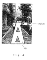
- FIG. 4 is a diagram showing an example of the display image, in which the optical axis AX and the forward direction of the guide route are the same, the guide route is present within the range of the peripheral image displayed on the screen, and a guide route image GRI for a right turn 30 m ahead of the imaging point is superimposed and drawn on the peripheral image.
- the image layout means 24 performs the calculation described above on the basis of the detection output of the attitude detection means 23 and determines the display position of the guide route image GRI.
- the peripheral image in the direction of advance may be captured by the imaging means 22 in a state wherein the portable terminal device 20 is held with the optical axis oriented horizontally.
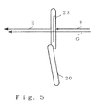
- the image is captured with the portable terminal device 20 held so that the normal to the display screen of the display means 28 of the portable terminal device 20 (arrow F) will be in alignment with the direction of the optical axis of the imaging means 22 (arrow E) and the line-of-sight direction of the user (arrow G), as shown in the schematic diagram of FIG. 5 .
- the peripheral image is captured in such a manner that the imaging means 22 comes into alignment with the position of the eye of the user at an attitude such that the display screen of the portable terminal device 20 is vertical (an attitude such that the optical axis is horizontal).
- the horizontal direction of the peripheral image displayed on the display screen of the display means 28 will be in alignment with the line-of-sight direction; and, as shown in FIG. 6 , the peripheral image 301 actually being viewed in the center of the display screen 300 will be displayed, while if the guide route direction has been imaged, the guide route RT will be displayed as a superimposed image on the peripheral image 301.
- the overlaying of the image is controlled in accordance with a peripheral image position and a guide route position computed by the image layout means 24.
- the portable terminal device 20 holding the portable terminal device 20 at such an attitude is unnatural for the user.
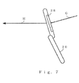
- the portable terminal device 20 it is natural for the portable terminal device 20 to be held at an attitude at which the line-of-sight direction (arrow G) is tilted at an angle of 30 to 60° downward from the horizontal direction for the screen of the display means 28 to be viewed, as shown in FIG. 7 .
- the user will not hold the portable terminal device 20 vertically when receiving navigational guidance. Holding the portable terminal device 20 upright can cause hand fatigue, while if the portable terminal device 20 is held directly in front of the eyes, the real view will be obstructed regardless of how much of the peripheral scene is reproduced (displayed) on the screen. This tends to make walking difficult.
- the optical axis of the imaging means 22 (arrow G in FIG. 7 ) will not be aligned with the horizontal direction (arrow H); therefore, the peripheral image displayed on the display screen of the display means 28 will not be aligned with the horizontal and will be displayed as an unnatural image.
- the imaging means 22 is essentially a camera, an image will not be readily captured if the optical axis of the imaging lens is not substantially parallel with the normal to the display screen. Accordingly, since the camera is used mainly for capturing peripheral images, it has been typically implicit in the past to regard the optical axis of the lens and the normal to the display screen as being parallel to one another, as with the system illustrated in Patent Document 7.
- the present invention is configured so that the display control means 25 is capable of controlling the position in which the peripheral image captured by the imaging means 22 is displayed on the display screen so that the center of the optical axis of the captured image will be positioned below the center of the display screen, and is capable of displaying the horizontal direction of the peripheral image on the display screen of the display means 28 even if the direction of the optical axis of the imaging means is directed downward from a horizontal line.
- FIG. 8 is a schematic diagram showing the relationship between the angle of view within which an image can be captured by the imaging means 22, and a position in which the peripheral image captured by the imaging means 22 is displayed on the display screen of the display means 28.
- the imaging means 22 which is a CCD camera or the like, is provided to the portable terminal device 20; and the maximum active pixel area of the display screen is determined according to the pixel area of the imaging means 22 (e.g., 1600 x 1200 dots).
- the image circle of the imaging lens is ordinarily larger than the maximum active pixel area; therefore, image data is obtained in any regions where there are active pixels. It is typical for the optical axis of the imaging lens to be located in the center of the maximum active pixel area.
- FIG. 8 shows a maximum angle of view ⁇ MAX obtained when the entire maximum active pixel area of the imaging means is used.
- the camera in the mobile telephone also has a zoom function; therefore, when the entire maximum active pixel area is used, the image will be at the wide angle end of the zoom.
- the image is too wide at the wide-angle end (distant images will be too small); therefore, the region of a conventional navigation screen 281, in which the pixels are concentrated to a certain degree, is used.
- the angle of view imaged by the imaging means 22 is also correspondingly smaller, as shown by ⁇ A, and is kept as the standard angle of view in navigation according to the prior art.
- the image will be shifted toward and displayed on the lower side of the display screen if the display region of the conventional live-image navigation screen 281 is set to a pixel region 282 upwardly shifted on the photographic-subject side; i.e., if the angle of view in live-image navigation according to the present invention is set to ⁇ B (the image is upside-down in the imaging means shown in FIG. 8 ; therefore, the region 282 towards the bottom in FIG. 8 is the screen of live-image navigation according to the present invention).
- the optical axis of the imaging means 22 is in a direction tilted downward from the horizontal line.
- the angle of view ⁇ B is the angle of view shifted according to the present invention.
- the optical axis of the imaging means 22 can be directed downward with respect to the horizontal direction; i.e., the portable terminal device 20 can be held to a degree of tilt that is commensurate with the shift of the screen, when the horizontal direction is viewed as shown in FIG. 7 (along arrow H).
- This enables the portable terminal device 20 to be tilted and held in a lower position than achievable with live-image navigation according to the prior art, and enables the line of sight (arrow G in FIG. 7 ) to be lowered.
- the display as described above is controlled by the display control means 25 as described with reference to FIGS. 8 and 9 .
- the display control means 25 compares the pixel region of the imaging element that constitutes the imaging means with the normal pixel region 281 for showing a map image on the display means 28, and sets a different pixel region; i.e., the pixel region 282, which is shifted downward on the display screen.
- the display control means 25 thereby controls the display position of the peripheral image captured by the imaging means so that the center of the optical axis of the imaging means 22 will be positioned lower than the center of the display screen. It will be possible to display the horizontal direction of the peripheral image on the display screen even if the optical axis of the imaging means 22 is directed downward from the horizontal line.
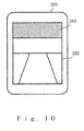
- the display is controlled as described above, then even if the portable terminal device is held with the display screen tilted with respect to the vertical direction, it will be possible to image and display photographic subjects in front of the user without having to orient the normal to the display screen in the direction of the photographic subject, as with the system according to Patent Document 7. If there is not enough space in the active pixel region 280 in a case where the degree of shift is increased to allow for an adequate degree of tilt, then a shaded region 283 in which no pixels are present can be employed as a region for displaying a variety of markings or selection button images for aiding navigation, as shown in FIG. 10 .
- the physical optical axis is not positioned in the center of the imaging lens, and the captured image is oriented more toward the periphery; therefore, in a strict sense, the captured peripheral image will be distorted.
- the degree to which the angle of view is tilted is known in advance for the distortion as well; therefore, it will be possible for the display control means 25 to display the peripheral image (live image) superimposed with information relating to the point of guidance (guide route information) present along the direction of the peripheral image.
- the display control means 25 shifts the display region, and displays the peripheral image in a display region that is different from the display region in a common navigation system. It is thus possible to tilt the portable terminal device 20 and capture an image in the foreground even if the line-of-sight direction is directed downward.
- certain cameras may be equipped with an anti-vibration optical system in order to prevent the terminal device from moving (shaking due to hand motion) when images are captured.
- the anti-vibration optical system in most instances an anti-vibration mechanism is provided to the imaging lens
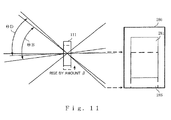
- shifting (raising) an imaging lens 111 upward as shown in FIG. 11 will produce the same effect as if the captured image has been shifted on the imaging element, as with the lower region 285.
- the amount of shift ⁇ performed by the anti-vibration optical system is typically small; therefore, this method alone is insufficient for achieving the effect. It is possible to incorporate the imaging element region shift in the above-described embodiment (see FIG. 8 ), and enhance the effect. Movement of the anti-vibration optical system is not cited by way of limitation; an optical system provided with a tilting mechanism may also be used.
- the database for route search network 35 is provided with road network data and transportation network data. These network data are configured as described below. For example, when the roads are composed of roads A, B, and C as shown in FIG. 12 , the end points, intersection points, turning points, and other points of roads A, B, and C are designated as nodes; roads linking the nodes are indicated by directional links; and the network data are composed of node data (node latitude/longitude), link data (link numbers), and link cost data in which link costs (distance between links or time required to travel to a link) between links are in the form of data.
- Nn and Nm indicate nodes, wherein Nm indicates an intersection of roads.
- Directional links between nodes are indicated by arrow lines (solid lines, dashed lines, chain double-dashed lines). Links in the upstream and downstream directions of the roads are present, but only links in the direction of the arrows are shown in FIG. 12 to simplify the diagram.
- transportation network data for a route search of transportation facilities are configured as described below.
- the transportation network data are composed of transportation lines A, B, and C as shown in FIG. 13
- train stations airports in the case of an airplane route
- intervals linking the nodes are indicated by directional links
- node data node latitude/longitude
- link data link numbers
- the reference symbols Nn and Nm indicate nodes, wherein Nm indicates a connection point (train-changing station or the like) between transportation routes, and directional links between nodes are indicated by arrow lines (solid lines, dashed lines, chain double-dashed lines). Links in the upstream and downstream directions of the roads are present, but only links in the direction of the arrows are shown in FIG. 13 to simplify the diagram.
- the link costs in a transportation network are fundamentally different from those of a road network.
- the link costs in the road network are fixed and static, whereas the transportation network has a plurality of trains or aircraft (trains, aircraft, and other routes are referred to hereinafter as modes of transportation) moving through the transportation lines, as shown in FIG. 13 .
- the times of departure from the nodes of each means of transportation are specific, as are the times of arrival at the subsequent nodes (specified in the timetable data and traffic data).
- the routes do not necessarily link to adjacent nodes. This situation occurs in the case of express trains and local trains, for example. In such a case, a plurality of different links exists on the same transportation line, and the time required to travel between nodes may change according to the mode of transportation.
- the example of the transportation network shown in FIG. 13 includes a plurality of transportation means (routes) Aa through Ac in the same link of a transportation line A, and a plurality of transportation means (routes) Ca through Cc in a transportation line C.
- the travel network of a transportation facility differs from a simple road network; the amount of data relating to nodes, links, and link costs therein is proportional to the sum total of the transportation means (routes of individual aircraft, trains, and the like).
- the amount of transportation network data is therefore extremely large in comparison to the amount of road network data. A correspondingly large amount of time is therefore needed to perform a route search.
- All transportation means that can be used (ridden) to travel from a departure point to a destination point must be searched, and a transportation means that satisfies the search conditions must be specified in order to search the route from a certain departure point to a certain destination point using the type of transportation network data described above.
- a guide route searched with reference to such network data is delivered to the portable terminal device 20 along with vector map data.
- the map data accumulated in the map database 34 is composed of unit map data that are divided into predetermined latitude/longitude ranges, as shown in FIG. 14 .
- the map data are divided into map areas by predetermined latitude/longitude units, as shown in FIG. 14 , and form a matrix of unit map data M11 through M33.
- the unit map data M22 that includes the current position PP of the portable terminal device 20 is at the center, and a total of nine unit maps made up of unit map data M21, M23, M12, M32, M11, M13, M31, and M33 are delivered that are adjacent to the unit map data M22 in the vertical, horizontal, and diagonal directions.
- the route search server 30 delivers the needed portion of unit map data.
- the same procedure applies when the portable terminal device 20 requests delivery of map data for a specific point or position of a POI (Point of Interest).
- the guide route data are delivered together with the vector map data to the portable terminal device 20.
- the portable terminal device 20 thus receives the map data and guide route data from the route search server 30 and displays the map and the guide route in the display means 28.
- a pedestrian navigation system for imaging a peripheral scene in intersections or other such locations using imaging means of a portable terminal device; for displaying the captured image on display means as a peripheral image; and, in a case where the portable terminal device is held at an attitude that is suitable for the user to view the display screen when a route guide image, a guidance image in a direction of advance, an icon image indicating a point of interest, or another image is to be displayed on top of the displayed peripheral image, for displaying a horizontal direction of the peripheral image on the display means even if a direction of an optical axis of the imaging means is directed downward from a horizontal line.
- the portable terminal device used in the present invention is not limited to mobile telephones; it may be used with imaging lenses and display screens of a digital camera.
- Digital cameras take large-capacity memory cards, and are accordingly able to have maps stored therein.
- a digital camera incorporating a GPS unit camera can also be used as a portable terminal device for use in navigation.
- Such portable terminal devices offer a high degree of convenience for those who travel.
- the portable terminal device need not be held in front of the face, but can be held lower down, which makes the display screen easier to see and allows the user to receive the route guides in the navigation system.
Landscapes
- Engineering & Computer Science (AREA)
- Radar, Positioning & Navigation (AREA)
- Remote Sensing (AREA)
- Physics & Mathematics (AREA)
- General Physics & Mathematics (AREA)
- Automation & Control Theory (AREA)
- Multimedia (AREA)
- Navigation (AREA)
- Mobile Radio Communication Systems (AREA)
- Instructional Devices (AREA)
- Processing Or Creating Images (AREA)
- Traffic Control Systems (AREA)
Applications Claiming Priority (1)
| Application Number | Priority Date | Filing Date | Title |
|---|---|---|---|
| PCT/JP2006/324270 WO2008068849A1 (ja) | 2006-12-05 | 2006-12-05 | ナビゲーションシステム、携帯端末装置および周辺画像表示方法 |
Publications (2)
| Publication Number | Publication Date |
|---|---|
| EP2090867A1 true EP2090867A1 (de) | 2009-08-19 |
| EP2090867A4 EP2090867A4 (de) | 2012-03-21 |
Family
ID=39078299
Family Applications (1)
| Application Number | Title | Priority Date | Filing Date |
|---|---|---|---|
| EP06834025A Withdrawn EP2090867A4 (de) | 2006-12-05 | 2006-12-05 | Navigationssystem, tragbares endgerät und verfahren zur anzeige eines peripheriebildes |
Country Status (6)
| Country | Link |
|---|---|
| US (1) | US20100070173A1 (de) |
| EP (1) | EP2090867A4 (de) |
| JP (1) | JP4038529B1 (de) |
| KR (1) | KR101039186B1 (de) |
| CN (1) | CN101583842B (de) |
| WO (1) | WO2008068849A1 (de) |
Families Citing this family (46)
| Publication number | Priority date | Publication date | Assignee | Title |
|---|---|---|---|---|
| US8171237B2 (en) | 2006-10-31 | 2012-05-01 | Yahoo! Inc. | Automatic association of reference data with primary process data based on time and shared identifier |
| JP5076468B2 (ja) * | 2006-12-01 | 2012-11-21 | 株式会社デンソー | 通信型ナビゲーションシステム、車両ナビゲーション装置及びセンター装置 |
| WO2008148782A1 (en) * | 2007-06-07 | 2008-12-11 | Qualcomm Incorporated | 3d maps rendering device and method |
| US8239132B2 (en) * | 2008-01-22 | 2012-08-07 | Maran Ma | Systems, apparatus and methods for delivery of location-oriented information |
| US8406531B2 (en) | 2008-05-15 | 2013-03-26 | Yahoo! Inc. | Data access based on content of image recorded by a mobile device |
| US9753948B2 (en) | 2008-05-27 | 2017-09-05 | Match.Com, L.L.C. | Face search in personals |
| US8098894B2 (en) | 2008-06-20 | 2012-01-17 | Yahoo! Inc. | Mobile imaging device as navigator |
| KR101320143B1 (ko) * | 2009-05-04 | 2013-10-23 | 주식회사 팬택 | 멀티미디어 데이터를 이용하여 위치를 관리하는 이동 단말 및 그 방법 |
| US20100277365A1 (en) * | 2009-05-04 | 2010-11-04 | Pantech Co., Ltd. | Mobile terminal to provide location management using multimedia data and method thereof |
| CN101886928A (zh) * | 2009-05-14 | 2010-11-17 | 深圳富泰宏精密工业有限公司 | 具有导盲功能的便携式电子装置 |
| KR101090804B1 (ko) | 2009-08-21 | 2011-12-08 | 현대자동차주식회사 | 액티브 지오메트리 컨트롤 서스펜션 |
| US8475371B2 (en) | 2009-09-01 | 2013-07-02 | Adidas Ag | Physiological monitoring garment |
| KR101001842B1 (ko) * | 2010-01-28 | 2010-12-17 | 팅크웨어(주) | 차량용 내비게이션 및 내비게이션 시스템의 블랙박스 정상 위치 유도 방법 |
| JP5472994B2 (ja) * | 2010-03-10 | 2014-04-16 | Necカシオモバイルコミュニケーションズ株式会社 | 撮像装置及びプログラム |
| US9691281B2 (en) * | 2010-03-24 | 2017-06-27 | Telenav, Inc. | Navigation system with image assisted navigation mechanism and method of operation thereof |
| JP5510007B2 (ja) * | 2010-04-01 | 2014-06-04 | 株式会社デンソー | 経路探索装置および経路案内システム |
| KR101572892B1 (ko) * | 2010-05-06 | 2015-11-30 | 엘지전자 주식회사 | 이동 단말기 및 이것의 영상 디스플레이 방법 |
| JP5548542B2 (ja) * | 2010-07-13 | 2014-07-16 | 富士通テン株式会社 | 携帯端末装置および駐車位置案内プログラム |
| CN102338639B (zh) * | 2010-07-26 | 2015-04-22 | 联想(北京)有限公司 | 信息处理设备和信息处理方法 |
| KR101732076B1 (ko) * | 2010-12-22 | 2017-05-02 | 엘지전자 주식회사 | 전자 기기 및 전자 기기의 제어 방법 |
| FR2971595B1 (fr) * | 2011-02-15 | 2013-03-22 | Snecma | Surveillance d'un moteur d'aeronef pour anticiper les operations de maintenance |
| CN103443839B (zh) * | 2011-03-28 | 2016-04-13 | 松下知识产权经营株式会社 | 图像显示装置 |
| US9116011B2 (en) * | 2011-10-21 | 2015-08-25 | Here Global B.V. | Three dimensional routing |
| WO2013136702A1 (ja) * | 2012-03-12 | 2013-09-19 | パナソニック株式会社 | 無線通信装置、無線通信方法、および無線通信制御プログラム |
| US9257054B2 (en) | 2012-04-13 | 2016-02-09 | Adidas Ag | Sport ball athletic activity monitoring methods and systems |
| US10922383B2 (en) * | 2012-04-13 | 2021-02-16 | Adidas Ag | Athletic activity monitoring methods and systems |
| JP5998777B2 (ja) * | 2012-09-12 | 2016-09-28 | ソニー株式会社 | 情報処理装置と情報処理方法とプログラムおよび情報処理システム |
| CN102879000A (zh) * | 2012-09-20 | 2013-01-16 | 华为终端有限公司 | 导航终端、导航方法及远程导航服务系统 |
| JP6071746B2 (ja) * | 2013-05-21 | 2017-02-01 | 三菱電機ビルテクノサービス株式会社 | 情報提供装置及び情報提供システム |
| JP2015059769A (ja) * | 2013-09-17 | 2015-03-30 | ソフトバンクモバイル株式会社 | 端末及び制御プログラム |
| JP6375633B2 (ja) * | 2014-02-12 | 2018-08-22 | 株式会社デンソー | 車両周辺画像表示装置、車両周辺画像表示方法 |
| US10932103B1 (en) * | 2014-03-21 | 2021-02-23 | Amazon Technologies, Inc. | Determining position of a user relative to a tote |
| US9429433B2 (en) * | 2014-11-07 | 2016-08-30 | Jennifer Hendrix | Route guidance and identification system |
| US10331140B2 (en) * | 2014-12-25 | 2019-06-25 | Equos Research Co., Ltd. | Moving body |
| US10001376B1 (en) * | 2015-02-19 | 2018-06-19 | Rockwell Collins, Inc. | Aircraft position monitoring system and method |
| US10495478B2 (en) | 2015-06-06 | 2019-12-03 | Apple Inc. | Feature selection in transit mode |
| US9702724B2 (en) | 2015-06-06 | 2017-07-11 | Apple Inc. | Mapping application with transit mode |
| US10302442B2 (en) * | 2015-06-07 | 2019-05-28 | Apple Inc. | Transit incident reporting |
| US10094675B2 (en) * | 2015-06-07 | 2018-10-09 | Apple Inc. | Map application with transit navigation mode |
| US9891065B2 (en) | 2015-06-07 | 2018-02-13 | Apple Inc. | Transit incidents |
| KR101866728B1 (ko) * | 2016-04-25 | 2018-06-15 | 현대자동차주식회사 | 네비게이션 장치, 차량 및 차량의 제어방법 |
| JP6700623B2 (ja) * | 2016-10-07 | 2020-05-27 | アイシン・エィ・ダブリュ株式会社 | 走行支援装置及びコンピュータプログラム |
| CN107223235B (zh) * | 2016-12-14 | 2022-02-25 | 达闼机器人有限公司 | 一种辅助显示方法、装置及显示系统 |
| US10172760B2 (en) | 2017-01-19 | 2019-01-08 | Jennifer Hendrix | Responsive route guidance and identification system |
| US20200370915A1 (en) * | 2018-03-23 | 2020-11-26 | Mitsubishi Electric Corporation | Travel assist system, travel assist method, and computer readable medium |
| JP7390910B2 (ja) * | 2020-01-31 | 2023-12-04 | 株式会社日立製作所 | 地図生成装置およびその方法 |
Family Cites Families (16)
| Publication number | Priority date | Publication date | Assignee | Title |
|---|---|---|---|---|
| US5815411A (en) | 1993-09-10 | 1998-09-29 | Criticom Corporation | Electro-optic vision system which exploits position and attitude |
| JPH0832841A (ja) * | 1994-07-12 | 1996-02-02 | Mitsubishi Electric Corp | ビデオ一体形カメラ |
| JP2000224461A (ja) * | 1999-02-02 | 2000-08-11 | Minolta Co Ltd | カメラシステム |
| JP3062488B1 (ja) | 1999-03-09 | 2000-07-10 | 株式会社スクウェア | テクスチャマッピング装置、方法、及び記録媒体 |
| JP3391311B2 (ja) | 1999-05-12 | 2003-03-31 | 株式会社デンソー | 地図表示装置 |
| JP2001165681A (ja) | 1999-12-09 | 2001-06-22 | Navitime Japan Co Ltd | 交通ネットワーク経路探索方法 |
| KR100353649B1 (ko) * | 2000-08-18 | 2002-09-28 | 삼성전자 주식회사 | 무선망을 이용한 네비게이션 시스템 및 그에 의한 경로안내 방법 |
| JP3848078B2 (ja) * | 2000-11-29 | 2006-11-22 | 株式会社エヌ・ティ・ティ・ドコモ | 方向提示方法及び携帯端末 |
| JP2004257979A (ja) | 2003-02-27 | 2004-09-16 | Sanyo Electric Co Ltd | ナビゲーション装置 |
| JP2004363815A (ja) * | 2003-06-03 | 2004-12-24 | Matsushita Electric Ind Co Ltd | カメラ付き携帯電話機 |
| US7406331B2 (en) * | 2003-06-17 | 2008-07-29 | Sony Ericsson Mobile Communications Ab | Use of multi-function switches for camera zoom functionality on a mobile phone |
| JP4433385B2 (ja) | 2004-02-25 | 2010-03-17 | ソニー・エリクソン・モバイルコミュニケーションズ株式会社 | 目的地案内装置および携帯端末装置 |
| JP2006162442A (ja) | 2004-12-07 | 2006-06-22 | Matsushita Electric Ind Co Ltd | ナビゲーション装置及びナビゲーション方法 |
| JP4632793B2 (ja) * | 2005-01-12 | 2011-02-16 | 京セラ株式会社 | ナビゲーション機能付き携帯型端末機 |
| JP4892741B2 (ja) * | 2005-03-30 | 2012-03-07 | 国立大学法人 熊本大学 | ナビゲーション装置およびナビゲーション方法 |
| JP2007094045A (ja) * | 2005-09-29 | 2007-04-12 | Matsushita Electric Ind Co Ltd | ナビゲーション装置、ナビゲート方法および車両 |
-
2006
- 2006-12-05 JP JP2007523914A patent/JP4038529B1/ja not_active Expired - Fee Related
- 2006-12-05 EP EP06834025A patent/EP2090867A4/de not_active Withdrawn
- 2006-12-05 KR KR1020097011503A patent/KR101039186B1/ko not_active Expired - Fee Related
- 2006-12-05 WO PCT/JP2006/324270 patent/WO2008068849A1/ja not_active Ceased
- 2006-12-05 US US12/517,116 patent/US20100070173A1/en not_active Abandoned
- 2006-12-05 CN CN2006800565405A patent/CN101583842B/zh not_active Expired - Fee Related
Also Published As
| Publication number | Publication date |
|---|---|
| CN101583842B (zh) | 2011-11-16 |
| JPWO2008068849A1 (ja) | 2010-03-11 |
| KR20090077853A (ko) | 2009-07-15 |
| US20100070173A1 (en) | 2010-03-18 |
| JP4038529B1 (ja) | 2008-01-30 |
| EP2090867A4 (de) | 2012-03-21 |
| KR101039186B1 (ko) | 2011-06-03 |
| WO2008068849A1 (ja) | 2008-06-12 |
| CN101583842A (zh) | 2009-11-18 |
Similar Documents
| Publication | Publication Date | Title |
|---|---|---|
| EP2090867A1 (de) | Navigationssystem, tragbares endgerät und verfahren zur anzeige eines peripheriebildes | |
| EP2080983B1 (de) | Navigationssystem, mobiles endgerät und routenführungsverfahren | |
| US6222583B1 (en) | Device and system for labeling sight images | |
| US20100250116A1 (en) | Navigation device | |
| US8315796B2 (en) | Navigation device | |
| JP4921462B2 (ja) | カメラ情報を有するナビゲーションデバイス | |
| US8352177B2 (en) | Navigation apparatus | |
| CN101427101B (zh) | 导航装置及其方法 | |
| JP2009020089A (ja) | ナビゲーション装置、ナビゲーション方法、及びナビゲーション用プログラム | |
| US20110288763A1 (en) | Method and apparatus for displaying three-dimensional route guidance | |
| KR100822814B1 (ko) | Gps/ins 장비를 이용한 측량 정보 및 gis 지리정보, 실시간 영상정보를 결합한 공간정보 서비스방법 | |
| KR100815153B1 (ko) | 카메라를 이용한 차량용 내비게이션의 교차로 안내 장치 및그 방법 | |
| JP6828934B1 (ja) | ナビゲーション装置、ナビゲーションシステム、ナビゲーション方法、ナビゲーションプログラム | |
| JP2008128827A (ja) | ナビゲーション装置およびナビゲーション方法ならびにそのプログラム | |
| CN102288180B (zh) | 实时影像导航系统及方法 | |
| RU2375756C2 (ru) | Навигационное устройство с информацией, получаемой от камеры | |
| KR100774591B1 (ko) | 네비게이션 시스템 및 이를 이용한 네비게이션 방법 | |
| JP3753306B2 (ja) | 移動体ナビゲーションシステム | |
| JP4428712B2 (ja) | ナビゲーションシステム、経路探索サーバ、端末装置および地図表示方法 | |
| JP2011022152A (ja) | ナビゲーションデバイス | |
| JPH1166349A (ja) | 移動量予測型景観ラベリング装置およびシステム |
Legal Events
| Date | Code | Title | Description |
|---|---|---|---|
| PUAI | Public reference made under article 153(3) epc to a published international application that has entered the european phase |
Free format text: ORIGINAL CODE: 0009012 |
|
| 17P | Request for examination filed |
Effective date: 20090604 |
|
| AK | Designated contracting states |
Kind code of ref document: A1 Designated state(s): AT BE BG CH CY CZ DE DK EE ES FI FR GB GR HU IE IS IT LI LT LU LV MC NL PL PT RO SE SI SK TR |
|
| DAX | Request for extension of the european patent (deleted) | ||
| A4 | Supplementary search report drawn up and despatched |
Effective date: 20120221 |
|
| RIC1 | Information provided on ipc code assigned before grant |
Ipc: G08G 1/005 20060101ALI20120215BHEP Ipc: G01C 21/00 20060101AFI20120215BHEP |
|
| STAA | Information on the status of an ep patent application or granted ep patent |
Free format text: STATUS: THE APPLICATION HAS BEEN WITHDRAWN |
|
| 18W | Application withdrawn |
Effective date: 20130410 |