EP2090876A2 - Torque testing device for a suspension hook of a clothes hanger - Google Patents
Torque testing device for a suspension hook of a clothes hanger Download PDFInfo
- Publication number
- EP2090876A2 EP2090876A2 EP09001802A EP09001802A EP2090876A2 EP 2090876 A2 EP2090876 A2 EP 2090876A2 EP 09001802 A EP09001802 A EP 09001802A EP 09001802 A EP09001802 A EP 09001802A EP 2090876 A2 EP2090876 A2 EP 2090876A2
- Authority
- EP
- European Patent Office
- Prior art keywords
- hanger
- torque
- suspension hook
- station
- hook
- Prior art date
- Legal status (The legal status is an assumption and is not a legal conclusion. Google has not performed a legal analysis and makes no representation as to the accuracy of the status listed.)
- Granted
Links
Images


Classifications
-
- G—PHYSICS
- G01—MEASURING; TESTING
- G01M—TESTING STATIC OR DYNAMIC BALANCE OF MACHINES OR STRUCTURES; TESTING OF STRUCTURES OR APPARATUS, NOT OTHERWISE PROVIDED FOR
- G01M99/00—Subject matter not provided for in other groups of this subclass
- G01M99/007—Subject matter not provided for in other groups of this subclass by applying a load, e.g. for resistance or wear testing
-
- B—PERFORMING OPERATIONS; TRANSPORTING
- B65—CONVEYING; PACKING; STORING; HANDLING THIN OR FILAMENTARY MATERIAL
- B65G—TRANSPORT OR STORAGE DEVICES, e.g. CONVEYORS FOR LOADING OR TIPPING, SHOP CONVEYOR SYSTEMS OR PNEUMATIC TUBE CONVEYORS
- B65G33/00—Screw or rotary spiral conveyors
- B65G33/02—Screw or rotary spiral conveyors for articles
-
- G—PHYSICS
- G01—MEASURING; TESTING
- G01L—MEASURING FORCE, STRESS, TORQUE, WORK, MECHANICAL POWER, MECHANICAL EFFICIENCY, OR FLUID PRESSURE
- G01L5/00—Apparatus for, or methods of, measuring force, work, mechanical power, or torque, specially adapted for specific purposes
- G01L5/0028—Force sensors associated with force applying means
- G01L5/0042—Force sensors associated with force applying means applying a torque
-
- B—PERFORMING OPERATIONS; TRANSPORTING
- B65—CONVEYING; PACKING; STORING; HANDLING THIN OR FILAMENTARY MATERIAL
- B65G—TRANSPORT OR STORAGE DEVICES, e.g. CONVEYORS FOR LOADING OR TIPPING, SHOP CONVEYOR SYSTEMS OR PNEUMATIC TUBE CONVEYORS
- B65G2201/00—Indexing codes relating to handling devices, e.g. conveyors, characterised by the type of product or load being conveyed or handled
- B65G2201/02—Articles
- B65G2201/0229—Clothes, clothes hangers
Definitions
- the invention relates to a torque-testing device for a suspension hook of a hanger.
- An existing plastic hanger usual construction has a hanger body which carries in its central region on its upper side an upwardly projecting suspension hook and having two extending to opposite sides of the hanger hook arms.
- the suspension hook is made of metal and is embedded at its lower end in the plastic material of the hanger body.
- plastic hangers For some time, efforts have been made to use plastic hangers several times. For this purpose, the plastic hangers that remain after the sale of the garment at the retailer, collected again, checked for any damage and then brought to the manufacturer of the garments and reused from this. However, it has been shown that in particular the end consumers in the retail trade destroy the non-rotatable holder of the suspension hook in the hanger body in order to suspend a garment hanging on the hanger transversely to the previous orientation and thereby be able to better look at it.
- the used hangers are usually not examined whether the suspension hook is still clamped with sufficient strength in the bracket body and thus can absorb a sufficiently large torque.
- the sorters pick up each hanger and sometimes also turn the hanger hook to see if it is overly loose.
- the invention has for its object to provide a torque-testing device for a suspension hook of a hanger, with the reliable can be determined whether a hanger is suitable for use in sorting and conveying systems.
- the torque-testing device detects a test station, which is associated with a holding device by means of which the hanger can be firmly held and fixed.
- the test station is associated with a test head, with the connection between the suspension hook and a hanger body of the hanger in at least one direction of rotation and preferably in both Turning a torque of predetermined size can be applied.
- this hanger If the suspension hook rotates due to the predetermined torque, for example, 0.6Nm relative to the bracket body, this hanger is not suitable for further use in automatic sorting and conveying systems and is rejected as a so-called “bad hanger” or fed to an additional workup, in which Suspension hook is subsequently fixed again rotatably. If the connection between the hanger body and the suspension hook can absorb the torque, the hanger can continue to be used and is classified as a so-called "Gutbügel".
- the holding device of the hanger With the holding device of the hanger is held in particular on his hanger body in the test station.
- the test head is brought into abutment with the suspension hook and then the predetermined torque is applied by the test head to the suspension hook.
- the movement of the suspension hook relative to the hanger body as a result of the applied torque is detected and in an evaluation unit the hanger currently checked is classified as either a "bad-iron” or a "good-iron". Only the hangers classified as "gutters" are put to further use, while the "bad hangers” are sorted out and preferably shredded or shredded, which can also be done immediately after passing through the torque testing device.
- a torque is applied to the connection between the hanger body and the hanger hook of the hanger.
- this can be achieved by fixing the hanger body of the hanger and applying the torque directly to the hanger hook.
- it is also possible to fix the suspension hook and apply the torque to the hanger body, in each case it is checked whether an excessively large relative rotation occurs between the hanger body and the suspension hook.
- a conveying device is provided, by means of which the hanger of the testing station can be fed.
- the conveyor device may be, for example, a transport spindle or screw, which is rotationally driven and on which a multiplicity of clothes hangers are each suspended with their suspension hooks one behind the other.
- the hanger supplied to the test station can have different design, different size and different design, as can be checked with the torque tester virtually all hanger types in which a preferably metal hanging hook sits in a preferably made of plastic hanger body.
- the hangers are in discontinuous sequence on the conveyor.
- the checking station is preceded by a separating station for separating the clothes hanger fed to the testing station.
- the separating station ensures that only one hanger ever enters the testing station and that the following hanger maintains a sufficient distance.
- the separating station can be, for example, a stop which can be moved into the transport path of the hanger along the conveying device and withdrawn therefrom.
- the stopper is positioned so that the hangers rest against the stop with their lower, vertical portion of the suspension hook.
- the separating station is preceded by a pre-separating station.
- the pre-separation station preferably comprises a stop which can be retracted into the transport path of the hanger along the conveyor and withdrawn from it.
- the pre-separating station has the purpose of preventing an excessive traffic jam from building up on hangers in the separating station and impairing the resulting dynamic pressure as a function of the testing device.
- a hook stop be provided, with which the suspension hook of the supplied hanger is brought into abutment or runs on this.
- the hook stop is preferably located at the end of the conveyor.
- the hook stop at least one magnet is integrated, with which the suspension hook of the hanger can be brought into abutment.
- the hanger with its metal suspension hook comes close to the magnet, it pulls on the suspension hook so that the hanger is in close contact with the hook stop and preferably rests against the magnet over its entire surface.
- the magnet ensures that there is no gap of indefinite dimension between the hook stop and the suspension hook.
- at least two spaced-apart magnets should be provided. The magnets are perpendicular to the longitudinal extent of the conveyor and transversely spaced therefrom, and engage with different portions of the upper, curved portion of the suspension hook. This ensures that the suspension hook rests in the desired orientation on the hook stop.
- a hanger In order to start the actual testing process for the torque, it must first be determined that a hanger is present in the test station. In addition, it should preferably be determined that the hanger to be checked is correctly positioned in the test station.
- the hook stop a Sensor device is assigned by means of the presence of a hanger can be detected.
- this sensor device may comprise at least two contacts of a circuit. As the hanger struts against the hook stop and thus the contacts with its metal hook, the circuit is closed, which is detected and can serve as a signal for the presence of a garment hanger.
- This embodiment has the significant advantage that not only the presence of the hanger in the test station, but also its correct positioning in the test station can be detected by the closing of the circuit due to the investment of the hanger hook of the hanger on the contacts.
- the contacts may be provided independently or in addition to the magnets, in a preferred embodiment of the invention, however, it is provided that the contacts are integrated into the magnets.
- the hanger hook is brought into engagement with the test head.
- the test head may be a test clip, between the clip legs or jaws of the suspension hook or the bracket body is clamped.
- the test clip is connected to a rotary drive and preferably a bidirectional rotary drive, so that in one step, the predetermined torque can be applied in both directions of rotation of the suspension hook. In this case, the predetermined torque should be infinitely adjustable by a user.
- the rotary drive can be electrically operated. Alternatively, it is also possible to use a pneumatic or hydraulic rotary drive.
- the holding device by means of which the hanger is held in the test station, may also comprise at least one retaining clip, between the retaining legs of the hanger is clamped.
- the hanger is preferably gripped by means of the holding device away from the suspension hook and preferably on its hanger body.
- At least two retaining clips are provided, which are engageable with the hanger body of the hanger on opposite ends of the suspension hook, for example in the central regions or in the outer end regions of the hanger body.
- the hanger is classified by the evaluation unit as "Gutbügel" and preferably placed on a forwarding transport device, which leads to a packaging station or other treatment station leads.
- the hanger If the suspension hook can be rotated excessively in at least one direction of rotation due to the applied torque relative to the hanger body, the hanger is classified by the evaluation unit as a "bad hanger", resulting in that the hanger after leaving the test station either sorted out or an additional refurbishment fed in at the suspension hook is subsequently fixed again rotatably, or immediately destroyed or shredded.
- the advantage is given that after the review only "Gutbügel” exist, ie hangers, the suspension hook is sufficiently fixed, so that even later confusion can no longer occur.
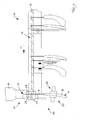
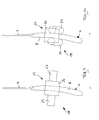
- FIG. 1 shows a schematic side view of a torque-testing device 10 according to the invention for a suspension hook H of a hanger K.
- the test apparatus 10 comprises a conveying device 11 in the form of a rotationally driven, rod-shaped transport spindle 12, which is oriented substantially horizontally and in discontinuous sequence Variety of hangers K of different design are hung, as is in FIG. 1 is indicated.
- the transport spindle 12 By rotation of the transport spindle 12, the hangers K in the transport direction T, ie according to FIG. 1 be transported from right to left in a hanging orientation.
- a test station 20 is arranged, which has a hook stop 17, against which the hanger K to be checked runs up with its suspension hook H.
- a separation station 14 for separating the test station 20 supplied hanger K provided.
- the separating station 14 comprises two bolt-like stops 15 and 16, which can be extended transversely to the transport direction T in the transport path of the hangers K in the region of the lower ends of the respective suspension hook H and withdrawn from the transport path.
- a pre-separating station 13 In the transport direction T before the separating station 14, i. upstream of the separating station 14, a pre-separating station 13 is provided, which has a further adjustable stop pin 13a, which is selectively introduced into the transport path of the hanger K and retractable from this.
- FIG. 12 attaches the suspension hook H of the hanger K with its upper curved portion to the hook stopper 17 while it is still suspended on the transport spindle 12 of the conveyor 11.
- a sensor device 31 is integrated, which detects the presence of a hanger K and its correct positioning.
- the sensor device 31 has two magnets 18 arranged laterally next to each other in the transverse direction to the transport direction T, which engage and attract the upper curved portion of the suspension hook H of the hanger K.
- a contact 32 of a circuit is integrated in each magnet 18, a contact 32 of a circuit is integrated. As soon as the metal suspension hook H bears against the magnet 18 and thus with the contacts 32, the circuit is closed, which is detected in a manner not shown. In this way it is ensured that when closing the circuit both a hanger K is present and positioned correctly.
- a test head 21 is arranged in the test station 20, which has a test clip 22 with two relatively mutually pivotable clip legs 23, as indicated by the arrows Z in FIG. 1 is indicated.
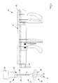
- the clip legs 23 can clamp the suspension hook H, which bears against the hook stop 17, between them (see FIG FIG. 2 ), wherein the hook stop 17 is encompassed by the clip legs 23 and thus the hanging hook H initially in its resting on the hook stop 17, held by the magnets 18 position remains.
- the test head 21 further comprises a bidirectional rotary drive 24, by means of which the test clip 22 is rotatable about a vertical axis V in both directions of rotation.
- a predetermined torque can be applied to the suspension hook H via the test clip 22, with the resulting movements being detected and evaluated via an evaluation unit 30 that is shown only schematically.
- a holding device 25 is arranged in the test station 20, which has two retaining clips 28, each comprising a base part 26 and two support legs 27 pivotally mounted thereto. Each retaining clip 28 can engage with a hanger body B of the hanger K on opposite sides of the hanger hook and thus fix the hanger K (see FIGS. 9, 10 and 11 ).
- the hanger K is fed by means of the conveyor 11 of the test station 20 and lays down with its hook H to the hook stop 17 and is held there by the magnets 18 in a predetermined position.
- the separating station 14 and the pre-separating station 13 prevent subsequent hangers interfere with the review.
- the test clip 22 of the probe 21 is still in the open position and also the retaining clips 28 of the holding device 25 are still open. This condition is in FIG. 1 shown.
- test clip 22 is closed, so that the clip legs 23 clamp the suspension hook H between them.
- This condition is in FIG. 2 shown.
- the suspension hook H initially bears against the magnet 18 of the hook stop 17.
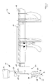
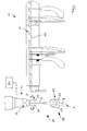
- the hook stop 17 is moved downward (see arrow R in FIG. 3 ), so that the test station 20 can be moved laterally in the transport direction T (see arrow H in FIG. 3 ) and the hanger K passes over the lowered hook stop 17, so that the hanger K is completely released from the hook stop 17, as shown in FIG FIG. 4 is shown. Then, the retaining clips 28 of the holding device 25 are closed and detect the hanger body B of the hanger K (s. FIG. 5 ).
- a predetermined torque is applied to the suspension hook H in both directions of rotation, as in FIG. 6 indicated by the double arrow D.
- the rotary drive 24 first brings the predetermined torque in a first rotational direction D1 (see FIG. 11 ) on the test bracket 22 on the suspension hook H, wherein the hanger is firmly clamped on the two retaining clips 28 of the holding device 25 on the hanger body B. Subsequently, a predetermined torque is applied in the other rotational direction D2 via the rotary drive 24.
- the hanger K of the evaluation unit 30 If the attachment of the suspension hook H in the hanger body B of the hanger K can absorb the torque, so that except elastic deformations no significant relative rotation between the hanger body B and the suspension hook H occur, the hanger K of the evaluation unit 30 as a reusable "Gutbügel "classified. Otherwise, the hanger K is classified as a "bad hanger".
- the test head 21 moves with the holding device 25 and the fixed clothes hanger K to a further transport device 29 (see FIG. Figure 7 ), on which the hanger K is hung with its suspension hook H.
- the further transport device 29 has a switch, which is controlled by the evaluation unit 30. If the hanger K is classified as a "gutter”, the switch is set so that the hanger K is transported to another workstation, such as a sorting station or a packing station. If the hanger K is classified as a "bad hanger", the switch is set so that the hanger is sorted out or one Processing station or a destruction station, for example, a shredder is supplied.
- both the test clip 22 of the probe 21 and the retaining clips 28 of the holding device 25 are opened, so that the hanger K released is transported and either due to its own weight and / or by motor drive along the secondary transport device 29 (see arrow S in FIG. 8 ). This concludes the inspection and classification of the hanger with regard to the torsional strength of its suspension hook.
Landscapes
- Physics & Mathematics (AREA)
- General Physics & Mathematics (AREA)
- Engineering & Computer Science (AREA)
- Mechanical Engineering (AREA)
- Chemical & Material Sciences (AREA)
- Analytical Chemistry (AREA)
- Chain Conveyers (AREA)
- Holders For Apparel And Elements Relating To Apparel (AREA)
Abstract
Eine Drehmoment-Prüfvorrichtung für einen Aufhängehaken eines Kleiderbügels weist eine Prüfstation und eine der Prüfstation zugeordnete Haltevorrichtung auf, mittels der der Kleiderbügel fixierbar ist. Mit einem Prüfkopf kann auf die Verbindung zwischen dem Aufhängehaken und einem Bügelkörper des Kleiderbügels in zumindest einer Drehrichtung ein Drehmoment vorbestimmter Größe aufgebracht werden und es ist eine Auswerteeinheit vorgesehen, die den Kleiderbügel aufgrund der infolge des aufgebrachten Drehmoments erfolgten Bewegung zwischen dem Bügelkörper und dem Aufhängehaken klassifiziert.A torque test device for a hanging hook of a clothes hanger has a test station and a holding device associated with the test station, by means of which the hanger is fixable. With a test head, a torque of predetermined size can be applied to the connection between the suspension hook and a hanger body of the hanger in at least one direction of rotation, and an evaluation unit is provided which classifies the hanger on the basis of the applied torque between the hanger body and the suspension hook ,
Description
Die Erfindung betrifft eine Drehmoment-Prüfvorrichtung für einen Aufhängehaken eines Kleiderbügels.The invention relates to a torque-testing device for a suspension hook of a hanger.
Ein aus Kunststoff bestehender Kleiderbügel üblichen Aufbaus besitzt einen Bügelkörper, der in seinem mittleren Bereich auf seiner Oberseite einen nach oben hervorstehenden Aufhängehaken trägt und der zwei sich zu entgegengesetzten Seiten des Aufhängehakens erstreckende Bügelarme aufweist. Der Aufhängehaken besteht aus Metall und ist an seinem unteren Ende in das Kunststoff-Material des Bügelkörpers eingebettet.An existing plastic hanger usual construction has a hanger body which carries in its central region on its upper side an upwardly projecting suspension hook and having two extending to opposite sides of the hanger hook arms. The suspension hook is made of metal and is embedded at its lower end in the plastic material of the hanger body.
In der Bekleidungsindustrie werden die Kleidungsstücke üblicherweise bereits unmittelbar nach ihrer Herstellung auf einen Kleiderbügel aufgebügelt und zusammen mit diesem zum Großhändler, Zwischenhändler und anschließend zum Einzelhändler transportiert. Dabei durchlaufen die Kleidungsstücke zusammen mit dem Kleiderbügel in der Regel vollautomatische Förder- und Sortieranlagen. Um den kontinuierlichen, ordnungsgemäßen Betrieb entsprechender Förder- und Sortieranlagen sicherzustellen, muss gewährleistet sein, dass der Aufhängehaken sich relativ zu dem Bügelkörper nicht dreht oder zumindest ein Drehmoment ausreichender Größe aufnehmen kann. Dies wird bei Kleiderbügeln mit einem aus Kunststoff bestehenden Bügelkörper und einem metallenen Aufhängehaken üblicherweise dadurch erreicht, dass das untere Ende des Aufhängehakens drehfest in dem Kunststoff-Material des Bügelkörpers festgelegt wird. Auf diese Weise lässt sich sicherstellen, dass bei einem neu hergestellten Kleiderbügel des genannten Aufbaus beim Durchlaufen der Sortier- und Förderanlagen keine Relativdrehung zwischen dem Aufhängehaken und dem Bügelkörper auftritt.In the apparel industry, garments are usually ironed on a hanger as soon as they are made and then transported with them to the wholesaler, middleman and then to the retailer. As a rule, the garments, together with the hanger, pass through fully automatic conveying and sorting systems. To ensure the continuous, proper operation of appropriate conveyor and sorting systems ensure that the hanger does not rotate relative to the hanger body or at least can absorb a torque of sufficient magnitude. This is usually achieved in garment hangers with a plastic hanger body and a metal hanging hook, that the lower end of the suspension hook is rotatably fixed in the plastic material of the hanger body. In this way it can be ensured that in a newly manufactured hanger of said structure when passing through the sorting and conveying systems no relative rotation between the suspension hook and the hanger body occurs.
Seit einiger Zeit ist man bemüht, Kunststoff-Kleiderbügel mehrfach zu verwenden. Zu diesem Zweck werden die Kunststoff-Kleiderbügel, die nach dem Verkauf des Kleidungsstückes beim Einzelhändler übrig bleiben, wieder eingesammelt, auf eventuelle Beschädigungen überprüft und anschließend zum Hersteller der Kleidungsstücke gebracht und von diesem wiederverwendet. Es hat sich jedoch gezeigt, dass insbesondere die Endverbraucher beim Einzelhandel die drehfeste Halterung des Aufhängehakens im Bügelkörper zerstören, um ein auf dem Kleiderbügel hängendes Kleidungsstück quer zur bisherigen Ausrichtung aufhängen und dadurch besser betrachten zu können. Darüber hinaus kann es vorkommen, dass sich die Einspannung des unteren Endes des Aufhängehakens in dem Kunststoff-Material des Bügelkörpers auf dem Transport etwas verringert hat, so dass die Aufbringung eines bereits relativ geringen Drehmomentes ausreicht, um die Halterung zwischen dem Aufhängehaken und dem Bügelkörper zu lösen, so dass der Aufhängehaken drehbar wird, womit beim Transport in den Sortier- und Förderanlagen die vorgenannten Probleme verbunden sind.For some time, efforts have been made to use plastic hangers several times. For this purpose, the plastic hangers that remain after the sale of the garment at the retailer, collected again, checked for any damage and then brought to the manufacturer of the garments and reused from this. However, it has been shown that in particular the end consumers in the retail trade destroy the non-rotatable holder of the suspension hook in the hanger body in order to suspend a garment hanging on the hanger transversely to the previous orientation and thereby be able to better look at it. In addition, it may happen that the clamping of the lower end of the suspension hook has been slightly reduced in the plastic material of the hanger body on the transport, so that the application of an already relatively low torque is sufficient to the holder between the suspension hook and the hanger body solve, so that the suspension hook is rotatable, which are connected during transport in the sorting and conveying the aforementioned problems.
Die gebrauchten Kleiderbügel werden üblicherweise nicht darauf untersucht, ob der Aufhängehaken noch mit einer ausreichenden Festigkeit in den Bügelkörper eingespannt ist und somit ein ausreichend großes Drehmoment aufnehmen kann. Wenn die gebrauchten Kleiderbügel manuell sortiert werden, um sie hinsichtlich ihrer Form, Größe, Bauart, Materialien etc. zu unterscheiden, nehmen die Sortierpersonen jeden Kleiderbügel in die Hand und drehen dabei manchmal auch am Aufhängehaken um festzustellen, ob dieser übermäßig locker sitzt. Eine definierte Prüfung des Drehmoments, das vom Aufhängehaken an seiner unteren Einspannung im Bügelkörper aufnehmbar ist, ist auf diese Weise jedoch nicht gegeben. Aus diesem Grunde häufen sich die Betriebsstörungen in automatischen Sortier- und Förderanlagen der Bekleidungsindustrie, sobald Kleidungsstücke auf gebrauchten Kleiderbügeln die Anlagen durchlaufen.The used hangers are usually not examined whether the suspension hook is still clamped with sufficient strength in the bracket body and thus can absorb a sufficiently large torque. When the used hangers are manually sorted to distinguish them in shape, size, construction, materials, etc., the sorters pick up each hanger and sometimes also turn the hanger hook to see if it is overly loose. A defined test of the torque that can be absorbed by the suspension hook at its lower clamping in the hanger body, however, is not given in this way. For this reason, the malfunctions accumulate in automatic sorting and conveying systems of the clothing industry, as soon as garments on used hangers go through the plants.
Der Erfindung liegt die Aufgabe zugrunde, eine Drehmoment-Prüfvorrichtung für einen Aufhängehaken eines Kleiderbügels zu schaffen, mit der zuverlässig festgestellt werden kann, ob ein Kleiderbügel für den Einsatz in Sortier- und Förderanlagen geeignet ist.The invention has for its object to provide a torque-testing device for a suspension hook of a hanger, with the reliable can be determined whether a hanger is suitable for use in sorting and conveying systems.
Diese Aufgabe wird erfindungsgemäß mit einer Drehmoment-Prüfvorrichtung mit den Merkmalen des Anspruchs 1 gelöst. Dabei ist vorgesehen, dass die Drehmoment-Prüfvorrichtung eine Prüfstation erfasst, der eine Haltevorrichtung zugeordnet ist, mittels der der Kleiderbügel fest gehalten und fixiert werden kann. Darüber hinaus ist der Prüfstation ein Prüfkopf zugeordnet, mit dem auf die Verbindung zwischen dem Aufhängehaken und einem Bügelkörper des Kleiderbügels in zumindest einer Drehrichtung und vorzugsweise in beide Drehrichtungen ein Drehmoment vorbestimmter Größe aufgebracht werden kann. Wenn sich der Aufhängehaken infolge des vorgegebenen Drehmomentes von beispielsweise 0,6Nm relativ zum Bügelkörper dreht, ist dieser Kleiderbügel für die weitere Verwendung in automatischen Sortier- und Förderanlagen nicht geeignet und wird als sogenannter "Schlechtbügel" ausgesondert oder einer zusätzlichen Aufarbeitung zugeführt, bei der der Aufhängehaken nachträglich wieder drehfest fixiert wird. Wenn die Verbindung zwischen dem Bügelkörper und dem Aufhängehaken das Drehmoment aufnehmen kann, kann der Kleiderbügel weiterhin verwendet werden und wird als sogenannter "Gutbügel" eingestuft.This object is achieved with a torque tester with the features of claim 1. It is provided that the torque-testing device detects a test station, which is associated with a holding device by means of which the hanger can be firmly held and fixed. In addition, the test station is associated with a test head, with the connection between the suspension hook and a hanger body of the hanger in at least one direction of rotation and preferably in both Turning a torque of predetermined size can be applied. If the suspension hook rotates due to the predetermined torque, for example, 0.6Nm relative to the bracket body, this hanger is not suitable for further use in automatic sorting and conveying systems and is rejected as a so-called "bad hanger" or fed to an additional workup, in which Suspension hook is subsequently fixed again rotatably. If the connection between the hanger body and the suspension hook can absorb the torque, the hanger can continue to be used and is classified as a so-called "Gutbügel".
Mit der Haltevorrichtung wird der Kleiderbügel insbesondere an seinem Bügelkörper in der Prüfstation festgehalten. Der Prüfkopf wird mit dem Aufhängehaken in Anlage gebracht und anschließend wird von dem Prüfkopf auf den Aufhängehaken das vorbestimmte Drehmoment aufgebracht. Die infolge des aufgebrachten Drehmoments erfolgte Bewegung des Aufhängehakens relativ zu dem Bügelkörper wird erfasst und in einer Auswerte-Einheit wird der aktuell überprüfte Kleiderbügel entweder als "Schlecht-bügel" oder als "Gutbügel" klassifiziert. Nur die als "Gutbügel" klassifizierten Kleiderbügel werden einer weitere Verwendung zugeführt, während die "Schlechtbügel" aussortiert und vorzugsweise zerkleinert bzw. geschreddert werden, was auch unmittelbar nach Durchlaufen der Drehmoment-Prüfvorrichtung erfolgen kann.With the holding device of the hanger is held in particular on his hanger body in the test station. The test head is brought into abutment with the suspension hook and then the predetermined torque is applied by the test head to the suspension hook. The movement of the suspension hook relative to the hanger body as a result of the applied torque is detected and in an evaluation unit the hanger currently checked is classified as either a "bad-iron" or a "good-iron". Only the hangers classified as "gutters" are put to further use, while the "bad hangers" are sorted out and preferably shredded or shredded, which can also be done immediately after passing through the torque testing device.
Wenn die Drehmoment-Prüfvorrichtung in eine Förder- und Sortieranlage integriert oder unmittelbar vor dieser positioniert wird, ist es möglich, die Drehfestigkeit des Aufhängehakens eines Kleiderbügels unmittelbar vor oder sogar innerhalb der Förder- und Sortieranlage zu überprüfen, wodurch zuverlässig ausgeschlossen ist, dass Kleiderbügel mit einem drehbaren Aufhängehaken die Förder- und Sortieranlage durchlaufen.When the torque tester is integrated with or positioned immediately before a conveyor and sorting system, it is possible to check the torsional rigidity of the hanger hook of a hanger immediately before or even inside the conveyor and sorting system, thereby It is reliably ruled out that hangers with a rotatable suspension hook go through the conveyor and sorting system.
Bei der Drehmoment-Prüfvorrichtung wird auf die Verbindung zwischen dem Bügelkörper und dem Aufhängehaken des Kleiderbügels ein Drehmoment aufgebracht. Dies kann einerseits dadurch geschehen, dass der Bügelkörper des Kleiderbügels fixiert und das Drehmoment unmittelbar auf den Aufhängehaken aufgebracht wird. In kinematischer Umkehr ist es jedoch auch möglich, den Aufhängehaken zu fixieren und das Drehmoment auf den Bügelkörper aufzubringen, wobei jeweils überprüft wird, ob zwischen dem Bügelkörper und dem Aufhängehaken eine übermäßig große relative Drehung auftritt.In the torque tester, a torque is applied to the connection between the hanger body and the hanger hook of the hanger. On the one hand, this can be achieved by fixing the hanger body of the hanger and applying the torque directly to the hanger hook. In kinematic reversal, however, it is also possible to fix the suspension hook and apply the torque to the hanger body, in each case it is checked whether an excessively large relative rotation occurs between the hanger body and the suspension hook.
In bevorzugter Ausgestaltung der Erfindung ist eine Fördervorrichtung vorgesehen, mittels der der Kleiderbügel der Prüfstation zuführbar ist. Bei der Fördervorrichtung kann es sich beispielsweise um eine Transport-Spindel oder -Schnecke handeln, die drehangetrieben ist und auf der eine Vielzahl von Kleiderbügeln jeweils mit ihrem Aufhängehaken hintereinander aufgehängt sind. Infolge der Drehung der Transport-Spindel werden die Aufhängehaken und damit der Kleiderbügel längs der Transport-Spindel vorgeschoben und auf diese Weise der Prüfstation zugeführt. Die der Prüfstation zugeführten Kleiderbügel können dabei unterschiedliche Bauart, unterschiedliche Größe und unterschiedliche Gestaltung aufweisen, da sich mit der Drehmoment-Prüfvorrichtung praktisch alle Kleiderbügel-Typen überprüfen lassen, bei denen ein vorzugsweise metallener Aufhängehaken in einem vorzugsweise aus Kunststoff bestehenden Bügelkörper sitzt.In a preferred embodiment of the invention, a conveying device is provided, by means of which the hanger of the testing station can be fed. The conveyor device may be, for example, a transport spindle or screw, which is rotationally driven and on which a multiplicity of clothes hangers are each suspended with their suspension hooks one behind the other. As a result of the rotation of the transport spindle, the suspension hook and thus the hanger are fed along the transport spindle and fed to the test station in this way. The hanger supplied to the test station can have different design, different size and different design, as can be checked with the torque tester virtually all hanger types in which a preferably metal hanging hook sits in a preferably made of plastic hanger body.
Üblicherweise befinden sich die Kleiderbügel in diskontinuierlicher Folge auf der Fördervorrichtung. Um zu verhindern, dass durch zwei sehr eng aufeinanderfolgende Kleiderbügel die Bestimmung der Drehfestigkeit des Aufhängehakens des vorlaufenden Kleiderbügels in der Prüfstation beeinträchtigt wird, kann in Weiterbildung der Erfindung vorgesehen sein, dass der Prüfstation eine Vereinzelungsstation zur Vereinzelung der der Prüfstation zugeführten Kleiderbügel vorgelagert ist. Die Vereinzelungsstation stellt sicher, dass immer nur ein Kleiderbügel in die Prüfstation eintritt und dass der nachfolgende Kleiderbügel einen ausreichenden Abstand einhält. Bei der Vereinzelungsstation kann es sich beispielsweise um einen Anschlag handeln, der in den Transportweg der Kleiderbügel längs der Fördervorrichtung eingefahren und aus diesem zurückgezogen werden kann. Vorzugsweise ist der Anschlag so positioniert, dass die Kleiderbügel sich mit ihrem unteren, vertikalen Abschnitt des Aufhängehakens an den Anschlag anlegen.Usually, the hangers are in discontinuous sequence on the conveyor. In order to prevent the determination of the rotational strength of the suspension hook of the leading clothes hanger in the testing station being adversely affected by two very closely successive hangers, it can be provided in a further development that the checking station is preceded by a separating station for separating the clothes hanger fed to the testing station. The separating station ensures that only one hanger ever enters the testing station and that the following hanger maintains a sufficient distance. The separating station can be, for example, a stop which can be moved into the transport path of the hanger along the conveying device and withdrawn therefrom. Preferably, the stopper is positioned so that the hangers rest against the stop with their lower, vertical portion of the suspension hook.
In bevorzugter Ausgestaltung der Erfindung ist vorgesehen, dass der Vereinzelungsstation eine Vor-Vereinzelungsstation vorgeschaltet ist. Auch die Vor-Vereinzelungsstation umfasst vorzugsweise einen Anschlag, der in den Transportweg der Kleiderbügel längs der Fördervorrichtung eingefahren und aus diesem zurückgezogen werden kann. Die Vor-Vereinzelungsstation hat den Sinn zu verhindern, dass sich in der Vereinzelungsstation ein übermäßiger Stau an Kleiderbügeln aufbaut und der dadurch entstehende Staudruck die Funktion der Prüfvorrichtung beeinträchtigt.In a preferred embodiment of the invention, it is provided that the separating station is preceded by a pre-separating station. Also, the pre-separation station preferably comprises a stop which can be retracted into the transport path of the hanger along the conveyor and withdrawn from it. The pre-separating station has the purpose of preventing an excessive traffic jam from building up on hangers in the separating station and impairing the resulting dynamic pressure as a function of the testing device.
Um den zu überprüfenden Kleiderbügel ordnungsgemäß in der Prüfstation zu positionieren, kann in bevorzugter Ausgestaltung der Erfindung in der Prüfstation ein Hakenanschlag vorgesehen sein, mit dem der Aufhängehaken des zugeführten Kleiderbügels in Anlage gebracht wird bzw. auf diesen aufläuft. Der Hakenanschlag befindet sich vorzugsweise am Ende der Fördervorrichtung.In order to properly position the hanger to be checked in the test station, in a preferred embodiment of the invention in the test station, a hook stop be provided, with which the suspension hook of the supplied hanger is brought into abutment or runs on this. The hook stop is preferably located at the end of the conveyor.
In einer möglichen Ausgestaltung der Erfindung kann vorgesehen sein, dass in den Hakenanschlag zumindest ein Magnet integriert ist, mit dem der Aufhängehaken des Kleiderbügels in Anlage bringbar ist. Sobald der Kleiderbügel mit seinem metallenen Aufhängehaken in die Nähe des Magneten kommt, zieht dieser den Aufhängehaken an, so dass der Kleiderbügel sich in engem Kontakt mit dem Hakenanschlag befindet und vorzugsweise vollflächig an diesem aufliegt. Der Magnet stellt sicher, dass zwischen dem Hakenanschlag und dem Aufhängehaken kein Zwischenraum unbestimmter Abmessung vorhanden ist. Um eine Schrägstellung des Bügels um seine vom unteren Abschnitt des Aufhängehakens definierte vertikale Mittelachse zu vermeiden, sollten zumindest zwei voneinander beabstandete Magnete vorgesehen sein. Die Magnete sind senkrecht zur Längserstreckung der Fördervorrichtung und oberhalb von dieser in Querrichtung voneinander beabstandet und treten mit unterschiedlichen Bereichen des oberen, gekrümmten Abschnitts des Aufhängehakens in Anlage. Dies stellt sicher, dass der Aufhängehaken in gewünschter Ausrichtung am Hakenanschlag anliegt.In one possible embodiment of the invention can be provided that in the hook stop at least one magnet is integrated, with which the suspension hook of the hanger can be brought into abutment. As soon as the hanger with its metal suspension hook comes close to the magnet, it pulls on the suspension hook so that the hanger is in close contact with the hook stop and preferably rests against the magnet over its entire surface. The magnet ensures that there is no gap of indefinite dimension between the hook stop and the suspension hook. In order to avoid an inclination of the bracket about its defined by the lower portion of the suspension hook vertical central axis, at least two spaced-apart magnets should be provided. The magnets are perpendicular to the longitudinal extent of the conveyor and transversely spaced therefrom, and engage with different portions of the upper, curved portion of the suspension hook. This ensures that the suspension hook rests in the desired orientation on the hook stop.
Um den eigentlichen Prüfvorgang für das Drehmoment zu beginnen, muss zunächst festgestellt werden, dass ein Kleiderbügel in der Prüfstation vorhanden ist. Vorzugsweise sollte darüber hinaus festgestellt werden, dass der zu überprüfende Kleiderbügel in der Prüfstation richtig positioniert ist. Für die erst genannte Anforderung kann erfindungsgemäß vorgesehen sein, dass dem Hakenanschlag eine Sensorvorrichtung zugeordnet ist, mittels der das Vorhandensein eines Kleiderbügels erfasst werden kann. Diese Sensorvorrichtung kann in einer möglichen Ausgestaltung der Erfindung zumindest zwei Kontakte eines Stromkreises umfassen. Wenn der Kleiderbügel sich mit seinem metallenen Aufhängehaken an dem Hakenanschlag und somit den Kontakten anlegt, wird der Stromkreis geschlossen, was erfasst wird und als Signal für das Vorhandensein eines Kleiderbügels dienen kann. Diese Ausgestaltung bringt den wesentlichen Vorteil mit sich, dass durch das Schließen des Stromkreises infolge der Anlage des Aufhängehakens des Kleiderbügels an den Kontakten nicht nur das Vorhandensein des Kleiderbügels in der Prüfstation, sondern auch dessen korrekte Positionierung in der Prüfstation erfasst werden kann.In order to start the actual testing process for the torque, it must first be determined that a hanger is present in the test station. In addition, it should preferably be determined that the hanger to be checked is correctly positioned in the test station. For the first-mentioned requirement can be inventively provided that the hook stop a Sensor device is assigned by means of the presence of a hanger can be detected. In a possible embodiment of the invention, this sensor device may comprise at least two contacts of a circuit. As the hanger struts against the hook stop and thus the contacts with its metal hook, the circuit is closed, which is detected and can serve as a signal for the presence of a garment hanger. This embodiment has the significant advantage that not only the presence of the hanger in the test station, but also its correct positioning in the test station can be detected by the closing of the circuit due to the investment of the hanger hook of the hanger on the contacts.
Die Kontakte können unabhängig oder zusätzlich zu den Magneten vorgesehen sein, in bevorzugter Ausgestaltung der Erfindung ist jedoch vorgesehen, dass die Kontakte in die Magnete integriert sind.The contacts may be provided independently or in addition to the magnets, in a preferred embodiment of the invention, however, it is provided that the contacts are integrated into the magnets.
Nachdem der Kleiderbügel in der Prüfstation angekommen und korrekt positioniert ist, wird vorzugsweise der Aufhängehaken mit dem Prüfkopf in Eingriff gebracht. Bei dem Prüfkopf kann es sich um eine Prüfklammer handeln, zwischen deren Klammerschenkeln oder Klemmbacken der Aufhängehaken oder der Bügelkörper einspannbar ist. Die Prüfklammer ist mit einem Drehantrieb und vorzugsweise einem bidirektionalen Drehantrieb verbunden, so dass in einem Arbeitsschritt das vorbestimmte Drehmoment in beide Drehrichtungen des Aufhängehakens aufgebracht werden kann. Dabei sollte das vorbestimmte Drehmoment von einem Benutzer stufenlos einstellbar sein.After the hanger has arrived at the test station and is correctly positioned, preferably the hanger hook is brought into engagement with the test head. The test head may be a test clip, between the clip legs or jaws of the suspension hook or the bracket body is clamped. The test clip is connected to a rotary drive and preferably a bidirectional rotary drive, so that in one step, the predetermined torque can be applied in both directions of rotation of the suspension hook. In this case, the predetermined torque should be infinitely adjustable by a user.
Der Drehantrieb kann elektrisch betrieben sein. Alternativ ist es auch möglich, einen pneumatischen oder hydraulischen Drehantrieb zu verwenden.The rotary drive can be electrically operated. Alternatively, it is also possible to use a pneumatic or hydraulic rotary drive.
Die Haltevorrichtung, mittels der der Kleiderbügel in der Prüfstation festgehalten wird, kann ebenfalls zumindest eine Halteklammer umfassen, zwischen deren Halteschenkeln der Kleiderbügel einspannbar ist. Der Kleiderbügel wird mittels der Haltevorrichtung vorzugsweise abseits der Aufhängehakens und vorzugsweise an seinem Bügelkörper ergriffen.The holding device, by means of which the hanger is held in the test station, may also comprise at least one retaining clip, between the retaining legs of the hanger is clamped. The hanger is preferably gripped by means of the holding device away from the suspension hook and preferably on its hanger body.
In bevorzugter Ausgestaltung der Erfindung sind zumindest zwei Halteklammern vorgesehen, die mit dem Bügelkörper des Kleiderbügels auf entgegengesetzten Enden des Aufhängehakens, beispielsweise in den mittleren Bereichen oder in den äußeren Endbereichen des Bügelkörpers in Eingriff bringbar sind.In a preferred embodiment of the invention, at least two retaining clips are provided, which are engageable with the hanger body of the hanger on opposite ends of the suspension hook, for example in the central regions or in the outer end regions of the hanger body.
Wenn sich der Aufhängehaken relativ zu dem Bügelkörper aufgrund des von dem Prüfkopf aufgebrachten Drehmomentes in keine der beiden überprüften Drehrichtungen verdreht, wird der Kleiderbügel von der Auswerte-Einheit als "Gutbügel" klassifiziert und vorzugsweise auf eine weiterführende Transportvorrichtung gesetzt, die zu einer Verpackungsstation oder einer anderen Behandlungsstation führt.If the suspension hook rotates relative to the hanger body in either of the two checked directions of rotation due to the torque applied by the test head, the hanger is classified by the evaluation unit as "Gutbügel" and preferably placed on a forwarding transport device, which leads to a packaging station or other treatment station leads.
Wenn der Aufhängehaken sich aufgrund des aufgebrachten Drehmomentes relativ zum Bügelkörper in zumindest eine Drehrichtung übermäßig verdrehen lässt, wird der Kleiderbügel von der Auswerte-Einheit als "Schlechtbügel" klassifiziert, was dazu führt, dass der Kleiderbügel nach Verlassen der Prüfstation entweder aussortiert oder einer zusätzlichen Aufarbeitung zugeführt, bei der der Aufhängehaken nachträglich wieder drehfest fixiert wird, oder sogleich vernichtet bzw. geschreddert wird. Im letztgenannten Fall ist der Vorteil gegeben, dass nach der Überprüfung nur noch "Gutbügel" existieren, d.h. Kleiderbügel, deren Aufhängehaken ausreichend fest ist, so dass auch spätere Verwechslungen nicht mehr auftreten können.If the suspension hook can be rotated excessively in at least one direction of rotation due to the applied torque relative to the hanger body, the hanger is classified by the evaluation unit as a "bad hanger", resulting in that the hanger after leaving the test station either sorted out or an additional refurbishment fed in at the suspension hook is subsequently fixed again rotatably, or immediately destroyed or shredded. In the latter case, the advantage is given that after the review only "Gutbügel" exist, ie hangers, the suspension hook is sufficiently fixed, so that even later confusion can no longer occur.
Weitere Einzelheiten und Merkmale der Erfindung sind aus der folgenden Beschreibung eines Ausführungsbeispiels unter Bezugnahme auf die Zeichnung ersichtlich. Es zeigen:
- Fig. 1
- Eine schematische Seitenansicht einer erfindungsgemäßen Drehmoment-Prüfvorrichtung vor Beginn des Prüfvorganges,
- Fig. 2
- die Prüfvorrichtung gemäß
Figur 1 nach Ergreifen des Aufhängehakens, - Fig. 3
- die
Prüfvorrichtung gemäß Figur 2 nach Verfahren des Hakenanschlags, - Fig. 4
- die
Prüfvorrichtung gemäß Figur 3 nach Ver fahren der Prüfstation - Fig. 5
- die Prüfvorrichtung gemäß
Figur 4 kurz vor dem Prüfvorgang, - Fig. 6
- die Prüfvorrichtung gemäß
Figur 5 während des Prüfvorganges, - Fig. 7
- die Prüfvorrichtung gemäß
Figur 6 bei Übergabe des Kleiderbügels an die weiterführende Transportvorrichtung,
- Fig. 8
- die Prüfvorrichtung gemäß
Figur 7 nach Übergabe des Kleiderbügel, - Fig. 9
- einen Kleiderbügel mit geöffneter Haltevorrichtung in Seitenansicht,
- Fig. 10
- den Kleiderbügel gemäß
Figur 9 bei geschlossener Haltevorrichtung, - Fig. 11
- einen in der Prüfstation befindlichen Kleiderbügel in Aufsicht und
- Fig. 12
- eine vergrößerte Ansicht des am Hakenanschlag anliegenden Aufhängehakens.
- Fig. 1
- A schematic side view of a torque tester according to the invention before the start of the test procedure,
- Fig. 2
- the test device according to
FIG. 1 after grasping the suspension hook, - Fig. 3
- the test device according to
FIG. 2 after the method of the hook stop, - Fig. 4
- the test device according to
FIG. 3 after Ver drive the test station - Fig. 5
- the test device according to
FIG. 4 just before the test, - Fig. 6
- the test device according to
FIG. 5 during the inspection process, - Fig. 7
- the test device according to
FIG. 6 upon transfer of the hanger to the forwarding transport device,
- Fig. 8
- the test device according to
FIG. 7 after handing over the hanger, - Fig. 9
- a hanger with open holding device in side view,
- Fig. 10
- according to the hanger
FIG. 9 with the holding device closed, - Fig. 11
- a hanger in the inspection station in supervision and
- Fig. 12
- an enlarged view of the voltage applied to the hook stop suspension hook.
Am Ende der Fördervorrichtung 11 ist eine Prüfstation 20 angeordnet, die einen Hakenanschlag 17 aufweist, gegen den der zu überprüfende Kleiderbügel K mit seinem Aufhängehaken H aufläuft. Vor dem Hakenanschlag 17, d.h. stromauf der Prüfvorrichtung 20 ist eine Vereinzelungsstation 14 zur Vereinzelung der der Prüfstation 20 zugeführten Kleiderbügel K vorgesehen. Die Vereinzelungsstation 14 umfasst zwei bolzenartige Anschläge 15 und 16, die quer zur Transportrichtung T in den Transportweg der Kleiderbügel K im Bereich der unteren Enden des jeweiligen Aufhängehakens H ausgefahren und aus dem Transportweg zurückgezogen werden können.At the end of the
In Transportrichtung T vor der Vereinzelungsstation 14, d.h. stromauf der Vereinzelungsstation 14 ist eine Vor-Vereinzelungsstation 13 vorgesehen, die einen weiteren verstellbaren Anschlagbolzen 13a aufweist, der wahlweise in den Transportweg der Kleiderbügel K einbringbar und aus diesem zurückziehbar ist.In the transport direction T before the separating
Wie
Oberhalb des Hakenanschlags 17 ist in der Prüfstation 20 ein Prüfkopf 21 angeordnet, der eine Prüfklammer 22 mit zwei relativ zueinander schwenkbaren Klammerschenkeln 23 aufweist, wie es durch die Pfeile Z in
Der Prüfkopf 21 weist desweiteren einen bidirektionalen Drehantrieb 24 auf, mittels dessen die Prüfklammer 22 um eine Vertikalachse V in beide Drehrichtungen drehbar ist. Mittels des Drehantriebs 24 kann über die Prüfklammer 22 auf den Aufhängehaken H ein vorbestimmtes Drehmoment aufgebracht werden, wobei die sich daraus ergebenden Bewegungen über eine nur schematisch dargestellt Auswerte-Einheit 30 erfasst und ausgewertet werden.The
Unterhalb des Hakenanschlags 17 ist in der Prüfstation 20 eine Haltevorrichtung 25 angeordnet, die zwei Halteklammern 28 aufweist, die jeweils ein Basisteil 26 und zwei daran schwenkbar gelagerte Halteschenkel 27 umfasst. Jede Halteklammer 28 kann mit einem Bügelkörper B des Kleiderbügels K auf entgegengesetzten Seiten des Aufhängehakens in Eingriff treten und den Kleiderbügel K somit fixieren (siehe
Im Folgenden wird die Überprüfung des Drehmomentes eines Aufhängehakens H eines Kleiderbügels K mittels der erfindungsgemäßen Drehmoment-Prüfvorrichtung 10 im Einzelnen erläutert. Der Kleiderbügel K wird mittels der Fördervorrichtung 11 der Prüfstation 20 zugeführt und legt sich mit seinem Aufhängehaken H an den Hakenanschlag 17 an und wird dort durch die Magnete 18 in vorbestimmter Position gehalten. Die Vereinzelungsstation 14 und die Vor-Vereinzelungsstation 13 verhindern, dass nachfolgende Kleiderbügel die Überprüfung stören. Die Prüfklammer 22 des Prüfkopfs 21 befindet sich noch in der geöffneten Position und auch die Halteklammern 28 der Haltevorrichtung 25 sind noch geöffnet. Dieser Zustand ist in
Anschließend wird die Prüfklammer 22 geschlossen, so dass die Klammerschenkel 23 den Aufhängehaken H zwischen sich einspannen. Dieser Zustand ist in
Nachdem der Kleiderbügel K nunmehr durch die Prüfklammer 22 fixiert ist, wird der Hakenanschlag 17 nach unten verschoben (siehe Pfeil R in
In diesem Zustand wird auf den Aufhängehaken H in beide Drehrichtungen ein vorbestimmtes Drehmoment aufgebracht, wie es in
Wenn die Befestigung des Aufhängehakens H in dem Bügelkörper B des Kleiderbügels K das Drehmoment aufnehmen kann, so dass außer elastischen Verformungen keine wesentliche Relativdrehung zwischen dem Bügelkörper B und dem Aufhängehaken H auftreten, wird der Kleiderbügel K von der Auswerte-Einheit 30 als wiederverwendbarer "Gutbügel" eingestuft. Ansonsten wird der Kleiderbügel K als "Schlechtbügel" klassifiziert.If the attachment of the suspension hook H in the hanger body B of the hanger K can absorb the torque, so that except elastic deformations no significant relative rotation between the hanger body B and the suspension hook H occur, the hanger K of the
Nach Überprüfung der Drehfestigkeit des Aufhängehakens H fährt der Prüfkopf 21 mit der Haltevorrichtung 25 und dem fixierten Kleiderbügel K zu einer weiterführenden Transportvorrichtung 29 (s.
Nachdem der Kleiderbügel mit seinem Aufhängehaken H auf der weiterführenden Transportvorrichtung 29 korrekt positioniert ist und die Weiche entsprechend der Klassifizierung des Kleiderbügels eingestellt ist, werden sowohl die Prüfklammer 22 des Prüfkopfs 21 als auch die Halteklammern 28 der Haltevorrichtung 25 geöffnet, so dass der Kleiderbügel K freigegeben ist und entweder infolge Eigengewicht und/oder durch motorischen Antrieb längs der weiterführenden Transportvorrichtung 29 transportiert wird (siehe Pfeil S in
Claims (15)
Applications Claiming Priority (1)
| Application Number | Priority Date | Filing Date | Title |
|---|---|---|---|
| DE102008008992A DE102008008992A1 (en) | 2008-02-13 | 2008-02-13 | Torque tester for a hanging hook of a clothes hanger |
Publications (3)
| Publication Number | Publication Date |
|---|---|
| EP2090876A2 true EP2090876A2 (en) | 2009-08-19 |
| EP2090876A3 EP2090876A3 (en) | 2010-07-28 |
| EP2090876B1 EP2090876B1 (en) | 2011-08-03 |
Family
ID=40626857
Family Applications (1)
| Application Number | Title | Priority Date | Filing Date |
|---|---|---|---|
| EP09001802A Not-in-force EP2090876B1 (en) | 2008-02-13 | 2009-02-10 | Torque testing device for a suspension hook of a clothes hanger |
Country Status (3)
| Country | Link |
|---|---|
| EP (1) | EP2090876B1 (en) |
| AT (1) | ATE519102T1 (en) |
| DE (1) | DE102008008992A1 (en) |
Cited By (1)
| Publication number | Priority date | Publication date | Assignee | Title |
|---|---|---|---|---|
| CN104655411A (en) * | 2015-01-27 | 2015-05-27 | 常州工学院 | Lift test device for foldable clothes hanger and lifting clothes hanger |
Family Cites Families (17)
| Publication number | Priority date | Publication date | Assignee | Title |
|---|---|---|---|---|
| DE2731090C2 (en) * | 1977-07-09 | 1983-09-15 | Nagel, Peter, 7442 Neuffen | Torque screwdriver |
| SE412647B (en) * | 1977-10-07 | 1980-03-10 | Atlas Copco Ab | SET AND DEVICE FOR MONITORING AND CONTROL OF SCREW TAPE |
| DE8228473U1 (en) * | 1982-10-09 | 1983-06-23 | Herbert Kannegiesser Gmbh + Co, 4973 Vlotho | CONVEYOR DEVICE FOR LOADED AND UNLOADED HANGER |
| DD260329A1 (en) * | 1987-05-07 | 1988-09-21 | Moeve Werk Muehlhausen Veb | TESTING DEVICE FOR DETERMINING THE TORSION MOMENT OF TORSION ELEMENTS, ESPECIALLY ELEMENTS OF HIGH ELASTICITY |
| DE4026546A1 (en) * | 1989-08-24 | 1991-02-28 | Japan Steel Co | TRANSPORT SYSTEM |
| DE4025430A1 (en) * | 1990-08-10 | 1992-02-13 | Psm Drucklufttechnik Vertrieb | Torque controlled screwing head - has electroacoustic sensor to measure distortion of bolt under torque |
| DE4205456A1 (en) * | 1992-02-22 | 1993-08-26 | Psb Foerderanlagen | SCREW CONVEYOR |
| GB2273776A (en) * | 1992-12-24 | 1994-06-29 | Crane Electronics | Angular motion detector for a torque wrench |
| DE29505986U1 (en) * | 1995-04-06 | 1995-06-01 | RSL Logistik GmbH & Co., 86899 Landsberg | Device for releasing tangled hooks |
| AUPN657995A0 (en) * | 1995-11-15 | 1995-12-07 | Rosebay Terrace Pty Ltd | Automated sorting apparatus and system |
| DE29614237U1 (en) * | 1996-08-16 | 1997-12-18 | Karner & Co GmbH, 97737 Gemünden | Hangers and clothes hangers |
| DE29813739U1 (en) * | 1998-07-31 | 1999-12-09 | MAWA Metallwarenfabrik Wagner GmbH, 85276 Pfaffenhofen | Transport bracket |
| ATE508668T1 (en) * | 1999-09-23 | 2011-05-15 | Coronet Kleiderbuegel & Logistik Gmbh | GOODS RACKS, ESPECIALLY CLOTHES HANGERS |
| DE20020892U1 (en) * | 1999-12-06 | 2001-03-08 | Braitrim Deutschland GmbH, 32657 Lemgo | Hangers |
| DE10217283B4 (en) * | 2002-04-12 | 2005-10-13 | Fraunhofer-Gesellschaft zur Förderung der angewandten Forschung e.V. | Device for setting and checking the clamping force of screwed connections |
| DE10217416C1 (en) * | 2002-04-18 | 2003-07-31 | Ivo Geilenbruegge | Rotational torque measuring device has measuring head containing torque transmission coupling element and measuring element |
| US20060162285A1 (en) * | 2005-01-21 | 2006-07-27 | Haynes Clinton A | Torque transducer assembly |
-
2008
- 2008-02-13 DE DE102008008992A patent/DE102008008992A1/en not_active Withdrawn
-
2009
- 2009-02-10 AT AT09001802T patent/ATE519102T1/en active
- 2009-02-10 EP EP09001802A patent/EP2090876B1/en not_active Not-in-force
Cited By (1)
| Publication number | Priority date | Publication date | Assignee | Title |
|---|---|---|---|---|
| CN104655411A (en) * | 2015-01-27 | 2015-05-27 | 常州工学院 | Lift test device for foldable clothes hanger and lifting clothes hanger |
Also Published As
| Publication number | Publication date |
|---|---|
| DE102008008992A1 (en) | 2009-08-20 |
| ATE519102T1 (en) | 2011-08-15 |
| EP2090876B1 (en) | 2011-08-03 |
| EP2090876A3 (en) | 2010-07-28 |
Similar Documents
| Publication | Publication Date | Title |
|---|---|---|
| EP0214461B1 (en) | Apparatus to strip the protection layer from a printed circuit coated with an exposed photoresist | |
| EP3154863B1 (en) | Method and apparatus for processing a transportation container with valuable articles | |
| CH713405A2 (en) | Device and method for turning, opening and filling hanging conveyed transport bags. | |
| EP3110725A1 (en) | Hanging conveyance device with loading station | |
| DE3725523C1 (en) | ||
| AT508159A4 (en) | ERROR DETECTION SET | |
| WO2017194749A1 (en) | Method for filling a rivet cartridge with rivet elements | |
| EP2199219B1 (en) | Tensioning device and use of same for labelling objects, method for labelling objects | |
| WO2013034255A2 (en) | Method for establishing the presence of specified characteristics of a container product and device for performing said method | |
| EP2090876B1 (en) | Torque testing device for a suspension hook of a clothes hanger | |
| DE3737484C2 (en) | Control device on a packaging machine for clothing | |
| DE102015106759B4 (en) | Packaging device for packaging containers in a packaging unit with a compartment | |
| DE69616215T2 (en) | Process for processing thread remnants | |
| DE102007030382A1 (en) | Method and device for welding bags | |
| DE69922469T2 (en) | Apparatus and method for removing a bar from a plurality of bars | |
| WO2012139809A1 (en) | Device for controlling pharmaceutical products | |
| DE19505474C2 (en) | Method and device for checking plastic bottles for contamination | |
| DE3007540C2 (en) | Device for testing and sorting out bottles in a bottle treatment plant | |
| EP0462239B1 (en) | Process and device for hanging items of clothing on transport hangers | |
| EP1364899A1 (en) | Method for transporting flat and flexible products, and device for carrying out the method | |
| DE102010012198A1 (en) | Device for aligning tablets | |
| DE10217397A1 (en) | A plastic sack filling and sealing machine has pairs of grippers holding the formed sack throughout the process. | |
| EP0278909B1 (en) | Method and device for isolating, handling and reconveying containers | |
| DE69406822T2 (en) | Device for sampling flat products that are carried by a conveyor system | |
| DE102018009417B4 (en) | Device and method for folding and storing book documents |
Legal Events
| Date | Code | Title | Description |
|---|---|---|---|
| PUAI | Public reference made under article 153(3) epc to a published international application that has entered the european phase |
Free format text: ORIGINAL CODE: 0009012 |
|
| AK | Designated contracting states |
Kind code of ref document: A2 Designated state(s): AT BE BG CH CY CZ DE DK EE ES FI FR GB GR HR HU IE IS IT LI LT LU LV MC MK MT NL NO PL PT RO SE SI SK TR |
|
| AX | Request for extension of the european patent |
Extension state: AL BA RS |
|
| PUAL | Search report despatched |
Free format text: ORIGINAL CODE: 0009013 |
|
| AK | Designated contracting states |
Kind code of ref document: A3 Designated state(s): AT BE BG CH CY CZ DE DK EE ES FI FR GB GR HR HU IE IS IT LI LT LU LV MC MK MT NL NO PL PT RO SE SI SK TR |
|
| AX | Request for extension of the european patent |
Extension state: AL BA RS |
|
| RIC1 | Information provided on ipc code assigned before grant |
Ipc: G01M 19/00 20060101AFI20090518BHEP Ipc: B65G 33/00 20060101ALI20100623BHEP |
|
| REG | Reference to a national code |
Ref country code: DE Ref legal event code: R079 Ref document number: 502009001011 Country of ref document: DE Free format text: PREVIOUS MAIN CLASS: G01M0019000000 Ipc: G01M0099000000 |
|
| 17P | Request for examination filed |
Effective date: 20110125 |
|
| RIC1 | Information provided on ipc code assigned before grant |
Ipc: G01M 99/00 20110101AFI20110223BHEP Ipc: B65G 33/00 20060101ALI20110223BHEP |
|
| AKX | Designation fees paid |
Designated state(s): AT BE CH DE FR LI NL |
|
| GRAP | Despatch of communication of intention to grant a patent |
Free format text: ORIGINAL CODE: EPIDOSNIGR1 |
|
| GRAS | Grant fee paid |
Free format text: ORIGINAL CODE: EPIDOSNIGR3 |
|
| GRAA | (expected) grant |
Free format text: ORIGINAL CODE: 0009210 |
|
| AK | Designated contracting states |
Kind code of ref document: B1 Designated state(s): AT BE CH DE FR LI NL |
|
| REG | Reference to a national code |
Ref country code: CH Ref legal event code: EP |
|
| REG | Reference to a national code |
Ref country code: DE Ref legal event code: R096 Ref document number: 502009001011 Country of ref document: DE Effective date: 20110929 |
|
| REG | Reference to a national code |
Ref country code: NL Ref legal event code: T3 |
|
| PLBE | No opposition filed within time limit |
Free format text: ORIGINAL CODE: 0009261 |
|
| STAA | Information on the status of an ep patent application or granted ep patent |
Free format text: STATUS: NO OPPOSITION FILED WITHIN TIME LIMIT |
|
| 26N | No opposition filed |
Effective date: 20120504 |
|
| REG | Reference to a national code |
Ref country code: DE Ref legal event code: R097 Ref document number: 502009001011 Country of ref document: DE Effective date: 20120504 |
|
| REG | Reference to a national code |
Ref country code: FR Ref legal event code: ST Effective date: 20121031 |
|
| PG25 | Lapsed in a contracting state [announced via postgrant information from national office to epo] |
Ref country code: FR Free format text: LAPSE BECAUSE OF NON-PAYMENT OF DUE FEES Effective date: 20120229 |
|
| REG | Reference to a national code |
Ref country code: CH Ref legal event code: PL |
|
| PG25 | Lapsed in a contracting state [announced via postgrant information from national office to epo] |
Ref country code: LI Free format text: LAPSE BECAUSE OF NON-PAYMENT OF DUE FEES Effective date: 20130228 Ref country code: CH Free format text: LAPSE BECAUSE OF NON-PAYMENT OF DUE FEES Effective date: 20130228 |
|
| PGFP | Annual fee paid to national office [announced via postgrant information from national office to epo] |
Ref country code: NL Payment date: 20180221 Year of fee payment: 10 |
|
| PGFP | Annual fee paid to national office [announced via postgrant information from national office to epo] |
Ref country code: DE Payment date: 20180221 Year of fee payment: 10 |
|
| PGFP | Annual fee paid to national office [announced via postgrant information from national office to epo] |
Ref country code: AT Payment date: 20180220 Year of fee payment: 10 Ref country code: BE Payment date: 20180221 Year of fee payment: 10 |
|
| REG | Reference to a national code |
Ref country code: DE Ref legal event code: R119 Ref document number: 502009001011 Country of ref document: DE |
|
| REG | Reference to a national code |
Ref country code: NL Ref legal event code: MM Effective date: 20190301 |
|
| REG | Reference to a national code |
Ref country code: AT Ref legal event code: MM01 Ref document number: 519102 Country of ref document: AT Kind code of ref document: T Effective date: 20190210 |
|
| REG | Reference to a national code |
Ref country code: BE Ref legal event code: MM Effective date: 20190228 |
|
| PG25 | Lapsed in a contracting state [announced via postgrant information from national office to epo] |
Ref country code: AT Free format text: LAPSE BECAUSE OF NON-PAYMENT OF DUE FEES Effective date: 20190210 |
|
| PG25 | Lapsed in a contracting state [announced via postgrant information from national office to epo] |
Ref country code: NL Free format text: LAPSE BECAUSE OF NON-PAYMENT OF DUE FEES Effective date: 20190301 Ref country code: DE Free format text: LAPSE BECAUSE OF NON-PAYMENT OF DUE FEES Effective date: 20190903 |
|
| PG25 | Lapsed in a contracting state [announced via postgrant information from national office to epo] |
Ref country code: BE Free format text: LAPSE BECAUSE OF NON-PAYMENT OF DUE FEES Effective date: 20190228 |