EP2090876A2 - Dispositif d'essai d'un crochet de suspension d'un cintre pour vêtements par application de couple - Google Patents
Dispositif d'essai d'un crochet de suspension d'un cintre pour vêtements par application de couple Download PDFInfo
- Publication number
- EP2090876A2 EP2090876A2 EP09001802A EP09001802A EP2090876A2 EP 2090876 A2 EP2090876 A2 EP 2090876A2 EP 09001802 A EP09001802 A EP 09001802A EP 09001802 A EP09001802 A EP 09001802A EP 2090876 A2 EP2090876 A2 EP 2090876A2
- Authority
- EP
- European Patent Office
- Prior art keywords
- hanger
- torque
- suspension hook
- station
- hook
- Prior art date
- Legal status (The legal status is an assumption and is not a legal conclusion. Google has not performed a legal analysis and makes no representation as to the accuracy of the status listed.)
- Granted
Links
Images


Classifications
-
- G—PHYSICS
- G01—MEASURING; TESTING
- G01M—TESTING STATIC OR DYNAMIC BALANCE OF MACHINES OR STRUCTURES; TESTING OF STRUCTURES OR APPARATUS, NOT OTHERWISE PROVIDED FOR
- G01M99/00—Subject matter not provided for in other groups of this subclass
- G01M99/007—Subject matter not provided for in other groups of this subclass by applying a load, e.g. for resistance or wear testing
-
- B—PERFORMING OPERATIONS; TRANSPORTING
- B65—CONVEYING; PACKING; STORING; HANDLING THIN OR FILAMENTARY MATERIAL
- B65G—TRANSPORT OR STORAGE DEVICES, e.g. CONVEYORS FOR LOADING OR TIPPING, SHOP CONVEYOR SYSTEMS OR PNEUMATIC TUBE CONVEYORS
- B65G33/00—Screw or rotary spiral conveyors
- B65G33/02—Screw or rotary spiral conveyors for articles
-
- G—PHYSICS
- G01—MEASURING; TESTING
- G01L—MEASURING FORCE, STRESS, TORQUE, WORK, MECHANICAL POWER, MECHANICAL EFFICIENCY, OR FLUID PRESSURE
- G01L5/00—Apparatus for, or methods of, measuring force, work, mechanical power, or torque, specially adapted for specific purposes
- G01L5/0028—Force sensors associated with force applying means
- G01L5/0042—Force sensors associated with force applying means applying a torque
-
- B—PERFORMING OPERATIONS; TRANSPORTING
- B65—CONVEYING; PACKING; STORING; HANDLING THIN OR FILAMENTARY MATERIAL
- B65G—TRANSPORT OR STORAGE DEVICES, e.g. CONVEYORS FOR LOADING OR TIPPING, SHOP CONVEYOR SYSTEMS OR PNEUMATIC TUBE CONVEYORS
- B65G2201/00—Indexing codes relating to handling devices, e.g. conveyors, characterised by the type of product or load being conveyed or handled
- B65G2201/02—Articles
- B65G2201/0229—Clothes, clothes hangers
Definitions
- the invention relates to a torque-testing device for a suspension hook of a hanger.
- An existing plastic hanger usual construction has a hanger body which carries in its central region on its upper side an upwardly projecting suspension hook and having two extending to opposite sides of the hanger hook arms.
- the suspension hook is made of metal and is embedded at its lower end in the plastic material of the hanger body.
- plastic hangers For some time, efforts have been made to use plastic hangers several times. For this purpose, the plastic hangers that remain after the sale of the garment at the retailer, collected again, checked for any damage and then brought to the manufacturer of the garments and reused from this. However, it has been shown that in particular the end consumers in the retail trade destroy the non-rotatable holder of the suspension hook in the hanger body in order to suspend a garment hanging on the hanger transversely to the previous orientation and thereby be able to better look at it.
- the used hangers are usually not examined whether the suspension hook is still clamped with sufficient strength in the bracket body and thus can absorb a sufficiently large torque.
- the sorters pick up each hanger and sometimes also turn the hanger hook to see if it is overly loose.
- the invention has for its object to provide a torque-testing device for a suspension hook of a hanger, with the reliable can be determined whether a hanger is suitable for use in sorting and conveying systems.
- the torque-testing device detects a test station, which is associated with a holding device by means of which the hanger can be firmly held and fixed.
- the test station is associated with a test head, with the connection between the suspension hook and a hanger body of the hanger in at least one direction of rotation and preferably in both Turning a torque of predetermined size can be applied.
- this hanger If the suspension hook rotates due to the predetermined torque, for example, 0.6Nm relative to the bracket body, this hanger is not suitable for further use in automatic sorting and conveying systems and is rejected as a so-called “bad hanger” or fed to an additional workup, in which Suspension hook is subsequently fixed again rotatably. If the connection between the hanger body and the suspension hook can absorb the torque, the hanger can continue to be used and is classified as a so-called "Gutbügel".
- the holding device of the hanger With the holding device of the hanger is held in particular on his hanger body in the test station.
- the test head is brought into abutment with the suspension hook and then the predetermined torque is applied by the test head to the suspension hook.
- the movement of the suspension hook relative to the hanger body as a result of the applied torque is detected and in an evaluation unit the hanger currently checked is classified as either a "bad-iron” or a "good-iron". Only the hangers classified as "gutters" are put to further use, while the "bad hangers” are sorted out and preferably shredded or shredded, which can also be done immediately after passing through the torque testing device.
- a torque is applied to the connection between the hanger body and the hanger hook of the hanger.
- this can be achieved by fixing the hanger body of the hanger and applying the torque directly to the hanger hook.
- it is also possible to fix the suspension hook and apply the torque to the hanger body, in each case it is checked whether an excessively large relative rotation occurs between the hanger body and the suspension hook.
- a conveying device is provided, by means of which the hanger of the testing station can be fed.
- the conveyor device may be, for example, a transport spindle or screw, which is rotationally driven and on which a multiplicity of clothes hangers are each suspended with their suspension hooks one behind the other.
- the hanger supplied to the test station can have different design, different size and different design, as can be checked with the torque tester virtually all hanger types in which a preferably metal hanging hook sits in a preferably made of plastic hanger body.
- the hangers are in discontinuous sequence on the conveyor.
- the checking station is preceded by a separating station for separating the clothes hanger fed to the testing station.
- the separating station ensures that only one hanger ever enters the testing station and that the following hanger maintains a sufficient distance.
- the separating station can be, for example, a stop which can be moved into the transport path of the hanger along the conveying device and withdrawn therefrom.
- the stopper is positioned so that the hangers rest against the stop with their lower, vertical portion of the suspension hook.
- the separating station is preceded by a pre-separating station.
- the pre-separation station preferably comprises a stop which can be retracted into the transport path of the hanger along the conveyor and withdrawn from it.
- the pre-separating station has the purpose of preventing an excessive traffic jam from building up on hangers in the separating station and impairing the resulting dynamic pressure as a function of the testing device.
- a hook stop be provided, with which the suspension hook of the supplied hanger is brought into abutment or runs on this.
- the hook stop is preferably located at the end of the conveyor.
- the hook stop at least one magnet is integrated, with which the suspension hook of the hanger can be brought into abutment.
- the hanger with its metal suspension hook comes close to the magnet, it pulls on the suspension hook so that the hanger is in close contact with the hook stop and preferably rests against the magnet over its entire surface.
- the magnet ensures that there is no gap of indefinite dimension between the hook stop and the suspension hook.
- at least two spaced-apart magnets should be provided. The magnets are perpendicular to the longitudinal extent of the conveyor and transversely spaced therefrom, and engage with different portions of the upper, curved portion of the suspension hook. This ensures that the suspension hook rests in the desired orientation on the hook stop.
- a hanger In order to start the actual testing process for the torque, it must first be determined that a hanger is present in the test station. In addition, it should preferably be determined that the hanger to be checked is correctly positioned in the test station.
- the hook stop a Sensor device is assigned by means of the presence of a hanger can be detected.
- this sensor device may comprise at least two contacts of a circuit. As the hanger struts against the hook stop and thus the contacts with its metal hook, the circuit is closed, which is detected and can serve as a signal for the presence of a garment hanger.
- This embodiment has the significant advantage that not only the presence of the hanger in the test station, but also its correct positioning in the test station can be detected by the closing of the circuit due to the investment of the hanger hook of the hanger on the contacts.
- the contacts may be provided independently or in addition to the magnets, in a preferred embodiment of the invention, however, it is provided that the contacts are integrated into the magnets.
- the hanger hook is brought into engagement with the test head.
- the test head may be a test clip, between the clip legs or jaws of the suspension hook or the bracket body is clamped.
- the test clip is connected to a rotary drive and preferably a bidirectional rotary drive, so that in one step, the predetermined torque can be applied in both directions of rotation of the suspension hook. In this case, the predetermined torque should be infinitely adjustable by a user.
- the rotary drive can be electrically operated. Alternatively, it is also possible to use a pneumatic or hydraulic rotary drive.
- the holding device by means of which the hanger is held in the test station, may also comprise at least one retaining clip, between the retaining legs of the hanger is clamped.
- the hanger is preferably gripped by means of the holding device away from the suspension hook and preferably on its hanger body.
- At least two retaining clips are provided, which are engageable with the hanger body of the hanger on opposite ends of the suspension hook, for example in the central regions or in the outer end regions of the hanger body.
- the hanger is classified by the evaluation unit as "Gutbügel" and preferably placed on a forwarding transport device, which leads to a packaging station or other treatment station leads.
- the hanger If the suspension hook can be rotated excessively in at least one direction of rotation due to the applied torque relative to the hanger body, the hanger is classified by the evaluation unit as a "bad hanger", resulting in that the hanger after leaving the test station either sorted out or an additional refurbishment fed in at the suspension hook is subsequently fixed again rotatably, or immediately destroyed or shredded.
- the advantage is given that after the review only "Gutbügel” exist, ie hangers, the suspension hook is sufficiently fixed, so that even later confusion can no longer occur.
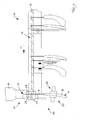
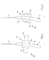
- FIG. 1 shows a schematic side view of a torque-testing device 10 according to the invention for a suspension hook H of a hanger K.
- the test apparatus 10 comprises a conveying device 11 in the form of a rotationally driven, rod-shaped transport spindle 12, which is oriented substantially horizontally and in discontinuous sequence Variety of hangers K of different design are hung, as is in FIG. 1 is indicated.
- the transport spindle 12 By rotation of the transport spindle 12, the hangers K in the transport direction T, ie according to FIG. 1 be transported from right to left in a hanging orientation.
- a test station 20 is arranged, which has a hook stop 17, against which the hanger K to be checked runs up with its suspension hook H.
- a separation station 14 for separating the test station 20 supplied hanger K provided.
- the separating station 14 comprises two bolt-like stops 15 and 16, which can be extended transversely to the transport direction T in the transport path of the hangers K in the region of the lower ends of the respective suspension hook H and withdrawn from the transport path.
- a pre-separating station 13 In the transport direction T before the separating station 14, i. upstream of the separating station 14, a pre-separating station 13 is provided, which has a further adjustable stop pin 13a, which is selectively introduced into the transport path of the hanger K and retractable from this.
- FIG. 12 attaches the suspension hook H of the hanger K with its upper curved portion to the hook stopper 17 while it is still suspended on the transport spindle 12 of the conveyor 11.
- a sensor device 31 is integrated, which detects the presence of a hanger K and its correct positioning.
- the sensor device 31 has two magnets 18 arranged laterally next to each other in the transverse direction to the transport direction T, which engage and attract the upper curved portion of the suspension hook H of the hanger K.
- a contact 32 of a circuit is integrated in each magnet 18, a contact 32 of a circuit is integrated. As soon as the metal suspension hook H bears against the magnet 18 and thus with the contacts 32, the circuit is closed, which is detected in a manner not shown. In this way it is ensured that when closing the circuit both a hanger K is present and positioned correctly.
- a test head 21 is arranged in the test station 20, which has a test clip 22 with two relatively mutually pivotable clip legs 23, as indicated by the arrows Z in FIG. 1 is indicated.
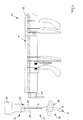
- the clip legs 23 can clamp the suspension hook H, which bears against the hook stop 17, between them (see FIG FIG. 2 ), wherein the hook stop 17 is encompassed by the clip legs 23 and thus the hanging hook H initially in its resting on the hook stop 17, held by the magnets 18 position remains.
- the test head 21 further comprises a bidirectional rotary drive 24, by means of which the test clip 22 is rotatable about a vertical axis V in both directions of rotation.
- a predetermined torque can be applied to the suspension hook H via the test clip 22, with the resulting movements being detected and evaluated via an evaluation unit 30 that is shown only schematically.
- a holding device 25 is arranged in the test station 20, which has two retaining clips 28, each comprising a base part 26 and two support legs 27 pivotally mounted thereto. Each retaining clip 28 can engage with a hanger body B of the hanger K on opposite sides of the hanger hook and thus fix the hanger K (see FIGS. 9, 10 and 11 ).
- the hanger K is fed by means of the conveyor 11 of the test station 20 and lays down with its hook H to the hook stop 17 and is held there by the magnets 18 in a predetermined position.
- the separating station 14 and the pre-separating station 13 prevent subsequent hangers interfere with the review.
- the test clip 22 of the probe 21 is still in the open position and also the retaining clips 28 of the holding device 25 are still open. This condition is in FIG. 1 shown.
- test clip 22 is closed, so that the clip legs 23 clamp the suspension hook H between them.
- This condition is in FIG. 2 shown.
- the suspension hook H initially bears against the magnet 18 of the hook stop 17.
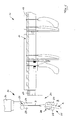
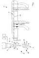
- the hook stop 17 is moved downward (see arrow R in FIG. 3 ), so that the test station 20 can be moved laterally in the transport direction T (see arrow H in FIG. 3 ) and the hanger K passes over the lowered hook stop 17, so that the hanger K is completely released from the hook stop 17, as shown in FIG FIG. 4 is shown. Then, the retaining clips 28 of the holding device 25 are closed and detect the hanger body B of the hanger K (s. FIG. 5 ).
- a predetermined torque is applied to the suspension hook H in both directions of rotation, as in FIG. 6 indicated by the double arrow D.
- the rotary drive 24 first brings the predetermined torque in a first rotational direction D1 (see FIG. 11 ) on the test bracket 22 on the suspension hook H, wherein the hanger is firmly clamped on the two retaining clips 28 of the holding device 25 on the hanger body B. Subsequently, a predetermined torque is applied in the other rotational direction D2 via the rotary drive 24.
- the hanger K of the evaluation unit 30 If the attachment of the suspension hook H in the hanger body B of the hanger K can absorb the torque, so that except elastic deformations no significant relative rotation between the hanger body B and the suspension hook H occur, the hanger K of the evaluation unit 30 as a reusable "Gutbügel "classified. Otherwise, the hanger K is classified as a "bad hanger".
- the test head 21 moves with the holding device 25 and the fixed clothes hanger K to a further transport device 29 (see FIG. Figure 7 ), on which the hanger K is hung with its suspension hook H.
- the further transport device 29 has a switch, which is controlled by the evaluation unit 30. If the hanger K is classified as a "gutter”, the switch is set so that the hanger K is transported to another workstation, such as a sorting station or a packing station. If the hanger K is classified as a "bad hanger", the switch is set so that the hanger is sorted out or one Processing station or a destruction station, for example, a shredder is supplied.
- both the test clip 22 of the probe 21 and the retaining clips 28 of the holding device 25 are opened, so that the hanger K released is transported and either due to its own weight and / or by motor drive along the secondary transport device 29 (see arrow S in FIG. 8 ). This concludes the inspection and classification of the hanger with regard to the torsional strength of its suspension hook.
Landscapes
- Physics & Mathematics (AREA)
- General Physics & Mathematics (AREA)
- Engineering & Computer Science (AREA)
- Mechanical Engineering (AREA)
- Chemical & Material Sciences (AREA)
- Analytical Chemistry (AREA)
- Chain Conveyers (AREA)
- Holders For Apparel And Elements Relating To Apparel (AREA)
Applications Claiming Priority (1)
| Application Number | Priority Date | Filing Date | Title |
|---|---|---|---|
| DE102008008992A DE102008008992A1 (de) | 2008-02-13 | 2008-02-13 | Drehmoment-Prüfvorrichtung für einen Aufhängehaken eines Kleiderbügels |
Publications (3)
| Publication Number | Publication Date |
|---|---|
| EP2090876A2 true EP2090876A2 (fr) | 2009-08-19 |
| EP2090876A3 EP2090876A3 (fr) | 2010-07-28 |
| EP2090876B1 EP2090876B1 (fr) | 2011-08-03 |
Family
ID=40626857
Family Applications (1)
| Application Number | Title | Priority Date | Filing Date |
|---|---|---|---|
| EP09001802A Not-in-force EP2090876B1 (fr) | 2008-02-13 | 2009-02-10 | Dispositif d'essai d'un crochet de suspension d'un cintre pour vêtements par application de couple |
Country Status (3)
| Country | Link |
|---|---|
| EP (1) | EP2090876B1 (fr) |
| AT (1) | ATE519102T1 (fr) |
| DE (1) | DE102008008992A1 (fr) |
Cited By (1)
| Publication number | Priority date | Publication date | Assignee | Title |
|---|---|---|---|---|
| CN104655411A (zh) * | 2015-01-27 | 2015-05-27 | 常州工学院 | 一种折叠式晾衣架和升降式晾衣架的寿命检测装置 |
Family Cites Families (17)
| Publication number | Priority date | Publication date | Assignee | Title |
|---|---|---|---|---|
| DE2731090C2 (de) * | 1977-07-09 | 1983-09-15 | Nagel, Peter, 7442 Neuffen | Drehmoment-Schrauber |
| SE412647B (sv) * | 1977-10-07 | 1980-03-10 | Atlas Copco Ab | Sett och anordning for overvakning och styrning av skruvforbandsatdragning |
| DE8228473U1 (de) * | 1982-10-09 | 1983-06-23 | Herbert Kannegiesser Gmbh + Co, 4973 Vlotho | Foerdervorrichtung fuer be- und nicht beladene kleiderbuegel |
| DD260329A1 (de) * | 1987-05-07 | 1988-09-21 | Moeve Werk Muehlhausen Veb | Pruefvorrichtung zur ermittlung der torsionsmomentenkennlinie von torsionselementen, insbesondere elemente hoher elastizitaet |
| DE4026546A1 (de) * | 1989-08-24 | 1991-02-28 | Japan Steel Co | Transportsystem |
| DE4025430A1 (de) * | 1990-08-10 | 1992-02-13 | Psm Drucklufttechnik Vertrieb | Drehschrauberkopf |
| DE4205456A1 (de) * | 1992-02-22 | 1993-08-26 | Psb Foerderanlagen | Schneckenfoerderer |
| GB2273776A (en) * | 1992-12-24 | 1994-06-29 | Crane Electronics | Angular motion detector for a torque wrench |
| DE29505986U1 (de) * | 1995-04-06 | 1995-06-01 | RSL Logistik GmbH & Co., 86899 Landsberg | Vorrichtung zum Lösen verhedderter Haken |
| AUPN657995A0 (en) * | 1995-11-15 | 1995-12-07 | Rosebay Terrace Pty Ltd | Automated sorting apparatus and system |
| DE29614237U1 (de) * | 1996-08-16 | 1997-12-18 | Karner & Co GmbH, 97737 Gemünden | Kleider- und Wäschebügel |
| DE29813739U1 (de) * | 1998-07-31 | 1999-12-09 | MAWA Metallwarenfabrik Wagner GmbH, 85276 Pfaffenhofen | Transportbügel |
| ATE508668T1 (de) * | 1999-09-23 | 2011-05-15 | Coronet Kleiderbuegel & Logistik Gmbh | Warenträger, insbesondere kleiderbügel |
| DE20020892U1 (de) * | 1999-12-06 | 2001-03-08 | Braitrim Deutschland GmbH, 32657 Lemgo | Kleiderbügel |
| DE10217283B4 (de) * | 2002-04-12 | 2005-10-13 | Fraunhofer-Gesellschaft zur Förderung der angewandten Forschung e.V. | Vorrichtung zum Einstellen und Prüfen der Spannkraft von Schraubverbindungen |
| DE10217416C1 (de) * | 2002-04-18 | 2003-07-31 | Ivo Geilenbruegge | Drehmomentmessvorrichtung |
| US20060162285A1 (en) * | 2005-01-21 | 2006-07-27 | Haynes Clinton A | Torque transducer assembly |
-
2008
- 2008-02-13 DE DE102008008992A patent/DE102008008992A1/de not_active Withdrawn
-
2009
- 2009-02-10 EP EP09001802A patent/EP2090876B1/fr not_active Not-in-force
- 2009-02-10 AT AT09001802T patent/ATE519102T1/de active
Cited By (1)
| Publication number | Priority date | Publication date | Assignee | Title |
|---|---|---|---|---|
| CN104655411A (zh) * | 2015-01-27 | 2015-05-27 | 常州工学院 | 一种折叠式晾衣架和升降式晾衣架的寿命检测装置 |
Also Published As
| Publication number | Publication date |
|---|---|
| EP2090876B1 (fr) | 2011-08-03 |
| DE102008008992A1 (de) | 2009-08-20 |
| EP2090876A3 (fr) | 2010-07-28 |
| ATE519102T1 (de) | 2011-08-15 |
Similar Documents
| Publication | Publication Date | Title |
|---|---|---|
| DE68925787T2 (de) | Verfahren und Vorrichtung zum Ausbreiten von Gewebestücken | |
| EP0214461B1 (fr) | Dispositif pour enlever la feuille de protection d'un circuit imprimé recouvert d'une couche photorésistante exposée | |
| EP3154863B1 (fr) | Procédé et dispositif de traitement d'un contenant de transport d'objets de valeur | |
| DE102014203298A1 (de) | Hängefördereinrichtung mit Ladestation | |
| DE3725523C1 (fr) | ||
| AT508159A4 (de) | Fehlerstellenerkennung | |
| EP2199219B1 (fr) | Dispositif de serrage et utilisation d'un dispositif de serrage pour l'étiquetage d'objets, procédé d'étiquetage d'objets | |
| WO2013034255A2 (fr) | Procédé pour déterminer la présence de caractéristiques prédéfinies d'un produit composé de contenants et dispositif pour la mise en oeuvre dudit procédé | |
| EP2090876B1 (fr) | Dispositif d'essai d'un crochet de suspension d'un cintre pour vêtements par application de couple | |
| DE3737484C2 (de) | Steuereinrichtung an einer Verpackungsmaschine für Bekleidungsstücke | |
| DE102015106759B4 (de) | Packvorrichtung zum Verpacken von Behältern in eine Verpackungseinheit mit einem Gefache | |
| DE69616215T2 (de) | Verfahren zur Bearbeitung von Fadenresten | |
| CH686953A5 (de) | Verfahren und Vorrichtung zum Beschicken und Entnehmen von mit einer Materialbahn bewickelten Rollen in einer Maschine zum Verarbeiten der Materialbahn, insbesondere einer Druckmaschine. | |
| DE102007030382A1 (de) | Verfahren und Vorrichtung zum Verschweißen von Säcken | |
| DE69922469T2 (de) | Vorrichtung und Verfahren zum Entfernen einer Stange von mehreren Stangen | |
| WO2012139809A1 (fr) | Dispositif destiné au contrôle de produits pharmaceutiques | |
| DE19505474C2 (de) | Verfahren und Vorrichtung zum Prüfen von Flaschen aus Kunststoff auf Kontaminationen | |
| DE3007540C2 (de) | Vorrichtung zum Prüfen und Aussortieren von Flaschen in einer Flaschenbehandlungsanlage | |
| EP1364899A1 (fr) | Méthode pour transporter des produits plats et flexibles, et dispositif pour mettre en oeuvre la méthode | |
| EP0278909B1 (fr) | Méthode et dispositif pour isoler, manipuler et réexpédier des conteneurs | |
| DE69406822T2 (de) | Einrichtung zur Probeentnahme von flachen Produkten, die von einer Förderanlage getragen werden | |
| DE102018009417B4 (de) | Vorrichtung und Verfahren zur Faltung und Bevorratung von Buchdokumenten | |
| DE202014105220U1 (de) | Wurstaufhängeelement und Vorrichtung zum Aufhängen von Wurst von einer Stange auf einem Aufhängeelement | |
| EP1667913A1 (fr) | Procede pour remplir des sacs | |
| DE2722417A1 (de) | Vorrichtung zum zufuehren, ausrichten, sortieren von laenglichen werkstuecken |
Legal Events
| Date | Code | Title | Description |
|---|---|---|---|
| PUAI | Public reference made under article 153(3) epc to a published international application that has entered the european phase |
Free format text: ORIGINAL CODE: 0009012 |
|
| AK | Designated contracting states |
Kind code of ref document: A2 Designated state(s): AT BE BG CH CY CZ DE DK EE ES FI FR GB GR HR HU IE IS IT LI LT LU LV MC MK MT NL NO PL PT RO SE SI SK TR |
|
| AX | Request for extension of the european patent |
Extension state: AL BA RS |
|
| PUAL | Search report despatched |
Free format text: ORIGINAL CODE: 0009013 |
|
| AK | Designated contracting states |
Kind code of ref document: A3 Designated state(s): AT BE BG CH CY CZ DE DK EE ES FI FR GB GR HR HU IE IS IT LI LT LU LV MC MK MT NL NO PL PT RO SE SI SK TR |
|
| AX | Request for extension of the european patent |
Extension state: AL BA RS |
|
| RIC1 | Information provided on ipc code assigned before grant |
Ipc: G01M 19/00 20060101AFI20090518BHEP Ipc: B65G 33/00 20060101ALI20100623BHEP |
|
| REG | Reference to a national code |
Ref country code: DE Ref legal event code: R079 Ref document number: 502009001011 Country of ref document: DE Free format text: PREVIOUS MAIN CLASS: G01M0019000000 Ipc: G01M0099000000 |
|
| 17P | Request for examination filed |
Effective date: 20110125 |
|
| RIC1 | Information provided on ipc code assigned before grant |
Ipc: G01M 99/00 20110101AFI20110223BHEP Ipc: B65G 33/00 20060101ALI20110223BHEP |
|
| AKX | Designation fees paid |
Designated state(s): AT BE CH DE FR LI NL |
|
| GRAP | Despatch of communication of intention to grant a patent |
Free format text: ORIGINAL CODE: EPIDOSNIGR1 |
|
| GRAS | Grant fee paid |
Free format text: ORIGINAL CODE: EPIDOSNIGR3 |
|
| GRAA | (expected) grant |
Free format text: ORIGINAL CODE: 0009210 |
|
| AK | Designated contracting states |
Kind code of ref document: B1 Designated state(s): AT BE CH DE FR LI NL |
|
| REG | Reference to a national code |
Ref country code: CH Ref legal event code: EP |
|
| REG | Reference to a national code |
Ref country code: DE Ref legal event code: R096 Ref document number: 502009001011 Country of ref document: DE Effective date: 20110929 |
|
| REG | Reference to a national code |
Ref country code: NL Ref legal event code: T3 |
|
| PLBE | No opposition filed within time limit |
Free format text: ORIGINAL CODE: 0009261 |
|
| STAA | Information on the status of an ep patent application or granted ep patent |
Free format text: STATUS: NO OPPOSITION FILED WITHIN TIME LIMIT |
|
| 26N | No opposition filed |
Effective date: 20120504 |
|
| REG | Reference to a national code |
Ref country code: DE Ref legal event code: R097 Ref document number: 502009001011 Country of ref document: DE Effective date: 20120504 |
|
| REG | Reference to a national code |
Ref country code: FR Ref legal event code: ST Effective date: 20121031 |
|
| PG25 | Lapsed in a contracting state [announced via postgrant information from national office to epo] |
Ref country code: FR Free format text: LAPSE BECAUSE OF NON-PAYMENT OF DUE FEES Effective date: 20120229 |
|
| REG | Reference to a national code |
Ref country code: CH Ref legal event code: PL |
|
| PG25 | Lapsed in a contracting state [announced via postgrant information from national office to epo] |
Ref country code: LI Free format text: LAPSE BECAUSE OF NON-PAYMENT OF DUE FEES Effective date: 20130228 Ref country code: CH Free format text: LAPSE BECAUSE OF NON-PAYMENT OF DUE FEES Effective date: 20130228 |
|
| PGFP | Annual fee paid to national office [announced via postgrant information from national office to epo] |
Ref country code: NL Payment date: 20180221 Year of fee payment: 10 |
|
| PGFP | Annual fee paid to national office [announced via postgrant information from national office to epo] |
Ref country code: DE Payment date: 20180221 Year of fee payment: 10 |
|
| PGFP | Annual fee paid to national office [announced via postgrant information from national office to epo] |
Ref country code: AT Payment date: 20180220 Year of fee payment: 10 Ref country code: BE Payment date: 20180221 Year of fee payment: 10 |
|
| REG | Reference to a national code |
Ref country code: DE Ref legal event code: R119 Ref document number: 502009001011 Country of ref document: DE |
|
| REG | Reference to a national code |
Ref country code: NL Ref legal event code: MM Effective date: 20190301 |
|
| REG | Reference to a national code |
Ref country code: AT Ref legal event code: MM01 Ref document number: 519102 Country of ref document: AT Kind code of ref document: T Effective date: 20190210 |
|
| REG | Reference to a national code |
Ref country code: BE Ref legal event code: MM Effective date: 20190228 |
|
| PG25 | Lapsed in a contracting state [announced via postgrant information from national office to epo] |
Ref country code: AT Free format text: LAPSE BECAUSE OF NON-PAYMENT OF DUE FEES Effective date: 20190210 |
|
| PG25 | Lapsed in a contracting state [announced via postgrant information from national office to epo] |
Ref country code: NL Free format text: LAPSE BECAUSE OF NON-PAYMENT OF DUE FEES Effective date: 20190301 Ref country code: DE Free format text: LAPSE BECAUSE OF NON-PAYMENT OF DUE FEES Effective date: 20190903 |
|
| PG25 | Lapsed in a contracting state [announced via postgrant information from national office to epo] |
Ref country code: BE Free format text: LAPSE BECAUSE OF NON-PAYMENT OF DUE FEES Effective date: 20190228 |