EP2090919B1 - Signalverarbeitungssystem - Google Patents
Signalverarbeitungssystem Download PDFInfo
- Publication number
- EP2090919B1 EP2090919B1 EP09000681.8A EP09000681A EP2090919B1 EP 2090919 B1 EP2090919 B1 EP 2090919B1 EP 09000681 A EP09000681 A EP 09000681A EP 2090919 B1 EP2090919 B1 EP 2090919B1
- Authority
- EP
- European Patent Office
- Prior art keywords
- section
- endoscope
- log data
- setting
- user
- Prior art date
- Legal status (The legal status is an assumption and is not a legal conclusion. Google has not performed a legal analysis and makes no representation as to the accuracy of the status listed.)
- Not-in-force
Links
Images









Classifications
-
- G—PHYSICS
- G02—OPTICS
- G02B—OPTICAL ELEMENTS, SYSTEMS OR APPARATUS
- G02B23/00—Telescopes, e.g. binoculars; Periscopes; Instruments for viewing the inside of hollow bodies; Viewfinders; Optical aiming or sighting devices
- G02B23/24—Instruments or systems for viewing the inside of hollow bodies, e.g. fibrescopes
- G02B23/2476—Non-optical details, e.g. housings, mountings, supports
- G02B23/2484—Arrangements in relation to a camera or imaging device
Definitions
- Endoscopes are widely used in medical and industrial fields. Recent years have seen wide use of endoscope apparatuses that include an endoscope equipped with an external television camera, which is constructed by attaching a television camera having image pickup means to the eye cup of the optical endoscope, or include an electronic endoscope having image pickup means built in the distal end portion of the endoscope, and display an image captured by the endoscope on the monitor to enable the user to perform observation and treatment while viewing the displayed image.
- endoscope apparatuses employ a light source apparatus for supplying illumination light to the endoscope, a camera control unit (also referred to as "video processor") including an image signal processing circuit for displaying an endoscopic image, a TV monitor for displaying the endoscopic image, as well as a plurality of peripheral apparatuses such as, e.g., an insufflation apparatus and high frequency cauterization apparatus.
- a light source apparatus for supplying illumination light to the endoscope
- a camera control unit also referred to as "video processor”
- peripheral apparatuses such as, e.g., an insufflation apparatus and high frequency cauterization apparatus.
- the plurality of peripheral apparatuses are typically connected to a system controller for concentrated control.
- the peripheral apparatuses of the endoscope system are equipped with electronic instruments such as an image pickup device and image processing means, precise mechanisms such as filter drive mechanism for sequentially irradiating light beams of RGB three colors, and consumable items such as a light source lamp, etc. Therefore the peripheral apparatuses normally require periodical maintenance by maintenance workers having related expertise.
- a single maintenance worker is in charge of maintaining a plurality of electronic endoscopes and the endoscope processors.
- the maintenance worker carries out the work of maintaining electronic endoscopes and endoscope processors that are remotely located. This situation has caused problems including high maintenance cost and inability to quickly address abnormalities that the electronic endoscopes and endoscope processor may have.
- Japanese Patent Application Laid-Open Publication No. 2002-263063 discloses an endoscope system that allows the maintenance work to be quickly conducted even at a remote location, employing a technique which allows a remotely located service server to monitor endoscope processors installed in a plurality of facilities and instruments connected to the endoscope processors.
- Japanese Patent Application Laid-Open Publication No. 2005-111080 proposes a surgery support system that during surgery constantly maintains the settings of instruments in the surgery room at appropriate states, thus enabling it to remotely provide an appropriate surgery support.
- the image color tone may be changed by switching of observation modes (normal light, NBI, AFI) or change of color tone by user operation.
- observation modes normal light, NBI, AFI
- an unintended user operation may erroneously change the image color tone, making the user have a sense of incongruity on the resulting image.
- a user having a sense of incongruity on (the color tone of) the observation image, may not be able to identify whether the incongruity is due to an instrument abnormality or simply a setting changing operation not intended by the user.
- This situation deprives the user of an appropriate field service (e.g., a service man may be sent to check the instruments even if the instruments are not abnormal), disabling the user to use the instruments during the instrument checking and waiting time.
- the inspection efficiency is thus problematically decreased.
- the present invention has been made in view of the above circumstances and has its object to provide an endoscope system that allows the user to take appropriate measures by monitoring whether the image deficiency is due to an instrument abnormality or whether the image merely appears deficient due to a setting change operation not intended by the user.
- a signal processing system comprises an endoscope for picking up an image of an inner body cavity by an image-pickup section; a light source for supplying illumination light to the endoscope; and a signal processing device including a plurality of signal processing sections for processing image-pickup signals from the endoscope, wherein the signal processing device includes: a control section for controlling, based on a setting value, operation of at least one of an internal circuit of the endoscope, an internal circuit of the signal processing section, and an internal circuit of the light source; a setting value changing section for changing the setting value; a log recording section for recording change history of the setting value as log data; a data sending section for sending the log data to an external instrument via a network; and a command receiving section for receiving a control command which is based on the log data from the external instrument via the network.
- control section controls the setting value changing section based on the control command receivedid from the external instrument.
- a support facility for remotely supporting an operation of a user system, including the signal processing system according to first and second aspect of the invention as described above.
- the support facility comprises a log data receiving section for receiving, via a network, setting state log data, for example from the log data sending section of the signal processing system according to the first and second aspect described above; a log data analyzing section for analyzing the received setting state log data; and a restore command sending section for sending a restore command which is based on an analysis result of the log data analyzing section, for example to a restoration operation activating section of the signal processing system according to the first or second aspect described above.
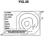
- FIGS. 1 to 26 relate to a first embodiment of the present invention.
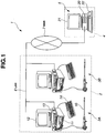
- FIG. 1 is a configuration diagram showing a configuration of an endoscope system.
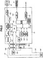
- FIG. 2 is a block diagram showing a configuration of a CCU of FIG. 1 .
- FIG. 3 is a view showing a configuration of an operation panel of FIG. 2 .
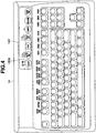
- FIG. 4 is a view showing a configuration of a keyboard of FIG. 2 .
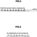
- FIG. 5 is a view showing a data format configuration of operation log data to be stored in a log memory of FIG. 2 .
- FIG. 6 is a first view showing a specific data configuration of the data format configuration of FIG. 5 .
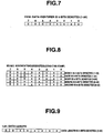
- FIG. 7 is a second view showing a specific data configuration of the data format configuration of FIG. 5 .
- FIG. 1 is a configuration diagram showing a configuration of an endoscope system.
- FIG. 2 is a block diagram showing a configuration of a CCU of FIG. 1 .
- FIG. 3 is a view showing a
- FIG. 8 is a third view showing a specific data configuration of the data format configuration of FIG. 5 .
- FIG. 9 is a fourth view showing a specific data configuration of the data format configuration of FIG. 5 .
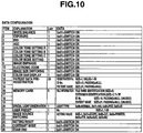
- FIG. 10 is a fifth view showing a specific data configuration of the data format configuration of FIG. 5 .
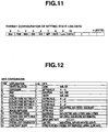
- FIG. 11 is a view showing a data format configuration of setting state log data to be stored in the log memory of FIG. 2 .
- FIG. 12 is a view showing a specific data configuration of the data format configuration of FIG. 11 .
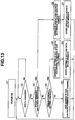
- FIG. 13 is a flow chart showing a flow of a processing for storing of system log data in the CCU of FIG. 2 .
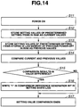
- FIG. 14 is a flow chart showing a flow of a processing for checking the setting state of the system log data.
- FIG. 14 is a flow chart showing a flow of a processing for checking the setting state of the system log data.
- FIG. 15 is a function block diagram showing a function of the endoscope system of FIG. 1 .
- FIG. 16 is a function block diagram showing a function of a log data analyzing section of FIG. 15 .
- FIG. 17 is a view showing a data format configuration of a restore command generated by a log data analyzing section of FIG. 16 .
- FIG. 18 is a view showing a data configuration of a command body CMD of the restore command of FIG. 17 .
- FIG. 19 is a view illustrating the content of the restore command of FIG. 17 .
- FIG. 20 is a view illustrating operation transition of the endoscope system of FIG. 1 .
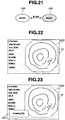
- FIG. 21 is a view illustrating a manner of indication of a setting switch in the operation transition of FIG. 20 .
- an endoscope system 1 of this embodiment includes: a plurality of endoscope apparatuses 3A, 3B each serving as a signal processing system, which are provided in a medical facility 2 which is a user system; and a support system 5 provided in a support facility 4 which is a remote operation system located away from the medical facility 2.
- the plurality of endoscope apparatuses 3A, 3B and the support system 5 are communicatably connected to each other via LAN (Local Area Network) 6 and WAN (Wide Area Network) 7.
- the endoscope apparatus 3A includes an endoscope 10 for picking up images of an intra-body cavity observation region; a light source apparatus 11 for supplying illumination light to the endoscope 10; and a camera control unit (hereinafter "CCU") 13 for displaying an observation region image picked up by the endoscope 10 on a monitor 12 as an endoscopic image.
- the CCU 13 is connected with a keyboard 14 which is used to input data.
- the endoscope apparatus 3B also has the same configuration as the endoscope apparatus 3A.
- the CCU 13 is detachably connectable via a connector 131 a with a connector 105 of the endoscope 10.
- the endoscope 10 has an insertion portion 101 to be inserted into the body cavity.
- a scope CCD 102 for image pick-up of the observation region
- a switch 103 for instructing various operations (such as bending operation and release operation) which is provided on an operation portion at a proximal end of the insertion portion 101
- a scope CPU 104 for controlling each part of the endoscope 10 and managing endoscope type information, etc., which is provided in the operation portion at the proximal end of the insertion portion 101.
- the CCU 13 includes a preprocess section 131 which is inputted with an image-pickup signal from the scope CCD 102 of the endoscope 10 via the connectors 105 and 131a.
- the preprocess section 131 is a processing section for executing known analogue processings including noise removal processing, correlative double sampling processing, and white balance processing, on the image-pickup signal from the scope CCD 102.
- the digital video signal processing section 133 executes known image (video) digital processings (such as color tone correction, ⁇ correction, and expansion/reduction processing) on the digital signal from the A/D conversion section 132 using a VRAM 135, etc.
- the digitally processed digital video signal is converted to an analogue signal by a D/A conversion section 134. This converted analogue signal is displayed on the monitor 12 as an endoscopic image.
- the CCU 13 further includes a CPU 136.
- the CPU 136 sends/receives data to/from the scope CPU 104 and receives inputs of instruction signals from the switch 103 of the endoscope via the connectors 105 and 131.
- the CPU 136 is further connected to the keyboard 14 via a PCI bus bridge 143 and a USB controller 144.
- the CPU 136 can thus receive information inputted using the keyboard 14 and have various information displayed on the keyboard 14.
- the CCU 13 is furthermore connected to the LAN 6 (see FIG. 1 ) via the PCI bus bridge 143 and an Ethernet (registered trademark) controller 145.
- the CPU 136 is also connected to an SDRAM 139, FLASH ROM 140, log memory 141 and compand processing section 142 via the internal bus.
- the CPU 136 controls, e.g., the compand processing section 142 using the SDRAM 139, performs a compand processing on the digital image processed by the digital video signal processing section 133, and records the resultant image into the FLASH ROM 140.
- the CPU 136 moreover saves and manages in the log memory 141, as system log data, history information (log data) on settings and operations made with the operation panel 138, the keyboard 14, etc.; information on various settings/operations of the endoscope 10 (acquired from the scope CPU 104 of the endoscope 10); or information on various settings/operations of the light source apparatus 11, which is produced in various processings in parts of the CCU 13.
- system log data has generally been stored and saved in the log memory 141 to be used by the CPU 136 to manage the system settings when activating the endoscope apparatus, as well as by the user to use the inspection flow as data for checking the executed procedures and for education after completion of an inspection with the endoscope apparatus.
- the keyboard 14 includes above a normal (known) key input portion, a display panel portion 14A on which various states can be directly inputted and displayed.
- the setting state of the display panel portion 14A is sent to the CPU 136 via the USB controller 144.
- the manner of indication of the mode switch 150a on the display panel portion 14A is controllable by the CPU 136 via the USB controller 144, as the manner of indication of the operation panel 138 is.
- the system log data includes operation log data and setting state log data.
- the CPU 136 stores the operation log data and setting state log data in a predetermined area of the log memory 141.
- the operation log data has a data format configuration as shown in FIG. 5 , including Stx, Item, MO, DD, HH, MT, SEC, Len and Data.
- Stx is header data as shown in FIG. 6 .
- Item is data extension (see FIG. 10 ) for identifying data classification (setting/operation classification) as shown in FIG. 7 .
- MO month
- DD date
- HH hour
- MT minute
- SEC second
- Len shows the data length of the operation log data as shown in FIG. 9 .
- Data is the data body of the operation log data, having a data configuration which is classified by Item (extension), as shown in FIG. 10 .
- the setting state log data also includes Stx, Item, MO, DD, HH, MT, SEC, Len and Data, as shown in FIG. 11 .
- Data configuration of Stx, Item, MO, DD, HH, MT, SEC and Len is the same as of the operation log data.
- Data is the data body of the setting state log data, having a data configuration which is classified by Item (extension) as shown in FIG. 12 .
- step S2 the CPU 136 of the CCU 13 checks whether or not the setting state of each part of the endoscope apparatus has been changed.
- step S3 the CPU 136 determines whether or not the state change is based on a predetermined function operation executed by the user. If the determination results in "No”, then the process proceeds to step S4.
- step S6 the CPU 136 newly generates operation log data according to the operation log data format (see FIG. 5 ) of the system log data.
- step S7 the newly generated operation log data is stored in a predetermined area of the log memory 141. The process then returns to step S2.
- step S8 the CCU 13 newly generates setting state log data according to the setting state log data format (see FIG. 11 ) of the system log data.
- step S9 the newly generated setting state log data is stored in a predetermined area of the log memory 141. The process then returns to step S2.
- the CPU 136 stores each of actual setting values made last into the FLASH ROM 140 before completing the processing.
- step S12 the CPU 136 stores setting values of setting items stored in the FLASH ROM 140 (setting values of previous settings made last) into the SDRAM 139 as current values.
- step S13 the CPU 136 stores setting values of setting items of the setting state log data (last setting values in operational history) stored in the log memory 141, into the SDRAM 139 as previous values.
- step S14 the CPU 136 compares the current and previous values.
- step S15 the CPU 136 determines if the comparison results in any difference between the current and previous values. If the result is "No", then the process proceeds to step S17.
- step S15 determines the result is "Yes”
- step S16 the CPU 136 writes "1" into a comparison difference generation bit in the setting state log data of the system log data (by default, the comparison difference generation bit is set to "0").
- step S 17 the setting value comparison completes, completing the check-processing.
- this check-processing allows the setting state log data to have information of the comparison difference generation bit, in addition to the data shown in FIG. 5 .
- the endoscope system 1 of this embodiment includes two mechanism blocks as system functions: the user system (the medical facility 2) and the remote operation system (the support facility 4).
- the user system (the medical facility 2) includes: a log data read-out section 181 for reading out the setting state log data stored in the log memory 141; a log data sending section 182 for sending the setting state log data which is read out to the support system 5 of the remote operation system (the support facility 4); and a restoration operation activating section 183 for receiving a restore command from the support system 5 of the remote operation system (the support facility 4) and activating a restoration operation.
- the restoration operation by the restoration operation activating section 183 will be detailed later.
- the log data read-out section 181, the log data sending section 182, and the restoration operation activating section 183 are realized in a software manner by a program executed by the CPU 136.
- the remote operation system (the support facility 4) includes: a log data receiving section 202 for receiving the setting state log data from the log data sending section 182 of the user system (the medical facility 2); a log data analyzing section 203 for analyzing the received setting state log data; a communication requesting section 201 for requesting the log data read-out section 181 of the user system (the medical facility 2) to send the setting state log data, based on the control by the log data analyzing section 203; and a restore command sending section 204 for sending the restore command which is based on the analysis result of the log data analyzing section 203 to the restoration operation activating section 183 of the user system (the medical facility 2).
- the communication requesting section 201, the log data receiving section 202, the log data analyzing section 203, and the restore command sending section 204 are realized in a software manner by a program executed by a CPU (not shown) of the support system 5.
- the log data analyzing section 203 includes a log data displaying section 211 for displaying the setting state log data on the monitor 21, and a restore command generating/outputting section 212 for generating and outputting a restore command based on input from the keyboard 22.
- An LED control instruction command as an exemplary restore command has a data format configuration including Stx and CMD, as shown in FIG. 17 .
- Stx is header data (see FIG. 6 ).
- CMD is 1-byte data as shown in FIG. 18 and is accordingly represented as the commands as shown in FIG. 19 .
- the user system On receiving the LED control instruction command, the user system (the medical facility 2), i.e., the CPU 136, performs, e.g., turn-on control of the LED in the mode switch 150 on the operation panel 138.
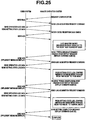
- FIG. 20 an operational transition of the endoscope system of this embodiment based on a specific restore command is described. If an instrument setting is abnormal (in abnormal state) at the time of inspection, the user attempts to restore the instrument setting. However, the wide variety of setting items and the user engagement with the inspection disables the user to allot any time to analyze the setting abnormality. To counter such disability, the user system requests the remote operation system to analyze the setting abnormality. In response the remote operation system starts analyzing this abnormality using the setting state log data.
- Conceivable instrument abnormality states include those due to simple erroneous setting by the user, unsuitable setting for the observation mode, and abnormal instrument device.
- the remote operation system analyzes these abnormality states using the setting state log data.
- the remote operation system (the support facility 4) requests communication to the user system (the medical facility 2).
- the user system sends "Redy" to the remote operation system to establish communication between the user system and the remote operation system.
- the remote operation system On confirming the established communication, the remote operation system sends to the user system a log acquisition request command which requests the setting state log data. On receiving the log acquisition request command, the user system sends the setting state log data to the remote operation system according to the request.
- the remote operation system checks the received setting state log data by, e.g., check sum, etc., and sends an "OK" command which indicates normal reception to the user system. Upon receiving the "OK” command, the user system returns "ACK" to the remote operation system, thereby completing the sending/receiving of the setting state log data between the two systems.
- the remote operation system causes the setting state log data to be displayed on the monitor 21, which permits the maintenance worker operating the support system 5 to analyze the log data. For example, on finding that "the observation mode is set to "NBI mode” instead of the "normal observation mode” the user desires, then the maintenance worker inputs the analysis content using the keyboard 22.
- the support system 5 again generates, based on the inputted analysis content, a restore command, i.e., a command (0x0E for blinking the LED of the observation mode change-over switch of the LED control instruction command.
- the support system 5 then sends the generated command to the user system.
- the user system On receiving the LED control instruction command (command for blinking the LED of the observation mode change-over switch), the user system returns "ACK" to the remote operation system.
- the log data analyzing section 203 has a function configuration which is different from that in the first embodiment.
- the log data analyzing section 203 of this embodiment includes a data extracting section 213 for extracting setting state log data by comparison with a predetermined threshold value, as shown in FIG. 27 .
- the log data displaying section 211 displays the extraction result of the data extracting section 213 on the monitor 21 together with the setting state log data.
- the maintenance worker inputs to instruct the restore command generating/outputting section 212 to generate a reset command for instructing to reset the setting data, based on the extraction result of the data extracting section 213.
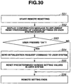
- the remote operation system starts a remote setting processing for the user system in step S31 by using the function of the log data analyzing section 203, as shown in FIG. 29 .
- step S39 the remote operation system confirms approval of the execution confirmation message from the user system. Having confirmed the approval from the user system, the remote operation system sends a setting resetting request command to the user system in step S40, and completes the remote setting processing in step S41.
- This embodiment can compare various setting values of the setting state log data with predetermined threshold values that correspond to, e.g., the observed situation for each observation mode and remotely reset the setting values that exceed the threshold values. Accordingly, this embodiment can, in addition to achieving the effect of the first embodiment, more easily and surely set the instrument into a state appropriate for the observed situation.
- this embodiment enables the user to check the settings and the like, through sound information and video information.
- the user is thus allowed to more easily monitor system instrument abnormalities and accordingly set the instrument into a state suitable for the observed situation than in the first embodiment.
Landscapes
- Physics & Mathematics (AREA)
- Engineering & Computer Science (AREA)
- Multimedia (AREA)
- Astronomy & Astrophysics (AREA)
- General Physics & Mathematics (AREA)
- Optics & Photonics (AREA)
- Endoscopes (AREA)
- Debugging And Monitoring (AREA)
- Instruments For Viewing The Inside Of Hollow Bodies (AREA)
Claims (9)
- Endoskopsystem (1), umfassend ein Benutzersystem (2) und ein Fernbedienungssystem (4), das umfasst:ein Endoskop (3A, 3B), das in dem Benutzersystem (2) bereitgestellt wird und konfiguriert ist, um anhand eines Bildaufnahmeteils (102) ein Bild einer Person in einer Körperhöhle aufzunehmen;einen Signalverarbeitungsteil (13), der in dem Benutzersystem (2) bereitgestellt wird und konfiguriert ist, um das Bild der Person auszugeben, das durch Verarbeiten von Bildaufnahmesignalen aus dem Endoskop (3A, 3B) erzielt wird;eine Lichtquelle (11), die in dem Benutzersystem (2) bereitgestellt wird und konfiguriert ist, um dem Endoskop (3A, 3B) Beleuchtungslicht zum Beleuchten der Person zuzuführen;einen Sollwertänderungsteil (138, 150; 14, 150a; 138, 300), der in dem Benutzersystem (2) bereitgestellt wird und konfiguriert ist, um eine Bedienung auszuführen, um einen Sollwert zu ändern, der mit der Bedienung mindestens eines von dem Endoskop (3A, 3B), dem Signalverarbeitungsteil (13) und der Lichtquelle (11) zusammenhängt;einen Steuerungsteil (136 bis 138, 150; 140, 136, 143, 144, 150a; 136 bis 138, 300), der konfiguriert ist, um das Endoskop (3A, 3B), den Signalverarbeitungsteil (13) und die Lichtquelle (11) basierend auf dem Sollwert, der gemäß der Bedienung des Sollwertänderungsteils (138, 150; 14, 150a; 138, 300) eingestellt ist, zu steuern;einen Protokollaufzeichnungsteil (141), der in dem Benutzersystem (2) bereitgestellt wird und konfiguriert ist, um einen Änderungsverlauf des Sollwerts als Sollzustandsprotokolldaten aufzuzeichnen;einen Datensendeteil (143, 145, 182, 202, 203), der in dem Benutzersystem (2) bereitgestellt wird und konfiguriert ist, um die Sollzustandsprotokolldaten über ein Netzwerk (6, 7) an das Fernbedienungssystem (4) zu senden; undeinen Befehlsempfangsteil (143, 145, 203, 204, 183), der konfiguriert ist, um einen Steuerungsbefehl, der auf den Sollzustandsprotokolldaten von dem Fernbedienungssystem (4) basiert, über das Netzwerk (6, 7) zu empfangen,dadurch gekennzeichnet, dassder Steuerungsteil (136 bis 138, 150; 14, 136, 143, 144, 150a; 136 bis 138, 300) geeignet ist, um den Sollwertänderungsteil (138, 150; 14, 150a; 138, 300) basierend auf dem Steuerungsbefehl, der von dem Fernbedienungssystem (4) empfangen wird, zu steuern, unddas Fernbedienungssystem (4) einen Teil (203) zum Analysieren von Protokolldaten umfasst, der konfiguriert ist, um die empfangenen Sollzustandsprotokolldaten zu analysieren und den Steuerungsbefehl zu generieren.
- Endoskopsystem (1) nach Anspruch 1,
wobei der Steuerungsteil geeignet ist, um in einem Speicher den Sollwert zu einem Zeitpunkt der Beendigung einer Inspektion in dem Benutzersystem (2) als einen aktuellen Wert zu speichern, um in dem Speicher einen letzten Sollwert in dem Änderungsverlauf, der in den Sollzustandsprotokolldaten aufgezeichnet ist, zu speichern, und um den aktuellen Wert und den zuvor in dem Speicher gespeicherten Wert zu vergleichen. - Endoskopsystem (1) nach Anspruch 2, wobei der Steuerungsteil geeignet ist, um eine Verarbeitung auszuführen, um in die Sollzustandsprotokolldaten Bitdaten zu schreiben, mit denen eine Bestimmung möglich ist, ob ein Unterschied zwischen dem aktuellen Wert und dem vorhergehenden Wert besteht, basierend auf einem Vergleichsergebnis des Vergleichs des aktuellen Wertes und des vorhergehenden Wertes.
- Endoskopsystem (1) nach einem der Ansprüche 1 bis 3, ferner umfassend einen Teil (181) zum Auslesen von Protokolldaten, der in dem Benutzersystem (2) bereitgestellt wird und konfiguriert ist, um die Sollzustandsprotokolldaten auszulesen, die in dem Protokollaufzeichnungsteil (141) gespeichert sind.
- Endoskopsystem (1) nach Anspruch 1, wobei
das Benutzersystem (2) ferner einen Identifizierungsanzeigeteil (138, 150; 14A, 150; 138, 300) umfasst, der konfiguriert ist, um es einem Benutzer zu ermöglichen, ein Einstellelement zu identifizieren, dessen Sollwert geändert werden soll, und
der Steuerungsteil konfiguriert ist, um eine Angabemethode des Identifizierungsanzeigeteils basierend auf dem Steuerungsbefehl zu steuern. - Endoskopsystem (1) nach Anspruch 5, wobei die Angabemethode des Identifizierungsanzeigeteils eine Methode der Lichtemission eines Lichtemissionsteils ist, der in der Nähe eines Einstelländerungsschalters (150A) in dem Sollwertänderungsteil bereitgestellt wird.
- Endoskopsystem (1) nach Anspruch 6, wobei der Lichtemissionsteil eine LED ist und die Methode der Lichtemission eine von Einschalten, Blinken lassen und Ausschalten der LED ist.
- Endoskopsystem (1) nach einem der Ansprüche 1 bis 7, wobei, wenn eine Einstelleinheit, die in den Sollzustandsprotokolldaten enthalten ist, eine vorbestimmte Schwelle überschritten hat, das Fernbedienungssystem (4) konfiguriert ist, um als Steuerungsbefehl einen Rücksetzbefehl zum Zurücksetzen des einen Sollwertes und zum Ändern des einen Sollwertes auf einen Richtwert an das Benutzersystem (2) zu senden.
- Endoskopsystem (1) nach Anspruch 8, wobei das Fernbedienungssystem (4) konfiguriert ist, um vor dem Senden des Rücksetzbefehls an das Benutzersystem (2) der Reihe nach einen ersten Nachrichtenanzeigebefehl, um zu bewirken, dass eine Warnnachricht, um eine Warnung auszugeben, dass der eine Sollwert die vorbestimmte Schwelle überschritten hat, in dem Bild eingeblendet angezeigt wird, und einen zweiten Nachrichtenanzeigebefehl, um zu bewirken, dass eine Bestätigungsnachricht zum Bestätigen, ob eine Initialisierung des einen Sollwertes ausgeführt werden soll oder nicht, in dem Bild eingeblendet angezeigt wird, an das Benutzersystem (2) zu senden.
Applications Claiming Priority (1)
| Application Number | Priority Date | Filing Date | Title |
|---|---|---|---|
| JP2008034995A JP2009189654A (ja) | 2008-02-15 | 2008-02-15 | 信号処理システム |
Publications (3)
| Publication Number | Publication Date |
|---|---|
| EP2090919A2 EP2090919A2 (de) | 2009-08-19 |
| EP2090919A3 EP2090919A3 (de) | 2009-11-18 |
| EP2090919B1 true EP2090919B1 (de) | 2017-07-12 |
Family
ID=40637197
Family Applications (1)
| Application Number | Title | Priority Date | Filing Date |
|---|---|---|---|
| EP09000681.8A Not-in-force EP2090919B1 (de) | 2008-02-15 | 2009-01-19 | Signalverarbeitungssystem |
Country Status (4)
| Country | Link |
|---|---|
| US (1) | US8284244B2 (de) |
| EP (1) | EP2090919B1 (de) |
| JP (1) | JP2009189654A (de) |
| CN (1) | CN101507598A (de) |
Families Citing this family (7)
| Publication number | Priority date | Publication date | Assignee | Title |
|---|---|---|---|---|
| CN103315698A (zh) * | 2013-06-19 | 2013-09-25 | 上海世音光电仪器有限公司 | 用于内窥镜摄像系统的远程控制服务系统 |
| JP5938384B2 (ja) * | 2013-10-31 | 2016-06-22 | 京セラドキュメントソリューションズ株式会社 | 電子機器 |
| EP3192429A4 (de) * | 2014-07-29 | 2018-04-11 | Olympus Corporation | Videoprozessor für ein endoskop und damit ausgestattetes endoskopsystem |
| CN105808396A (zh) * | 2016-03-04 | 2016-07-27 | 浙江大华技术股份有限公司 | 一种芯片调试装置、调试方法及soc芯片系统 |
| JP6503516B2 (ja) | 2016-09-20 | 2019-04-17 | オリンパス株式会社 | 集中制御装置 |
| WO2019208654A1 (ja) * | 2018-04-27 | 2019-10-31 | 富士フイルム株式会社 | 内視鏡検査情報分析装置、内視鏡検査情報入力支援システム、及び内視鏡検査情報分析方法 |
| WO2021234907A1 (ja) * | 2020-05-21 | 2021-11-25 | 日本電気株式会社 | 画像処理装置、制御方法及び記憶媒体 |
Family Cites Families (21)
| Publication number | Priority date | Publication date | Assignee | Title |
|---|---|---|---|---|
| JP2917995B2 (ja) * | 1988-05-25 | 1999-07-12 | 株式会社東芝 | 内視鏡装置 |
| US5164824A (en) * | 1990-10-12 | 1992-11-17 | Olympus Optical Co., Ltd. | Image freezing signal-processing apparatus |
| US6078681A (en) * | 1996-03-18 | 2000-06-20 | Marine Biological Laboratory | Analytical imaging system and process |
| US6293911B1 (en) * | 1996-11-20 | 2001-09-25 | Olympus Optical Co., Ltd. | Fluorescent endoscope system enabling simultaneous normal light observation and fluorescence observation in infrared spectrum |
| US7179222B2 (en) * | 1996-11-20 | 2007-02-20 | Olympus Corporation | Fluorescent endoscope system enabling simultaneous achievement of normal light observation based on reflected light and fluorescence observation based on light with wavelengths in infrared spectrum |
| US6322496B1 (en) * | 1998-11-06 | 2001-11-27 | Asahi Kogaku Kogyo Kabushiki Kaisha | Electronic endoscope system |
| JP3809026B2 (ja) * | 1999-02-02 | 2006-08-16 | ペンタックス株式会社 | 内視鏡用送気装置の安全装置 |
| JP3394742B2 (ja) * | 1999-05-31 | 2003-04-07 | オリンパス光学工業株式会社 | 内視鏡用データファイリングシステム |
| US6464633B1 (en) * | 1999-08-23 | 2002-10-15 | Olympus Optical Co., Ltd. | Light source device for endoscope using DMD |
| US6697764B2 (en) | 2000-03-22 | 2004-02-24 | General Electric Company | Reduced access field inspection system and apparatus |
| JP2002263063A (ja) * | 2001-03-12 | 2002-09-17 | Asahi Optical Co Ltd | 内視鏡システム |
| JP4772235B2 (ja) * | 2001-09-13 | 2011-09-14 | オリンパス株式会社 | 内視鏡装置 |
| US7289139B2 (en) * | 2002-03-12 | 2007-10-30 | Karl Storz Imaging, Inc. | Endoscope reader |
| US7252633B2 (en) * | 2002-10-18 | 2007-08-07 | Olympus Corporation | Remote controllable endoscope system |
| JP2005111080A (ja) | 2003-10-09 | 2005-04-28 | Olympus Corp | 手術支援システム |
| EP1752083A4 (de) * | 2004-05-24 | 2013-10-16 | Olympus Corp | Lichtquellenvorrichtung für ein endoskop |
| JP4526313B2 (ja) * | 2004-07-01 | 2010-08-18 | オリンパス株式会社 | 送気システム |
| JP5173120B2 (ja) | 2005-05-23 | 2013-03-27 | オリンパスメディカルシステムズ株式会社 | 内視鏡装置 |
| JP5226195B2 (ja) * | 2006-07-28 | 2013-07-03 | オリンパスメディカルシステムズ株式会社 | 内視鏡装置及び内視鏡装置の作動方法 |
| US8324816B2 (en) * | 2006-10-18 | 2012-12-04 | Koa Corporation | LED driving circuit |
| US7725131B2 (en) * | 2007-01-23 | 2010-05-25 | Research In Motion Limited | Systems and methods for maintaining data integrity of removable media of an electronic device |
-
2008
- 2008-02-15 JP JP2008034995A patent/JP2009189654A/ja active Pending
-
2009
- 2009-01-16 US US12/355,172 patent/US8284244B2/en active Active
- 2009-01-19 EP EP09000681.8A patent/EP2090919B1/de not_active Not-in-force
- 2009-02-12 CN CNA2009100064017A patent/CN101507598A/zh active Pending
Also Published As
| Publication number | Publication date |
|---|---|
| US20090207242A1 (en) | 2009-08-20 |
| US8284244B2 (en) | 2012-10-09 |
| EP2090919A2 (de) | 2009-08-19 |
| JP2009189654A (ja) | 2009-08-27 |
| CN101507598A (zh) | 2009-08-19 |
| EP2090919A3 (de) | 2009-11-18 |
Similar Documents
| Publication | Publication Date | Title |
|---|---|---|
| EP2090919B1 (de) | Signalverarbeitungssystem | |
| CN107548291B (zh) | 内窥镜管理系统、内窥镜装置、管理内窥镜装置的管理装置以及内窥镜装置的管理方法 | |
| US8581972B2 (en) | Endoscopic apparatus and control method for endoscopic apparatus | |
| JP5498628B1 (ja) | 医療情報管理装置および医療情報管理システム | |
| JP5384409B2 (ja) | 内視鏡装置におけるcmos撮像素子の作動方法 | |
| KR100751160B1 (ko) | 의료용 화상 기록 시스템 | |
| US10149609B2 (en) | Signal processing device and endoscope system | |
| JP6173647B1 (ja) | 第1信号処理装置および内視鏡システム | |
| JP6177478B1 (ja) | 第1信号処理装置および内視鏡システム | |
| JP5751869B2 (ja) | 電子内視鏡装置、電子内視鏡用プロセッサ及び電子内視鏡システム | |
| JP2008149027A (ja) | 内視鏡装置 | |
| US10667669B2 (en) | Endoscope system having various combinations of light sources | |
| JP2016220946A (ja) | 内視鏡装置及び内視鏡装置の設定方法 | |
| JP4241991B2 (ja) | 内視鏡用光源装置 | |
| JP6266927B2 (ja) | 内視鏡システム | |
| JPH119547A (ja) | 内視鏡システム | |
| JPWO2017026277A1 (ja) | 内視鏡プロセッサ | |
| US20260066093A1 (en) | Systems and methods for transmission of medical image metadata | |
| JP3065409B2 (ja) | 電子内視鏡装置 | |
| CN120813292A (zh) | 医疗用图像处理装置、医疗用图像处理方法以及医疗用图像处理程序 | |
| JP2024137021A (ja) | 医療用画像処理装置及び制御方法 | |
| JP2023130953A (ja) | 医療用画像処理装置及び医療用観察システム | |
| WO2026009940A1 (ja) | 医療用信号処理システム、医療用信号処理方法、及び信号処理システム | |
| CN105899123A (zh) | 用于内窥镜的视频处理器和具有该视频处理器的内窥镜系统 | |
| JP2009279213A (ja) | プロセッサおよび内視鏡システム |
Legal Events
| Date | Code | Title | Description |
|---|---|---|---|
| PUAI | Public reference made under article 153(3) epc to a published international application that has entered the european phase |
Free format text: ORIGINAL CODE: 0009012 |
|
| AK | Designated contracting states |
Kind code of ref document: A2 Designated state(s): AT BE BG CH CY CZ DE DK EE ES FI FR GB GR HR HU IE IS IT LI LT LU LV MC MK MT NL NO PL PT RO SE SI SK TR |
|
| AX | Request for extension of the european patent |
Extension state: AL BA RS |
|
| PUAL | Search report despatched |
Free format text: ORIGINAL CODE: 0009013 |
|
| AK | Designated contracting states |
Kind code of ref document: A3 Designated state(s): AT BE BG CH CY CZ DE DK EE ES FI FR GB GR HR HU IE IS IT LI LT LU LV MC MK MT NL NO PL PT RO SE SI SK TR |
|
| AX | Request for extension of the european patent |
Extension state: AL BA RS |
|
| 17P | Request for examination filed |
Effective date: 20100105 |
|
| 17Q | First examination report despatched |
Effective date: 20100205 |
|
| AKX | Designation fees paid |
Designated state(s): DE FR GB |
|
| RAP1 | Party data changed (applicant data changed or rights of an application transferred) |
Owner name: OLYMPUS CORPORATION |
|
| RAP1 | Party data changed (applicant data changed or rights of an application transferred) |
Owner name: OLYMPUS CORPORATION |
|
| RAP1 | Party data changed (applicant data changed or rights of an application transferred) |
Owner name: OLYMPUS CORPORATION |
|
| GRAP | Despatch of communication of intention to grant a patent |
Free format text: ORIGINAL CODE: EPIDOSNIGR1 |
|
| INTG | Intention to grant announced |
Effective date: 20170206 |
|
| GRAS | Grant fee paid |
Free format text: ORIGINAL CODE: EPIDOSNIGR3 |
|
| GRAA | (expected) grant |
Free format text: ORIGINAL CODE: 0009210 |
|
| AK | Designated contracting states |
Kind code of ref document: B1 Designated state(s): DE FR GB |
|
| REG | Reference to a national code |
Ref country code: GB Ref legal event code: FG4D |
|
| REG | Reference to a national code |
Ref country code: DE Ref legal event code: R096 Ref document number: 602009047051 Country of ref document: DE |
|
| REG | Reference to a national code |
Ref country code: DE Ref legal event code: R097 Ref document number: 602009047051 Country of ref document: DE |
|
| PLBE | No opposition filed within time limit |
Free format text: ORIGINAL CODE: 0009261 |
|
| STAA | Information on the status of an ep patent application or granted ep patent |
Free format text: STATUS: NO OPPOSITION FILED WITHIN TIME LIMIT |
|
| 26N | No opposition filed |
Effective date: 20180413 |
|
| REG | Reference to a national code |
Ref country code: DE Ref legal event code: R119 Ref document number: 602009047051 Country of ref document: DE |
|
| GBPC | Gb: european patent ceased through non-payment of renewal fee |
Effective date: 20180119 |
|
| PG25 | Lapsed in a contracting state [announced via postgrant information from national office to epo] |
Ref country code: DE Free format text: LAPSE BECAUSE OF NON-PAYMENT OF DUE FEES Effective date: 20180801 Ref country code: FR Free format text: LAPSE BECAUSE OF NON-PAYMENT OF DUE FEES Effective date: 20180131 |
|
| REG | Reference to a national code |
Ref country code: FR Ref legal event code: ST Effective date: 20180928 |
|
| PG25 | Lapsed in a contracting state [announced via postgrant information from national office to epo] |
Ref country code: GB Free format text: LAPSE BECAUSE OF NON-PAYMENT OF DUE FEES Effective date: 20180119 |