EP2090946B1 - Procédé et dispositif d'enregistrement et d'émission de signaux dans des composants d'automatisation sécurisés - Google Patents
Procédé et dispositif d'enregistrement et d'émission de signaux dans des composants d'automatisation sécurisés Download PDFInfo
- Publication number
- EP2090946B1 EP2090946B1 EP08002772A EP08002772A EP2090946B1 EP 2090946 B1 EP2090946 B1 EP 2090946B1 EP 08002772 A EP08002772 A EP 08002772A EP 08002772 A EP08002772 A EP 08002772A EP 2090946 B1 EP2090946 B1 EP 2090946B1
- Authority
- EP
- European Patent Office
- Prior art keywords
- switch
- signal path
- interface
- signals
- type
- Prior art date
- Legal status (The legal status is an assumption and is not a legal conclusion. Google has not performed a legal analysis and makes no representation as to the accuracy of the status listed.)
- Active
Links
Images

Classifications
-
- G—PHYSICS
- G05—CONTROLLING; REGULATING
- G05B—CONTROL OR REGULATING SYSTEMS IN GENERAL; FUNCTIONAL ELEMENTS OF SUCH SYSTEMS; MONITORING OR TESTING ARRANGEMENTS FOR SUCH SYSTEMS OR ELEMENTS
- G05B19/00—Program-control systems
- G05B19/02—Program-control systems electric
- G05B19/04—Program control other than numerical control, i.e. in sequence controllers or logic controllers
- G05B19/042—Program control other than numerical control, i.e. in sequence controllers or logic controllers using digital processors
- G05B19/0423—Input/output
- G05B19/0425—Safety, monitoring
-
- G—PHYSICS
- G05—CONTROLLING; REGULATING
- G05B—CONTROL OR REGULATING SYSTEMS IN GENERAL; FUNCTIONAL ELEMENTS OF SUCH SYSTEMS; MONITORING OR TESTING ARRANGEMENTS FOR SUCH SYSTEMS OR ELEMENTS
- G05B9/00—Safety arrangements
- G05B9/02—Safety arrangements electric
-
- G—PHYSICS
- G05—CONTROLLING; REGULATING
- G05B—CONTROL OR REGULATING SYSTEMS IN GENERAL; FUNCTIONAL ELEMENTS OF SUCH SYSTEMS; MONITORING OR TESTING ARRANGEMENTS FOR SUCH SYSTEMS OR ELEMENTS
- G05B2219/00—Program-control systems
- G05B2219/20—Pc systems
- G05B2219/21—Pc I-O input output
- G05B2219/21163—Test I-O if functional or safe value
-
- G—PHYSICS
- G05—CONTROLLING; REGULATING
- G05B—CONTROL OR REGULATING SYSTEMS IN GENERAL; FUNCTIONAL ELEMENTS OF SUCH SYSTEMS; MONITORING OR TESTING ARRANGEMENTS FOR SUCH SYSTEMS OR ELEMENTS
- G05B2219/00—Program-control systems
- G05B2219/20—Pc systems
- G05B2219/24—Pc safety
- G05B2219/24035—Superpose testsignal on normal I-O lines, through transfo and rectifier
Definitions
- the invention relates to a device for detecting a first and second type of signals via a common interface, wherein the interface is connected via a first signal path to a first evaluation unit for detecting the first type of signals and wherein the interface via a second signal path with a second Evaluation unit for detecting the second type of signals is connected.
- the invention relates to a method for detecting and transmitting signals in fail-safe automation components, preferably for operation of the above-mentioned device.
- a safety technology is supposed to bring automated processes to a safe state or to hold them when "impermissible states" occur. If, for example, a protective door opens or a boiler heats above a permissible limit, this must be reliably detected.
- limit values are detected by transducers, which are connected to an automation device via an analog input module.
- This automation device runs a fail-safe automation program.
- the measured values of the transducers are communicated via the analog module to the program of the programmable controller designed to safely acquire the measured values.
- the transducers are connected to the analog module of the programmable controller via a two-wire cable, a so-called 4 ...
- a third type of signal can be transmitted safely and controlled via the interface and thus via a common data line by means of a controlled connection and disconnection of a third signal path.
- the first type of signal is, for example, the measured values of a temperature sensor.
- the second type of signals are, for example, status data of the transducer, which are sent from the process to the fail-safe automation component. These Signals can be evaluated or logged in the form of data in an observation process.
- the first type of signal and the second type of signal are called safe signals. These signals can only be received and evaluated. You can not change an adjusted process.
- a third type of signals can be output via the interface by means of a signal source connected to the third signal path.
- These third types of signals represent the unsafe signals.
- the transmission of these unsafe signals via the signal source can be switched on and off by the fail-safe user program of the programmable controller or a corresponding configuration tool.
- the switching means has a fifth switch in the second signal path and a fourth switch in the third signal path, which are arranged such that either the second or the third signal path can be connected to the interface.
- the second signal path with its fifth switch is designed, for example, as a received signal path, which can permanently receive status signals that come from the process, for example from the measured value converters. Since these status signals are considered safe signals, the reception of these signals need not be monitored.
- the third signal path is regarded as a transmission signal path and must be taken into account to be monitored for safety. If unsafe signals are sent into the automation process with knowledge of the automation program, the fourth switch must be closed, with the fifth switch being open.
- the switching means on a third switch which is arranged in a series circuit to the fourth switch within the third signal path.
- This third switch is designed, for example, as an opener and allows the additional separation of the third signal path to test the safe operation of the fourth switch.
- a first switch is arranged such that a connection to a system voltage can be produced to the connection of the third switch with the fourth switch.
- a defined connection of a system voltage during a test case makes it possible to generate a test signal, for example a read-back signal, in order to check certain switching states of the switches.
- the first switch and the third switch are designed such that the first switch is in an interaction with the third switch. That is, the third switch and the first switch switch in a forced state.
- the third switch When the third switch is opened for a test, the first switch for generating a test signal must be closed at the same time.
- the aforementioned method solves the object of the invention in that by means of a switching means for connecting and disconnecting a third signal path in communication with the interface, the security of the automation system influencing third type of signals is sent through a testable separation of the third signal path controlled via the interface.
- the controlled transmission of the third type of signals which represent unsafe signals, allows the sharing of a data line for safe and unsafe signals.
- the controlled transmission of the unsafe signals via the common interface ensures the safety of fail-safe automation components.
- a third switch is operated within the switching means, which separates the third signal path. This monitorable separation by means of the third switch is controlled and checked by the user program of the fail-safe automation device.
- the switching means according to the method, a fifth switch, which is closed during the fourth switch, is opened in a correlation with the fourth switch and the second signal path from the interface decoupled.
- the fourth switch and the fifth switch are operated as a transmit and receive switch. For example, the fourth switch releases the transmission path, whereby at the same time the fifth switch switches the reception path to a receiver.
- a read-back signal is generated via a first switch having the switching means, wherein the third switch and the first switch are actuated together in an interaction.
- the series connection of the first switch and the fourth switch is connected via a second switch with a potential different from the read-back signal, thereby testing the separation of the third signal path. Due to the different switch positions of the switches and the connection with different Reference potentials can be generated at a measuring point signals that can be evaluated by the automation device and thus the safe operation of the third signal path can be monitored.
- the function of the fourth switch is cyclically monitored for safe opening. Depending on the security level of the security-relevant process to be automated, monitoring can take place every minute or even every millisecond. If, for example, safety-related measured values are queried every second, the connection is also monitored at least once a second, because for a fail-safe automation system, for example, the measured value transmitter was accidentally reparameterized between two measured values and a faulty measured value is added to the automation program by a new measuring range Provides.
- a safety-ensuring action is triggered. If it is determined by the monitoring of the fourth switch that its function is disturbed or impaired, the fail-safe application program in the fail-safe automation system can react to it and drive the system to a safe state or promptly issue a message to the operating personnel.
- the circuit arrangement comprises a third switch, a second switch, a measuring point and a first switch, wherein the third switch is arranged in a series circuit with the fourth switch, wherein the second terminal of the third switch is connected to the first terminal of the fourth switch and the first switch having its first terminal connected between the third switch and the fourth switch, wherein this connection point forms the measuring point, and wherein the second connection of the first switch is connected to a system voltage.
- the second switch is connected via its second terminal to the second terminal of the fourth switch and the first terminal of the second switch is connected to a ground potential, furthermore, the first switch, the second switch and the third switch are in an operative relationship, wherein a state signal at the measuring point can be generated by actuating the active in the operative relationship switch, which gives an indication of the switching state of the fourth switch.
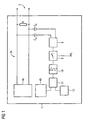
- the device 1 is referred to below as an analog module.
- the analog module receives measured values via the interface 3, which is connected to a two-wire line, not shown.
- This two-wire cable is designed as a 4 ... 20 mA circuit.
- a measuring transducer is connected to this 4 ... 20 mA circuit.
- the measuring transducer in the form of a temperature resistor supplies measured values which are detected by the analog module and forwarded to an automation system assigned to the analog module.
- the measured values corresponding to the current values are measurable as a voltage drop across a resistor R and are conducted via a first signal path 2a to a first evaluation unit 4a.
- the evaluation unit 4a is designed as a digital / analog converter.
- a second evaluation unit 4b is within the Analog module arranged.
- the second evaluation unit 4b is designed to evaluate signals which are in the form of a HART protocol. These HART signals correspond to signals that are modulated onto the 4 ... 20 mA DC circuit of the transmitter.
- Status information that the transducer transmits to the analog module for evaluation in an automation system with subsequent display in an operating and monitoring system are routed via the interface 3 via two coupling capacitors C K to a transformer 8.
- the status signals arrive via a switching means 9 by means of an amplifier 10 via a modem 11 to the second evaluation unit 4b.
- the modem 11 is configured as a HART modem.
- diagnostic information of the measured value converters can be forwarded as modulated HART signals to the user program of the programmable controller via the same interface 3. Since the modulated HART signal corresponds to a zero mean sinusoidal signal, it does not affect the temperature signals.
- signals can be sent via the interface 3 into the process or to the transducers via the amplifier 10 and via the switching means 9 by means of the transformer 8 via the coupling capacitors CK.
- These signals are so-called unsafe signals because the parameters of a transducer can be changed with these signals.
- the measuring range of a transducer can be changed, which means that this transducer now provides measured values to the analog module in comparison to previously scaled measured values. If the user program of the programmable controller was not previously adjusted to these newly scaled measured values, the programmable controller may react incorrectly to certain measured values and the safety of the plant to be automated is at risk.
- modulated non-safe signals have not previously been used as additional signals in fail-safe programmable controllers.
- an observable shut-off mechanism is present in the switching means 9, which monitors and checks the signal path of the non-secure parameterization signals.
- a readback signal is generated via a further signal line, which triggers a safety-ensuring action in the associated automation device.
- the analog module For example, it is possible to receive measured value signals via a single two-wire data line, which is connected to the interface 3, and to transmit unsafe signals, for example parameterizing signals, for the measuring transducer via one and the same two-wire data line.
- FIG. 2 is that in the FIG. 1 already described switching means 9 shown in more detail.
- the strands 2b and 2c form a second and a third signal path, which are connected via a HART modem N1 with an automation device, not shown.
- the second signal path 2b is connected to the HART modem N1 by means of an amplifier N3.
- a fifth switch S12 designed as an opener connects the second signal path 2b and thus the HART modem to a transformer 8, which in turn is coupled to the interface 3 or the two-wire data line already described in FIG.
- the second signal path 2b is a reception path for signals directed to the HART modem N1.
- the third signal path 2c is on Transmission path for signals directed from the HART modem N1 via an amplifier N2 to the process. Parameterizing signals emanating from the HART modem N1 thus reach the transformer 8 in the two-wire data line via the third switch S3, which is designed as a normally closed contact, and via the fourth switch S11, which is designed as a make contact.
- the fourth switch S11 in the third signal path 2c and the fifth switch S12 in the second signal path 2b work together like a changeover switch. When the fifth switch S12 for receiving data on the second signal path 2b is closed, the fourth switch S11 is open for sending data in the signal path 2b, and vice versa.
- the fourth switch S11 and the fifth switch S12 are combined to form a transceiver 14.
- the third switch S3 arranged within the third signal path 2c is designed as an opener and is in operative connection with a first switch S1. If the third switch S3 is opened to check the fourth switch S11 in the third signal path 2c, then the first switch S1 is closed at the same time and thus applies a positive supply voltage via a 10 kOhm resistor R2 to the measuring point MS or to a signal line for a readback signal RL.
- the junction of the second signal path 2b and the third signal path 2c behind the fourth switch S11 and the fifth switch S12 via a second switch S2 is connected to a ground potential.
- the transceiver 14, which consists of the fourth switch S11 and the fifth switch S12, is used to test the fail-safe shutdown of the third signal path 2c by means of the third switch S3.
Landscapes
- Physics & Mathematics (AREA)
- General Physics & Mathematics (AREA)
- Engineering & Computer Science (AREA)
- Automation & Control Theory (AREA)
- Arrangements For Transmission Of Measured Signals (AREA)
Claims (9)
- Dispositif ( 1 ) de détection d'un premier et deuxième types de signaux par l'intermédiaire d'une interface ( 3 ) conjointe, l'interface ( 3 ) étant une interface de courant à deux fils pour un transducteur de valeur de mesure, l'interface ( 3 ) étant reliée par une première voie ( 2a ) de signalisation à une première unité ( 4a ) d'exploitation pour détecter le premier type de signaux, et l'interface ( 3 ) étant reliée par une deuxième voie ( 2b ) de signalisation à une deuxième unité ( 4b ) d'exploitation pour la détection du deuxième type de signaux, un moyen ( 9 ) de commutation étant prévu pour relier une troisième voie ( 2c ) de signalisation à l'interface (3), le moyen ( 9 ) de commutation reliant la troisième voie (2c) de signalisation à l'interface ( 3 ), une source (12) de signal raccordée à la troisième voie ( 2c ) de signalisation étant présente et envoyant un troisième type de signaux à l'interface ( 3 ), caractérisé en ce que le moyen ( 9 ) de commutation est tel qu'une connexion et une redéconnexion contrôlée de la troisième voie ( 2c ) de signalisation est possible et qu'ainsi le troisième type de signaux peut être transmis d'une manière sûre et contrôlée.
- Dispositif ( 1 ) suivant la revendication 1, dans lequel le moyen ( 9 ) de commutation comporte un cinquième interrupteur ( S12 ) dans la deuxième voie ( 2b ) de signalisation et un quatrième interrupteur ( S11 ) dans la troisième voie ( 2c ) de signalisation, lesquels sont montés de manière à pouvoir relier au choix la deuxième ou la troisième voie ( 2b, 2c ) de signalisation à l'interface ( 3 ), dans lequel, pour le contrôle de l'état de commutation du quatrième interrupteur ( S11 ), il y a un deuxième interrupteur ( S2 ), un point ( MS ) de mesure et un premier interrupteur ( S1 ), le troisième interrupteur ( S3 ) étant monté dans un circuit série avec le quatrième interrupteur ( S11 ), la deuxième borne du troisième interrupteur ( S3 ) étant reliée à la première borne du quatrième interrupteur et le premier interrupteur ( S1 ) étant raccordé par sa première borne entre le troisième interrupteur ( S3 ) et le quatrième interrupteur ( S11 ), ce point de raccordement formant le point ( MS ) de mesure, et dans lequel une tension de système est appliquée à la deuxième borne du premier interrupteur ( S1 ), le deuxième interrupteur ( S2 ) étant relié, en outre, par sa deuxième borne à la deuxième borne du quatrième interrupteur ( S11 ) et la première borne du deuxième interrupteur ( S2 ) est reliée à un potentiel de masse, le premier interrupteur ( S1 ), le deuxième interrupteur ( S2 ) et le troisième interrupteur ( S3 ) étant, en outre, dans une relation de travail, dans lequel, en actionnant les interrupteurs ( S1, S2, S3 ) en la relation de travail, un signal d'état peut être produit au point ( MS ) de mesure et donner une prédiction sur l'état de commutation du quatrième interrupteur ( S11 ).
- Dispositif ( 1 ) suivant la revendication 2, dans lequel il est monté un modem ( 11 ) HART et un amplificateur ( 10 ) entre la source ( 12 ) de signal et le circuit série allant du troisième interrupteur ( S3 ) au quatrième interrupteur ( S11 ).
- Dispositif (1) suivant la revendication 1 ou 2, dans lequel le transducteur de valeur de mesure peut être paramétré par l'intermédiaire de l'interface ( 3 ).
- Procédé de détection et d'émission de signaux pour des composants d'automatisation sécurisés vis-à-vis de l'erreur, dans lequel on envoie un premier type de signaux à une première unité (4a) d'exploitation par l'intermédiaire de l'interface ( 3 ) et la liaison entre la première unité ( 4a ) et l'interface ( 3 ) forme une première voie ( 2a ) de signalisation et dans lequel une autre liaison de l'interface ( 3 ) avec une deuxième unité ( 4b ) d'exploitation forme une deuxième voie ( 2b ) de signalisation, par lequel un deuxième type de signaux est envoyé à la deuxième unité ( 2b ) d'exploitation, l'interface ( 3 ) fonctionnant en interface de courant à deux fils pour un transducteur de valeur de mesure, caractérisé en ce que, à l'aide d'un moyen ( 9 ) de commutation pour la connexion et la déconnexion d'une troisième voie ( 2c ) de signalisation en liaison avec l'interface ( 3 ), on envoie par l'interface ( 3 ), d'une manière contrôlée par une séparation pouvant être testée de la troisième voie ( 2c ) de signalisation, un troisième type de signaux influençant la sécurité de l'installation d'automatisation, la séparation de la troisième voie ( 2c ) de signalisation étant contrôlée.
- Procédé suivant la revendication 5, dans lequel on actionne à l'intérieur du moyen ( 9 ) de commutation un troisième interrupteur ( S3 ), qui sépare la troisième voie ( 2c ) de signalisation, dans lequel on actionne pour l'envoi du troisième type de signaux un quatrième interrupteur ( S11 ) du moyen ( 9 ) de commutation, interrupteur qui déconnecte la troisième voie ( 2c ) de signalisation pour émettre le troisième type de signaux vers l'interface ( 3 ), dans lequel, par l'intermédiaire d'un premier commutateur ( S1 ) comportant le moyen ( 9 ) de commutation, on produit un signal ( RL ) de lecture en retour, dans lequel le troisième interrupteur ( S3 ) et le premier interrupteur ( S1 ) sont actionnés ensemble suivant une interaction, le circuit série composé du premier interrupteur ( S1 ) et du quatrième interrupteur ( S11 ) étant relié par l'intermédiaire d'un deuxième interrupteur ( S2 ) à un potentiel différent du signal ( RL ) de lecture en retour et la séparation de la troisième voie ( 2c ) de signalisation étant ainsi testée.
- Procédé suivant l'une des revendications 5 à 6, dans lequel le moyen ( 9 ) de commutation comporte un cinquième interrupteur ( S12 ), qui, pendant que le quatrième interrupteur ( S11 ) est fermé, est ouvert en relation d'alternance avec le quatrième interrupteur ( S11 ) et découple la deuxième voie ( 2c ) de signalisation de l'interface ( 3 ).
- Procédé suivant la revendication 7, dans lequel on contrôle cycliquement le fonctionnement du quatrième interrupteur ( S11 ) en ce qui concerne la sécurité de l'ouverture.
- Procédé suivant la revendication 7 ou 8, dans lequel, si le quatrième interrupteur ( S11 ) fonctionne d'une manière défectueuse, on déclenche une action assurant la sécurité.
Priority Applications (2)
| Application Number | Priority Date | Filing Date | Title |
|---|---|---|---|
| EP08002772A EP2090946B1 (fr) | 2008-02-14 | 2008-02-14 | Procédé et dispositif d'enregistrement et d'émission de signaux dans des composants d'automatisation sécurisés |
| DE200850003088 DE502008003088D1 (de) | 2008-02-14 | 2008-02-14 | Verfahren und Vorrichtung zum Erfassen und Aussenden von Signalen bei fehlersicheren Automatisierungskomponenten |
Applications Claiming Priority (1)
| Application Number | Priority Date | Filing Date | Title |
|---|---|---|---|
| EP08002772A EP2090946B1 (fr) | 2008-02-14 | 2008-02-14 | Procédé et dispositif d'enregistrement et d'émission de signaux dans des composants d'automatisation sécurisés |
Publications (2)
| Publication Number | Publication Date |
|---|---|
| EP2090946A1 EP2090946A1 (fr) | 2009-08-19 |
| EP2090946B1 true EP2090946B1 (fr) | 2011-04-06 |
Family
ID=39591395
Family Applications (1)
| Application Number | Title | Priority Date | Filing Date |
|---|---|---|---|
| EP08002772A Active EP2090946B1 (fr) | 2008-02-14 | 2008-02-14 | Procédé et dispositif d'enregistrement et d'émission de signaux dans des composants d'automatisation sécurisés |
Country Status (2)
| Country | Link |
|---|---|
| EP (1) | EP2090946B1 (fr) |
| DE (1) | DE502008003088D1 (fr) |
Families Citing this family (1)
| Publication number | Priority date | Publication date | Assignee | Title |
|---|---|---|---|---|
| US10933997B2 (en) * | 2015-10-02 | 2021-03-02 | Insitu, Inc. | Aerial launch and/or recovery for unmanned aircraft, and associated systems and methods |
Citations (1)
| Publication number | Priority date | Publication date | Assignee | Title |
|---|---|---|---|---|
| WO2008015096A1 (fr) * | 2006-08-04 | 2008-02-07 | Endress+Hauser Wetzer Gmbh+Co. Kg | Unité de séparation pour une connexion de communication traditionnelle à deux conducteurs qui comprend un capteur, un transformateur de mesure et une unité de commande |
Family Cites Families (5)
| Publication number | Priority date | Publication date | Assignee | Title |
|---|---|---|---|---|
| US4155116A (en) | 1978-01-04 | 1979-05-15 | The Bendix Corporation | Digital control system including built in test equipment |
| DE19909403B4 (de) * | 1999-03-05 | 2004-08-26 | Conti Temic Microelectronic Gmbh | Verfahren zur Steuerung eines Insassenschutzsystems |
| DE10127056A1 (de) * | 2001-06-02 | 2002-12-05 | Bosch Gmbh Robert | Vorrichtung zur sicheren Signalerzeugung |
| DE10127561B4 (de) | 2001-06-06 | 2006-11-02 | Bundesrepublik Deutschland, vertr. d. d. Bundesministerium für Wirtschaft und Technologie, dieses vertr. d. d. Präsidenten der Physikalisch-Technischen Bundesanstalt | Eigensicheres Feldbussystem |
| DE502004011795D1 (de) * | 2004-05-05 | 2010-12-02 | Siemens Ag | Schaltungsanordnung sowie Verfahren zum Testen von Relaisschaltkontakten einer digitalen Ausgangsschaltung |
-
2008
- 2008-02-14 EP EP08002772A patent/EP2090946B1/fr active Active
- 2008-02-14 DE DE200850003088 patent/DE502008003088D1/de active Active
Patent Citations (1)
| Publication number | Priority date | Publication date | Assignee | Title |
|---|---|---|---|---|
| WO2008015096A1 (fr) * | 2006-08-04 | 2008-02-07 | Endress+Hauser Wetzer Gmbh+Co. Kg | Unité de séparation pour une connexion de communication traditionnelle à deux conducteurs qui comprend un capteur, un transformateur de mesure et une unité de commande |
Also Published As
| Publication number | Publication date |
|---|---|
| DE502008003088D1 (de) | 2011-05-19 |
| EP2090946A1 (fr) | 2009-08-19 |
Similar Documents
| Publication | Publication Date | Title |
|---|---|---|
| DE102004015617B4 (de) | Online-Geräteprüfblock, der in ein Prozeßsteuerungs-/Sicherheitssystem integriert ist | |
| EP3170287B1 (fr) | Système de commande et de transmission de données, module de passerelle, module e/a et procédé de commande de processus | |
| EP2171549B1 (fr) | Dispositif de sécurité pour la commande par plusieurs canaux d'un dispositif de la technique de sécurité | |
| EP1296207B1 (fr) | Appareil HMI et procédé de commande d'une installation technique, système d'automatisation avec cet appareil HMI et produit de programme informatique avec un programme pour la mise en oeuvre de ce procédé dans un appareil HMI ou dans un système d'automatisation | |
| DE102013103380A1 (de) | Steuer- und Datenübertragungsanlage, Prozesseinrichtung und Verfahren zur redundanten Prozesssteuerung mit dezentraler Redundanz | |
| EP2161638A1 (fr) | Système d'automatisation, appareil destiné à l'utilisation dans un système d'automatisation et procédé de fonctionnement d'un système d'automatisation | |
| EP3414632B1 (fr) | Procédé et dispositif pour contrôler un traitement et une transmission de données dans une chaîne de sécurité d'un système de sécurité | |
| DE112013002661T5 (de) | Segment mit einer Fehlerschutzeinrichtung für ein zweidrahtiges, kombiniert verbundenes Energie- und Datennetzsystem | |
| EP3283928B1 (fr) | Procédé de branchement ou de débranchement automatique d'une résistance de communication d'un dispositif hart | |
| WO2012065808A1 (fr) | Procédé d'établissement d'un diagnostic d'un appareil de terrain | |
| EP2375636A1 (fr) | Dispositif et procédé de configuration d'un système de bus | |
| EP3470939B1 (fr) | Procédé et système de surveillance de l'intégrité de sécurité d'une fonction de sécurité fournie par un système de sécurité | |
| EP1251416B1 (fr) | Dispositif de diagnostic pour un dispositif de terrain avec transmission des informations de manière indépendante de la commande | |
| WO2007137988A2 (fr) | Transducteur de mesure | |
| WO2012065807A1 (fr) | Procédé de préparation d'un message de diagnostic général pour tous les types d'appareil de terrain | |
| EP2090946B1 (fr) | Procédé et dispositif d'enregistrement et d'émission de signaux dans des composants d'automatisation sécurisés | |
| EP3470937A1 (fr) | Procédé et dispositifs de surveillance du temps réactionnel d'une fonction de sécurité fournie par un système de sécurité | |
| EP2767877B1 (fr) | Système de commande et de transmission de données pour la transmission de données liées à la sécurité via un bus de terrain | |
| EP1788484A2 (fr) | Procédé et dispositif de diagnostic d'un système de bus avec un nombre d'utilisateurs | |
| EP3692686A1 (fr) | Procédé de fonctionnement d'une installation de technique de l'automatisation | |
| WO2010026011A1 (fr) | Procédé de fonctionnement d'un appareil pour l'automatisation de processus | |
| DE102012010144B3 (de) | Analogsignal-Ausgangsschaltung mit einer Anzahl von Analogsignal-Ausgabekanälen | |
| EP1748334A1 (fr) | Procédé et dispositif pour surveiller un milieu de transmission | |
| EP2733718A2 (fr) | Procédé et dispositif d'évaluation de signaux provenant d'un élément de sortie OSSD | |
| EP2950174A1 (fr) | Méthode et appareil pour surveiller en toute sécurité l'état de deux dispositifs |
Legal Events
| Date | Code | Title | Description |
|---|---|---|---|
| PUAI | Public reference made under article 153(3) epc to a published international application that has entered the european phase |
Free format text: ORIGINAL CODE: 0009012 |
|
| AK | Designated contracting states |
Kind code of ref document: A1 Designated state(s): AT BE BG CH CY CZ DE DK EE ES FI FR GB GR HR HU IE IS IT LI LT LU LV MC MT NL NO PL PT RO SE SI SK TR |
|
| AX | Request for extension of the european patent |
Extension state: AL BA MK RS |
|
| 17P | Request for examination filed |
Effective date: 20100208 |
|
| 17Q | First examination report despatched |
Effective date: 20100303 |
|
| AKX | Designation fees paid |
Designated state(s): DE FR GB IT |
|
| GRAP | Despatch of communication of intention to grant a patent |
Free format text: ORIGINAL CODE: EPIDOSNIGR1 |
|
| RIC1 | Information provided on ipc code assigned before grant |
Ipc: G05B 19/042 20060101AFI20101013BHEP Ipc: G08C 19/02 20060101ALI20101013BHEP |
|
| RTI1 | Title (correction) |
Free format text: METHOD AND DEVICE FOR RECEIVING AND TRANSMITTING SIGNALS FOR SAFETY-ORIENTED AUTOMATION COMPONENTS |
|
| GRAS | Grant fee paid |
Free format text: ORIGINAL CODE: EPIDOSNIGR3 |
|
| GRAA | (expected) grant |
Free format text: ORIGINAL CODE: 0009210 |
|
| AK | Designated contracting states |
Kind code of ref document: B1 Designated state(s): DE FR GB IT |
|
| REG | Reference to a national code |
Ref country code: GB Ref legal event code: FG4D Free format text: NOT ENGLISH |
|
| REF | Corresponds to: |
Ref document number: 502008003088 Country of ref document: DE Date of ref document: 20110519 Kind code of ref document: P |
|
| REG | Reference to a national code |
Ref country code: DE Ref legal event code: R096 Ref document number: 502008003088 Country of ref document: DE Effective date: 20110519 |
|
| PLBE | No opposition filed within time limit |
Free format text: ORIGINAL CODE: 0009261 |
|
| STAA | Information on the status of an ep patent application or granted ep patent |
Free format text: STATUS: NO OPPOSITION FILED WITHIN TIME LIMIT |
|
| 26N | No opposition filed |
Effective date: 20120110 |
|
| REG | Reference to a national code |
Ref country code: DE Ref legal event code: R097 Ref document number: 502008003088 Country of ref document: DE Effective date: 20120110 |
|
| REG | Reference to a national code |
Ref country code: FR Ref legal event code: PLFP Year of fee payment: 9 |
|
| REG | Reference to a national code |
Ref country code: FR Ref legal event code: PLFP Year of fee payment: 10 |
|
| REG | Reference to a national code |
Ref country code: FR Ref legal event code: PLFP Year of fee payment: 11 |
|
| PGFP | Annual fee paid to national office [announced via postgrant information from national office to epo] |
Ref country code: IT Payment date: 20200224 Year of fee payment: 13 |
|
| PG25 | Lapsed in a contracting state [announced via postgrant information from national office to epo] |
Ref country code: IT Free format text: LAPSE BECAUSE OF NON-PAYMENT OF DUE FEES Effective date: 20210214 |
|
| PGFP | Annual fee paid to national office [announced via postgrant information from national office to epo] |
Ref country code: DE Payment date: 20250417 Year of fee payment: 18 |
|
| PGFP | Annual fee paid to national office [announced via postgrant information from national office to epo] |
Ref country code: GB Payment date: 20260310 Year of fee payment: 19 |
|
| PGFP | Annual fee paid to national office [announced via postgrant information from national office to epo] |
Ref country code: FR Payment date: 20260213 Year of fee payment: 19 |