EP2091132B1 - Moteur à commutation électronique - Google Patents
Moteur à commutation électronique Download PDFInfo
- Publication number
- EP2091132B1 EP2091132B1 EP09001372.3A EP09001372A EP2091132B1 EP 2091132 B1 EP2091132 B1 EP 2091132B1 EP 09001372 A EP09001372 A EP 09001372A EP 2091132 B1 EP2091132 B1 EP 2091132B1
- Authority
- EP
- European Patent Office
- Prior art keywords
- conductor
- section
- distance
- stator
- predetermined angle
- Prior art date
- Legal status (The legal status is an assumption and is not a legal conclusion. Google has not performed a legal analysis and makes no representation as to the accuracy of the status listed.)
- Active
Links
Images



Classifications
-
- H—ELECTRICITY
- H02—GENERATION; CONVERSION OR DISTRIBUTION OF ELECTRIC POWER
- H02K—DYNAMO-ELECTRIC MACHINES
- H02K3/00—Details of windings
- H02K3/04—Windings characterised by the conductor shape, form or construction, e.g. with bar conductors
- H02K3/28—Layout of windings or of connections between windings
-
- H—ELECTRICITY
- H02—GENERATION; CONVERSION OR DISTRIBUTION OF ELECTRIC POWER
- H02K—DYNAMO-ELECTRIC MACHINES
- H02K3/00—Details of windings
- H02K3/46—Fastening of windings on the stator or rotor structure
- H02K3/52—Fastening salient pole windings or connections thereto
- H02K3/521—Fastening salient pole windings or connections thereto applicable to stators only
- H02K3/522—Fastening salient pole windings or connections thereto applicable to stators only for generally annular cores with salient poles
-
- H—ELECTRICITY
- H02—GENERATION; CONVERSION OR DISTRIBUTION OF ELECTRIC POWER
- H02K—DYNAMO-ELECTRIC MACHINES
- H02K2203/00—Specific aspects not provided for in the other groups of this subclass relating to the windings
- H02K2203/09—Machines characterised by wiring elements other than wires, e.g. bus rings, for connecting the winding terminations
-
- H—ELECTRICITY
- H02—GENERATION; CONVERSION OR DISTRIBUTION OF ELECTRIC POWER
- H02K—DYNAMO-ELECTRIC MACHINES
- H02K2203/00—Specific aspects not provided for in the other groups of this subclass relating to the windings
- H02K2203/12—Machines characterised by the bobbins for supporting the windings
Definitions
- the invention relates to an electronically commutated motor.
- Some applications require electronically commutated motors that start within a very short time and are therefore designed to provide high torque and low internal resistance.
- the EP 1 677 404 A2 shows a motor with a stator, a rotatably mounted rotor and an output stage.
- the stator has 12 distinct stator poles with associated stator coils.
- the stator coils are interconnected via connecting rings which are formed as stationary busbars and arranged in a holder.
- the EP 1 526 628 A1 , the US 2003/0094879 A1 and the DE 103 18 816 A1 show stators with Verschalt tone, which are each arranged concentrically.
- the WO 2006 / 120054A1 shows an electric motor with a stator unit, the Verschaltium having a plurality of different shapes aufwesit.
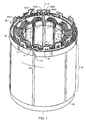
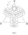
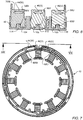
- Fig. 1 shows the stator 30 of a three-phase motor 32 ( Fig. 4 ), which has here as an example a permanent magnetic inner rotor 34, which in Fig. 4 is indicated only schematically and, depending on the design of the motor 32 may naturally have different types and poles, as is known to those skilled in electrical machinery. Shown is an eight-pole rotor.
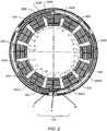
- the laminated core 36 has twelve grooves 1 to 12, which are insulated in the usual way, for example by means of a (not shown) plastic coating. These define twelve pronounced poles. Each pole is wound with a coil, and these coils are designated 1 'to 12'.
- the stator 30 has in the usual way a laminated core (lamination stack) 36, at its in Fig. 1 lower end of an insulating ring 38 is mounted, which is part of the bobbin forms for the stator winding.
- This ring 38 is sometimes referred to as "end plate” and carries in this embodiment no electrical connection elements, but serves only as part of the bobbin and as an insulator for the winding, but may have the same shape as in Fig. 6 , below, but without the three busbars in the upper part of Fig. 6 are shown and the lower ring 38 are not needed.
- an insulating ring 42 which may also be referred to as an annular disc, and which also functions to serve as part of and as an insulator for the coil.
- This upper ring 42 carries in this embodiment, three upstanding busbars 44, 46, 48, which may be identical, but against each other in the manner by 120 ° mech. are angularly offset, like that from the Fig. 2 . 6 and 7 evident.
- Fig. 5 shows the bus bar 44, which is usually - for practical reasons - made identical to the busbars 46 and 48, which is why the individual bus bars contain redundant parts, which could of course be omitted, but in most cases would increase the cost.
- the busbars 44, 46, 48 are parts that are simple to the eye, but in terms of their functions, they are based on a long and difficult development and on many innovative steps, since they have to perform very different functions optimally.
- Each bus bar 44, 46, 48 in the embodiment has approximately the shape of a ring segment and in this example extends over about 280 to about 300 ° mech., Preferably about 295 ° mech. each ring has a missing piece 50, which enables the three rings 44, 46, 48 to be skilfully nested together, prevented from twisting relative to each other, to easily provisionally secure the winding wire at its ends, and to prevent improper assembly ,
- Fig. 5 shows, has the bus bar 44 at its in Fig. 5 lower portion 56 an elongated recess 58, which serves for connection to a plug 60 which in Fig. 11 is shown and serves to provide the motor 32 with electrical energy.
- This recess 58 is located approximately opposite a notch 60, according to Fig. 8 is used to engage with a projection 110 of the ring 42, whereby the latter is prevented from twisting at this point relative to the respective busbar, ie the groove 60U of the busbar 46 (U) and the projection 114 serve the busbar 46 (U ) in the region of the associated projection 110 to be largely immobilized, as is advantageous for a mechanical production.
- the recess 58 When viewed in the clockwise direction, the recess 58 is followed by a hook 62, which is punched out of the busbar 44 and bent inwards as shown. At this hook 62, a winding wire 63 is initially hung during winding, cf. Fig. 12 , and then welded by resistance welding to the hook 62, which can be done with an automatic device.
- FIG. 13 shows a resistance welding, in which the line 63 by means of welding tongs, which is closed in the direction of two arrows 69, 71, welded to the hook 62.
- the two jaws 65, 67 of the welding gun are guided from above over the hook 62 and then brought in the direction of arrows 69, 71 to this.
- the hook 62 is bent together by means of the jaws 65, 67 above the conduit 63 and at the same time heated by a current flowing through the jaws 65, 67. By this current, the wire 63 is heated, whereby its insulation burns off.
- the line 63 is welded to the hook 62, and there is a mechanically stable and electrically good conductive connection.
- FIGS. 12 and 13 are schematic representations that indicate the ring 42 and the other parts only very roughly, to illustrate the working principle of welding in a simple and understandable way.
- the hook 62 follows a section 64 with a length of about 60 ° mech., Where the bus bar 44 has a rectangular cross-section without special features. This is followed by a section 66 with a hook 68, and then an elongated recess 70, wherein in section 66 a notch 72 is provided.
- the section 66 is followed by a bending point 74, at which the radius r1 of the section 64 decreases to a slightly smaller radius r2 of a section 78, which - like the section 64 - an angular extent of about 60 ° mech. Has.
- the portion 78 extends to a bend 80, where the radius r2 of the portion 78 to a slightly smaller Radius r3 reduced.
- the bending points 74, 80 are guided in corresponding complementary mold cavities B of the ring 33, which in the lower part of Fig. 6 are shown. They prevent the rings 44, 46, 48 from being inserted in the ring 42 differently than in predetermined positions.
- Fig. 5 follows, in a clockwise direction, a hook 82 on the bending point 80, and then, with a distance of about 40 ° mech. from the hook 82, one of the busbar 44 upstanding portion 84 with an elongated recess 86, which also here a notch 88 opposite.
- the hooks 62, 68, 82, 92 and 94 protrude into the interior of the respective busbar 44, 46 or 48.
- the winding wire 63 is hooked in the automated winding and then welded to the respective busbar, wherein the heat Welding occurs, the insulation of the wire 63 is burned off, so that a good electrical connection is formed.
- busbars 44 (W), 46 (U) and 48 (V) may be identical, their elements are denoted by the same reference numerals as in Fig. 5 , but indicated with U, V or W, eg 68U, 68V or 68W, so as not to complicate the presentation.
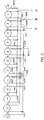
- the entire winding for all phases is wound from a single, continuous piece of wire 63, whose one end 63A is electrically and mechanically connected to the hook 92W of the part 90W, then all twelve coils 8 ', 9', 10 ', 11 ', 12', 1 ', 2', 3 ', 4', 5 ', 6' and 7 'passes through to its other end 63B.
- the end 63B is electrically and mechanically connected to the hook 94W of the part 90W so that the winding wire 63 is preferably self-contained.
- the wire 63 continues to the coil 12 ', and from this to the hook 62U, and on to the coil 1'. From this, the wire 63 continues to the hook 68W, and from there via the spool 2 'to the hook 82V and further, via the spool 3', to the hook 94U. (Hook 92U is not used on this busbar).
- the winding passes via the coil 4 'to the hook 62W, and from there via the coil 5' to the hook 68V, and from there via the coil 6 'to the hook 82W, and then via the coil 7' to the wire end 63B ( Fig. 3 ) and hook 94W.
- stator winding assembly 30 Since the currents in the stator winding assembly 30 can be significant, it is important to provide low resistance connections throughout the motor (or generator).
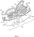
- Fig. 9 shows a perspective view of a portion of the upper insulating ring 42.
- This has a mold cavity 100 for receiving the bus bar 46 (U), a mold cavity 102 for receiving the bus bar 48 (V), and a mold cavity 104 for receiving the bus bar 44 (W) ,
- the busbars are pressed into these cavities and held there. Because of the heating that takes place during welding, the part 42 is preferably crosslinked by radiation so that it can withstand these elevated temperatures.
- the insulating ring 42 has a mark 110, here for example in the form of a longitudinal groove, and the three busbars 44, 46, 48 are locked in this area 108 by special projections in the circumferential direction: A projection 112 ( Fig. 8 ) at the bottom of the mold cavity 102, the bus bar 48 (V) locks in the circumferential direction in the mold cavity 102 by positively engaging in the groove 88 V of the bus bar 48.
- the busbar 48 is fixed exactly in the angular range 108 in the circumferential direction, which proves to be very advantageous for further machine processing.
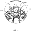
- the elongated openings 70W, 86V and 58U have the Fig. 9 a precisely defined position relative to one another and to the longitudinal groove 110 (FIG. Fig. 9 ), so that in these elongated openings according to Fig. 10 three flat conductors 120, 122, 124 can be inserted from a side power connector 60, like the Fig. 10 and these flat conductors 120, 122, 124 can then be electrically and mechanically connected to the bus bars 44, 46, 48, as by laser welding, as in FIG Fig. 11 shown.
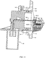
- the flat conductors 120, 122, 124 are secured in the power connector 60 by injection molding, cf. Fig. 11 , and they allow a low-resistance connection from the plug 60 to the stator 30, and this connection can be made largely or completely automated.
- the power plug 60 is inserted with a cylindrical part 130 in a cylindrical recess 132 of a motor housing 134.
- This housing 134 is in Fig. 11 only partially shown.
- An O-ring 136 is inserted into an annular groove 138 of the cylindrical part 130 and serves to seal between this and the motor housing 134.
- the motor connector 60 is fastened by two screws to the motor housing 134, of which the screw 142 in Fig. 11 is visible.
- the three busbars 44, 46, 48 are first pressed into the mold cavities 100, 102, 104 in order to securely hold them there and to achieve a very exact positioning of the busbars in the angular range 108. Then, the stator 30 is wound, usually with a winding machine, and the winding wire 63 is welded to the various hooks in which it is mounted, as in the FIGS. 12 and 13 is shown by way of example.
- the power plug 60 is mounted by laterally inserting and welding the flat traces 120, 122, 124 into the elongated openings 70U, 86V and 58W.
- the end shields (not shown) are assembled together with the shaft and rotor 34. These parts are, since they have no direct relationship to the present invention, indicated only schematically.
Landscapes
- Engineering & Computer Science (AREA)
- Power Engineering (AREA)
- Insulation, Fastening Of Motor, Generator Windings (AREA)
Claims (6)
- Moteur à commutation électronique (32) avec un rotor (34), qui est rotatif autour d'un axe imaginaire (D),
avec un ensemble stator (30), dans lequel un nombre divisible entier par trois ou par un multiple entier de celui-ci de pôles de stator marqués est prévu, auxquels des bobines (1' à 12') sont associées, auxquelles des rails conducteurs (44, 46, 48) agencés debout par rapport à leur raccord électrique sont associés, qui sont agencés dans un élément isolant (42),
caractérisé en ce que
les rails électriques (44, 46, 48) présentent respectivement une section centrale (78), qui s'étend à une distance moyenne (r2) de l'axe imaginaire (D) du rotor (34),
et qui présentent une première section d'extrémité (90), qui s'étend à une première distance (r3) de l'axe imaginaire (D), laquelle première distance (r3) est inférieure à la distance moyenne (r2), laquelle première section (90) passe à la section centrale (78) par le biais d'un premier point de renvoi (80),
et qui présentent une deuxième section d'extrémité (64), qui s'étend à une deuxième distance (r1) de l'axe (D), laquelle deuxième distance (r1) est supérieure à la distance moyenne (r2) et passe à la section centrale (78) par le biais d'un deuxième point de renvoi (74),
lesquels rails électriques (44, 46, 48) sont isolés l'un de l'autre et imbriqués l'un dans l'autre, dans lequel la deuxième section d'extrémité (64) d'un premier rail électrique (46) s'étend dans une plage angulaire prédéfinie (108) de l'ensemble stator (30) jusqu'à proximité d'un deuxième point de renvoi (74) s'y trouvant du deuxième rail électrique (44) directement adjacent à cette deuxième section d'extrémité (64) à ce point,
et la possibilité d'un déplacement desdits rails électriques (44, 46, 48) dans la direction circonférentielle dans cette plage angulaire prédéfinie (108) de l'ensemble stator (30) est limitée mécaniquement par des saillies (44, 46, 48) de l'élément isolant (42), qui entrent en prise par correspondance de forme dans des rainures (72W, 60U, 88V) desdits rails électriques (44, 46, 48). - Moteur selon la revendication 1, dans lequel dans la plage angulaire prédéfinie (108) chacun des rails électriques (44, 46, 48) est pourvu d'une possibilité de raccordement (58U, 86V, 70W) pour un conducteur de raccordement (120, 122, 124) associé dans la direction s'éloignant du moteur (32).
- Moteur selon la revendication 2, dans lequel le conducteur de raccordement (120, 122, 124) est réalisé en tant que conducteur plat,
et dans le rail électrique (44, 46, 48) qui lui est associé, un évidement complémentaire à celui-ci est prévu pour la réception de ce conducteur plat (120, 122, 124). - Moteur selon la revendication 3, dans lequel une liaison soudée est prévue entre un rail électrique (44, 46, 48) et le conducteur plat qui lui associé (120, 122, 124).
- Moteur selon l'une quelconque des revendications précédentes, dans lequel des crochets (62, 68, 82, 92, 94) sont prévus au niveau de chacun des rails électriques (44, 46, 48) pour l'accrochage d'éléments (63) de l'enroulement de stator.
- Moteur selon la revendication 5, dans lequel la distance des crochets (62U, 68W), qui servent à accrocher des éléments (63) de l'enroulement de stator pour les pôles de stator (12', 1', 2') de la plage angulaire prédéfinie (108), est supérieure à cette plage angulaire prévue (108).
Applications Claiming Priority (1)
| Application Number | Priority Date | Filing Date | Title |
|---|---|---|---|
| DE102008009845 | 2008-02-12 |
Publications (3)
| Publication Number | Publication Date |
|---|---|
| EP2091132A2 EP2091132A2 (fr) | 2009-08-19 |
| EP2091132A3 EP2091132A3 (fr) | 2017-03-15 |
| EP2091132B1 true EP2091132B1 (fr) | 2019-04-03 |
Family
ID=40627467
Family Applications (1)
| Application Number | Title | Priority Date | Filing Date |
|---|---|---|---|
| EP09001372.3A Active EP2091132B1 (fr) | 2008-02-12 | 2009-02-02 | Moteur à commutation électronique |
Country Status (3)
| Country | Link |
|---|---|
| US (1) | US8339001B2 (fr) |
| EP (1) | EP2091132B1 (fr) |
| DE (2) | DE202009000415U1 (fr) |
Families Citing this family (32)
| Publication number | Priority date | Publication date | Assignee | Title |
|---|---|---|---|---|
| EP2256906A4 (fr) * | 2007-11-09 | 2014-10-15 | Mitsubishi Electric Corp | Stator pour machine électrique tournante et son procédé de fabrication |
| GB2466090A (en) * | 2008-12-12 | 2010-06-16 | Zhongshan Broad Ocean Motor Co | Interconnecting concentrated stator windings |
| IT1397784B1 (it) * | 2010-01-15 | 2013-01-24 | Gate Srl | Collettore per lo statore di un motore brushless in corrente continua a magneti permanenti |
| IT1401830B1 (it) * | 2010-09-29 | 2013-08-28 | Magneti Marelli Spa | Macchina elettrica presentante un avvolgimento statorico con barre rigide e relativo metodo di costruzione |
| DE102012202131A1 (de) * | 2012-02-13 | 2013-08-14 | Brose Fahrzeugteile GmbH & Co. Kommanditgesellschaft, Würzburg | Statoranordnung und elektrische Maschine |
| JP5736339B2 (ja) * | 2012-03-30 | 2015-06-17 | カヤバ工業株式会社 | バスバーユニット |
| JP5789570B2 (ja) * | 2012-07-03 | 2015-10-07 | アイシン・エィ・ダブリュ株式会社 | ステータ |
| US20140015359A1 (en) * | 2012-07-11 | 2014-01-16 | Remy Technologies, Llc | Buss bar assembly having printed buss bar plates |
| FR2996072B1 (fr) * | 2012-09-26 | 2016-07-29 | Sonceboz Automotive Sa | Ensemble de connexion electrique pour moteur sans balai |
| DE102013003024A1 (de) * | 2013-02-22 | 2014-08-28 | Brose Fahrzeugteile GmbH & Co. Kommanditgesellschaft, Würzburg | Elektromotor, insbesondere einer Fahrzeugkomponente |
| KR102051599B1 (ko) * | 2013-09-16 | 2020-01-08 | 엘지이노텍 주식회사 | 버스바, 인슐레이터 및 이를 포함하는 모터 |
| JP6125385B2 (ja) * | 2013-09-17 | 2017-05-10 | 愛三工業株式会社 | ステータ用端子 |
| JP6185826B2 (ja) * | 2013-11-27 | 2017-08-23 | タイコエレクトロニクスジャパン合同会社 | モータ用コネクタ及びモータ用コネクタ組立体 |
| JP6204188B2 (ja) * | 2013-12-27 | 2017-09-27 | トヨタ自動車株式会社 | 回転電機のステータ |
| DE102014201637A1 (de) | 2014-01-30 | 2015-07-30 | Ovalo Gmbh | Stromschiene für einen Stator, Stator, Elektromotor und Verfahren zum Herstellen eines Stators |
| US10622861B2 (en) | 2015-03-31 | 2020-04-14 | Aisin Aw Co., Ltd. | Stator and bus bar connector configuration |
| DE102015209041A1 (de) * | 2015-05-18 | 2016-11-24 | Robert Bosch Gmbh | Stator für eine elektrische Maschine, sowie Verfahren zur Herstellung eines solchen |
| DE102015110624A1 (de) * | 2015-07-01 | 2017-01-05 | Metabowerke Gmbh | Stator für einen Elektromotor |
| EP3425776B1 (fr) | 2016-03-02 | 2021-05-05 | LG Innotek Co., Ltd. | Ensemble de barre omnibus et moteur le comprenant |
| DE102016224425A1 (de) * | 2016-12-08 | 2018-06-14 | Robert Bosch Gmbh | Stator für einen Mehrphasen-Elektromotor, Verfahren zur Herstellung einer Spulenwicklung, und Elektromotor für ein handgehaltenes Werkzeug |
| EP3352341B1 (fr) * | 2017-01-20 | 2025-07-30 | Ovalo GmbH | Stator et procédé de fabrication d'un stator |
| DE102017106399B4 (de) * | 2017-03-24 | 2023-10-05 | Nidec Corporation | Elektromotor |
| JP6272525B1 (ja) * | 2017-04-21 | 2018-01-31 | 三菱電機株式会社 | 回転電機 |
| DE102018102033A1 (de) * | 2018-01-30 | 2019-08-01 | Ebm-Papst St. Georgen Gmbh & Co. Kg | Statorvorrichtung mit Verschalt-Endscheibe für einen Elektromotor und Verwendung der Statorvorrichtung |
| CN108667182B (zh) * | 2018-05-20 | 2019-07-09 | 蔚然(南京)动力科技有限公司 | 三层绕组电动机定子变极变速法 |
| KR102656510B1 (ko) | 2018-12-11 | 2024-04-12 | 엘지이노텍 주식회사 | 모터 |
| JP7270783B2 (ja) * | 2019-08-20 | 2023-05-10 | 安徽威▲靈▼汽▲車▼部件有限公司 | 母線、母線本体、モータ、電動パワーステアリングシステム及び車両 |
| WO2021247954A1 (fr) | 2020-06-05 | 2021-12-09 | Milwaukee Electric Tool Corporation | Moteur sans balais pour outil électrique |
| FR3124656B1 (fr) * | 2021-06-23 | 2023-06-30 | Valeo Equip Electr Moteur | Unité électronique pour convertisseur de tension de machine électrique tournante. |
| DE102021133409A1 (de) | 2021-12-16 | 2023-06-22 | Minebea Mitsumi Inc. | Stator für eine elektrische Maschine |
| CN117856499A (zh) * | 2022-09-30 | 2024-04-09 | 日本电产株式会社 | 马达 |
| JP2025023736A (ja) * | 2023-08-04 | 2025-02-17 | 株式会社ミツバ | モータ |
Family Cites Families (10)
| Publication number | Priority date | Publication date | Assignee | Title |
|---|---|---|---|---|
| US4926075A (en) * | 1987-12-28 | 1990-05-15 | Makita Electric Works, Ltd. | Electric motor brush assembly adaptable to different stators |
| JP3733316B2 (ja) * | 2001-10-26 | 2006-01-11 | 住友電装株式会社 | 車両用薄型ブラシレスモータの集中配電部材 |
| DE10261611A1 (de) | 2002-12-27 | 2004-07-08 | Robert Bosch Gmbh | Verschaltelement für eine Wicklung einer elektrischen Maschine |
| DE10318816B4 (de) * | 2003-04-17 | 2007-06-28 | Minebea Co., Ltd. | Stator mit Verschaltungsstruktur für Statorwicklungen |
| JP4295319B2 (ja) * | 2003-06-20 | 2009-07-15 | シーメンス アクチエンゲゼルシヤフト | 回路支持体を有する回転電機 |
| DE10328720A1 (de) | 2003-06-25 | 2005-01-27 | Robert Bosch Gmbh | Verschaltungselement für eine Wicklung einer elektrischen Maschine |
| DE50313509D1 (de) * | 2003-10-22 | 2011-04-14 | Brose Fahrzeugteile | Verschaltungseinheit für einen Stator eines Elektromotors |
| JP4783012B2 (ja) * | 2004-12-28 | 2011-09-28 | 日立オートモティブシステムズ株式会社 | 電動パワーステアリング用モータ及びその製造方法 |
| ITMI20050519A1 (it) * | 2005-03-30 | 2006-09-30 | Abb Service Srl | Motore elettrico con dispositivo di connessione migliorato |
| ATE555536T1 (de) * | 2006-01-24 | 2012-05-15 | Alstom Technology Ltd | Verbindungsanordnung für die statorwicklung einer turbomaschine mit 2 oder mehr parallelen kreisen |
-
2009
- 2009-01-28 DE DE202009000415U patent/DE202009000415U1/de not_active Expired - Lifetime
- 2009-01-28 DE DE102009004645A patent/DE102009004645A1/de active Pending
- 2009-02-02 EP EP09001372.3A patent/EP2091132B1/fr active Active
- 2009-02-11 US US12/369,095 patent/US8339001B2/en active Active
Non-Patent Citations (1)
| Title |
|---|
| None * |
Also Published As
| Publication number | Publication date |
|---|---|
| DE202009000415U1 (de) | 2009-06-18 |
| US8339001B2 (en) | 2012-12-25 |
| US20090200879A1 (en) | 2009-08-13 |
| EP2091132A3 (fr) | 2017-03-15 |
| EP2091132A2 (fr) | 2009-08-19 |
| DE102009004645A1 (de) | 2009-08-13 |
Similar Documents
| Publication | Publication Date | Title |
|---|---|---|
| EP2091132A2 (fr) | Moteur électronique commuté | |
| EP1526628B1 (fr) | Unité de connexion d'un stator de moteur électrique | |
| EP1810388B1 (fr) | Moteur electrique | |
| EP3298679B1 (fr) | Stator d'une machine electrique et procédé de production d'un tel stator | |
| EP1642376B1 (fr) | Element de connexion pour bobinage d'une machine electrique | |
| EP2082472B1 (fr) | Moteur électrique | |
| EP3963694B1 (fr) | Procédé de fabrication d'un stator | |
| EP3078099B1 (fr) | Stator pour moteur à courant continu à commutation électronique | |
| DE102005001705A1 (de) | Verfahren zur Herstellung von Ankern, Verfahren zur Herstellung von Elektromotoren sowie Anker | |
| DE102016224526A1 (de) | Stator einer elektrischen Maschine, elektrische Maschine sowie Verlege- und Kontakteinrichtung für eine elektrische Maschine | |
| DE102009016990A1 (de) | Stator, Motor und Verfahren zur Herstellung eines Stators | |
| EP3824528B1 (fr) | Moteur électrique comprenant une unité de câblage et procédé de réalisation d'un moteur électrique comprenant une unité de câblage | |
| EP1468481B1 (fr) | Ensemble stator | |
| EP3352341B1 (fr) | Stator et procédé de fabrication d'un stator | |
| DE102018103728A1 (de) | Rotierende Elektromaschine | |
| WO2012175485A2 (fr) | Support de câblage pour le câblage des bobinages dentaires d'un stator d'une machine électrique et jeu d'éléments comprenant un tel support de câblage | |
| WO2012175476A2 (fr) | Support de tête de bobine pour stator d'une machine électrique | |
| WO2020083559A1 (fr) | Pompe comprenant un moteur électrique ayant un unité de barres collectrices compact | |
| DE102018126776A1 (de) | Elektromotor mit kompakter Sammelschieneneinheit | |
| EP3824530B1 (fr) | Moteur électrique comprenant une unité de câblage | |
| EP1638188A1 (fr) | Moteur, en particulier pour basse tension | |
| WO2020015856A1 (fr) | Moteur électrique comprenant une unité de câblage et procédé de réalisation d'un moteur électrique comprenant une unité de câblage | |
| DE10231092A1 (de) | Außenläufermotor | |
| DE20221481U1 (de) | Außenläufermotor | |
| DE102006033431A1 (de) | Kommutator und Anker |
Legal Events
| Date | Code | Title | Description |
|---|---|---|---|
| PUAI | Public reference made under article 153(3) epc to a published international application that has entered the european phase |
Free format text: ORIGINAL CODE: 0009012 |
|
| AK | Designated contracting states |
Kind code of ref document: A2 Designated state(s): AT BE BG CH CY CZ DE DK EE ES FI FR GB GR HR HU IE IS IT LI LT LU LV MC MK MT NL NO PL PT RO SE SI SK TR |
|
| AX | Request for extension of the european patent |
Extension state: AL BA RS |
|
| PUAL | Search report despatched |
Free format text: ORIGINAL CODE: 0009013 |
|
| AK | Designated contracting states |
Kind code of ref document: A3 Designated state(s): AT BE BG CH CY CZ DE DK EE ES FI FR GB GR HR HU IE IS IT LI LT LU LV MC MK MT NL NO PL PT RO SE SI SK TR |
|
| AX | Request for extension of the european patent |
Extension state: AL BA RS |
|
| RIC1 | Information provided on ipc code assigned before grant |
Ipc: H02K 3/52 20060101ALI20170209BHEP Ipc: H02K 3/28 20060101AFI20170209BHEP |
|
| STAA | Information on the status of an ep patent application or granted ep patent |
Free format text: STATUS: REQUEST FOR EXAMINATION WAS MADE |
|
| 17P | Request for examination filed |
Effective date: 20170411 |
|
| AKX | Designation fees paid |
Designated state(s): AT BE BG CH CY CZ DE DK EE ES FI FR GB GR HR HU IE IS IT LI LT LU LV MC MK MT NL NO PL PT RO SE SI SK TR |
|
| AXX | Extension fees paid |
Extension state: BA Extension state: RS Extension state: AL |
|
| RIC1 | Information provided on ipc code assigned before grant |
Ipc: H02K 3/28 20060101AFI20180713BHEP Ipc: H02K 3/52 20060101ALI20180713BHEP |
|
| GRAP | Despatch of communication of intention to grant a patent |
Free format text: ORIGINAL CODE: EPIDOSNIGR1 |
|
| STAA | Information on the status of an ep patent application or granted ep patent |
Free format text: STATUS: GRANT OF PATENT IS INTENDED |
|
| INTG | Intention to grant announced |
Effective date: 20180918 |
|
| RAP1 | Party data changed (applicant data changed or rights of an application transferred) |
Owner name: EBM-PAPST ST. GEORGEN GMBH & CO. KG |
|
| GRAS | Grant fee paid |
Free format text: ORIGINAL CODE: EPIDOSNIGR3 |
|
| GRAA | (expected) grant |
Free format text: ORIGINAL CODE: 0009210 |
|
| STAA | Information on the status of an ep patent application or granted ep patent |
Free format text: STATUS: THE PATENT HAS BEEN GRANTED |
|
| AK | Designated contracting states |
Kind code of ref document: B1 Designated state(s): AT BE BG CH CY CZ DE DK EE ES FI FR GB GR HR HU IE IS IT LI LT LU LV MC MK MT NL NO PL PT RO SE SI SK TR |
|
| REG | Reference to a national code |
Ref country code: GB Ref legal event code: FG4D Free format text: NOT ENGLISH |
|
| REG | Reference to a national code |
Ref country code: CH Ref legal event code: EP Ref country code: AT Ref legal event code: REF Ref document number: 1116955 Country of ref document: AT Kind code of ref document: T Effective date: 20190415 |
|
| REG | Reference to a national code |
Ref country code: IE Ref legal event code: FG4D Free format text: LANGUAGE OF EP DOCUMENT: GERMAN |
|
| REG | Reference to a national code |
Ref country code: DE Ref legal event code: R096 Ref document number: 502009015681 Country of ref document: DE |
|
| REG | Reference to a national code |
Ref country code: NL Ref legal event code: MP Effective date: 20190403 |
|
| REG | Reference to a national code |
Ref country code: LT Ref legal event code: MG4D |
|
| PG25 | Lapsed in a contracting state [announced via postgrant information from national office to epo] |
Ref country code: NL Free format text: LAPSE BECAUSE OF FAILURE TO SUBMIT A TRANSLATION OF THE DESCRIPTION OR TO PAY THE FEE WITHIN THE PRESCRIBED TIME-LIMIT Effective date: 20190403 |
|
| PG25 | Lapsed in a contracting state [announced via postgrant information from national office to epo] |
Ref country code: FI Free format text: LAPSE BECAUSE OF FAILURE TO SUBMIT A TRANSLATION OF THE DESCRIPTION OR TO PAY THE FEE WITHIN THE PRESCRIBED TIME-LIMIT Effective date: 20190403 Ref country code: HR Free format text: LAPSE BECAUSE OF FAILURE TO SUBMIT A TRANSLATION OF THE DESCRIPTION OR TO PAY THE FEE WITHIN THE PRESCRIBED TIME-LIMIT Effective date: 20190403 Ref country code: SE Free format text: LAPSE BECAUSE OF FAILURE TO SUBMIT A TRANSLATION OF THE DESCRIPTION OR TO PAY THE FEE WITHIN THE PRESCRIBED TIME-LIMIT Effective date: 20190403 Ref country code: NO Free format text: LAPSE BECAUSE OF FAILURE TO SUBMIT A TRANSLATION OF THE DESCRIPTION OR TO PAY THE FEE WITHIN THE PRESCRIBED TIME-LIMIT Effective date: 20190703 Ref country code: PT Free format text: LAPSE BECAUSE OF FAILURE TO SUBMIT A TRANSLATION OF THE DESCRIPTION OR TO PAY THE FEE WITHIN THE PRESCRIBED TIME-LIMIT Effective date: 20190803 Ref country code: ES Free format text: LAPSE BECAUSE OF FAILURE TO SUBMIT A TRANSLATION OF THE DESCRIPTION OR TO PAY THE FEE WITHIN THE PRESCRIBED TIME-LIMIT Effective date: 20190403 Ref country code: LT Free format text: LAPSE BECAUSE OF FAILURE TO SUBMIT A TRANSLATION OF THE DESCRIPTION OR TO PAY THE FEE WITHIN THE PRESCRIBED TIME-LIMIT Effective date: 20190403 Ref country code: CZ Free format text: LAPSE BECAUSE OF FAILURE TO SUBMIT A TRANSLATION OF THE DESCRIPTION OR TO PAY THE FEE WITHIN THE PRESCRIBED TIME-LIMIT Effective date: 20190403 |
|
| PG25 | Lapsed in a contracting state [announced via postgrant information from national office to epo] |
Ref country code: BG Free format text: LAPSE BECAUSE OF FAILURE TO SUBMIT A TRANSLATION OF THE DESCRIPTION OR TO PAY THE FEE WITHIN THE PRESCRIBED TIME-LIMIT Effective date: 20190703 Ref country code: PL Free format text: LAPSE BECAUSE OF FAILURE TO SUBMIT A TRANSLATION OF THE DESCRIPTION OR TO PAY THE FEE WITHIN THE PRESCRIBED TIME-LIMIT Effective date: 20190403 Ref country code: LV Free format text: LAPSE BECAUSE OF FAILURE TO SUBMIT A TRANSLATION OF THE DESCRIPTION OR TO PAY THE FEE WITHIN THE PRESCRIBED TIME-LIMIT Effective date: 20190403 Ref country code: GR Free format text: LAPSE BECAUSE OF FAILURE TO SUBMIT A TRANSLATION OF THE DESCRIPTION OR TO PAY THE FEE WITHIN THE PRESCRIBED TIME-LIMIT Effective date: 20190704 |
|
| PG25 | Lapsed in a contracting state [announced via postgrant information from national office to epo] |
Ref country code: IS Free format text: LAPSE BECAUSE OF FAILURE TO SUBMIT A TRANSLATION OF THE DESCRIPTION OR TO PAY THE FEE WITHIN THE PRESCRIBED TIME-LIMIT Effective date: 20190803 |
|
| REG | Reference to a national code |
Ref country code: DE Ref legal event code: R097 Ref document number: 502009015681 Country of ref document: DE |
|
| PG25 | Lapsed in a contracting state [announced via postgrant information from national office to epo] |
Ref country code: SK Free format text: LAPSE BECAUSE OF FAILURE TO SUBMIT A TRANSLATION OF THE DESCRIPTION OR TO PAY THE FEE WITHIN THE PRESCRIBED TIME-LIMIT Effective date: 20190403 Ref country code: RO Free format text: LAPSE BECAUSE OF FAILURE TO SUBMIT A TRANSLATION OF THE DESCRIPTION OR TO PAY THE FEE WITHIN THE PRESCRIBED TIME-LIMIT Effective date: 20190403 Ref country code: EE Free format text: LAPSE BECAUSE OF FAILURE TO SUBMIT A TRANSLATION OF THE DESCRIPTION OR TO PAY THE FEE WITHIN THE PRESCRIBED TIME-LIMIT Effective date: 20190403 Ref country code: DK Free format text: LAPSE BECAUSE OF FAILURE TO SUBMIT A TRANSLATION OF THE DESCRIPTION OR TO PAY THE FEE WITHIN THE PRESCRIBED TIME-LIMIT Effective date: 20190403 |
|
| PLBE | No opposition filed within time limit |
Free format text: ORIGINAL CODE: 0009261 |
|
| STAA | Information on the status of an ep patent application or granted ep patent |
Free format text: STATUS: NO OPPOSITION FILED WITHIN TIME LIMIT |
|
| PG25 | Lapsed in a contracting state [announced via postgrant information from national office to epo] |
Ref country code: IT Free format text: LAPSE BECAUSE OF FAILURE TO SUBMIT A TRANSLATION OF THE DESCRIPTION OR TO PAY THE FEE WITHIN THE PRESCRIBED TIME-LIMIT Effective date: 20190403 |
|
| 26N | No opposition filed |
Effective date: 20200106 |
|
| PG25 | Lapsed in a contracting state [announced via postgrant information from national office to epo] |
Ref country code: TR Free format text: LAPSE BECAUSE OF FAILURE TO SUBMIT A TRANSLATION OF THE DESCRIPTION OR TO PAY THE FEE WITHIN THE PRESCRIBED TIME-LIMIT Effective date: 20190403 |
|
| PG25 | Lapsed in a contracting state [announced via postgrant information from national office to epo] |
Ref country code: SI Free format text: LAPSE BECAUSE OF FAILURE TO SUBMIT A TRANSLATION OF THE DESCRIPTION OR TO PAY THE FEE WITHIN THE PRESCRIBED TIME-LIMIT Effective date: 20190403 |
|
| REG | Reference to a national code |
Ref country code: CH Ref legal event code: PL |
|
| REG | Reference to a national code |
Ref country code: BE Ref legal event code: MM Effective date: 20200229 |
|
| PG25 | Lapsed in a contracting state [announced via postgrant information from national office to epo] |
Ref country code: MC Free format text: LAPSE BECAUSE OF FAILURE TO SUBMIT A TRANSLATION OF THE DESCRIPTION OR TO PAY THE FEE WITHIN THE PRESCRIBED TIME-LIMIT Effective date: 20190403 Ref country code: LU Free format text: LAPSE BECAUSE OF NON-PAYMENT OF DUE FEES Effective date: 20200202 |
|
| PG25 | Lapsed in a contracting state [announced via postgrant information from national office to epo] |
Ref country code: CH Free format text: LAPSE BECAUSE OF NON-PAYMENT OF DUE FEES Effective date: 20200229 Ref country code: LI Free format text: LAPSE BECAUSE OF NON-PAYMENT OF DUE FEES Effective date: 20200229 |
|
| PG25 | Lapsed in a contracting state [announced via postgrant information from national office to epo] |
Ref country code: IE Free format text: LAPSE BECAUSE OF NON-PAYMENT OF DUE FEES Effective date: 20200202 |
|
| PG25 | Lapsed in a contracting state [announced via postgrant information from national office to epo] |
Ref country code: BE Free format text: LAPSE BECAUSE OF NON-PAYMENT OF DUE FEES Effective date: 20200229 |
|
| REG | Reference to a national code |
Ref country code: AT Ref legal event code: MM01 Ref document number: 1116955 Country of ref document: AT Kind code of ref document: T Effective date: 20200202 |
|
| PG25 | Lapsed in a contracting state [announced via postgrant information from national office to epo] |
Ref country code: AT Free format text: LAPSE BECAUSE OF NON-PAYMENT OF DUE FEES Effective date: 20200202 |
|
| PG25 | Lapsed in a contracting state [announced via postgrant information from national office to epo] |
Ref country code: MT Free format text: LAPSE BECAUSE OF FAILURE TO SUBMIT A TRANSLATION OF THE DESCRIPTION OR TO PAY THE FEE WITHIN THE PRESCRIBED TIME-LIMIT Effective date: 20190403 Ref country code: CY Free format text: LAPSE BECAUSE OF FAILURE TO SUBMIT A TRANSLATION OF THE DESCRIPTION OR TO PAY THE FEE WITHIN THE PRESCRIBED TIME-LIMIT Effective date: 20190403 |
|
| PG25 | Lapsed in a contracting state [announced via postgrant information from national office to epo] |
Ref country code: MK Free format text: LAPSE BECAUSE OF FAILURE TO SUBMIT A TRANSLATION OF THE DESCRIPTION OR TO PAY THE FEE WITHIN THE PRESCRIBED TIME-LIMIT Effective date: 20190403 |
|
| P01 | Opt-out of the competence of the unified patent court (upc) registered |
Effective date: 20230521 |
|
| PGFP | Annual fee paid to national office [announced via postgrant information from national office to epo] |
Ref country code: DE Payment date: 20240216 Year of fee payment: 16 Ref country code: GB Payment date: 20240222 Year of fee payment: 16 |
|
| PGFP | Annual fee paid to national office [announced via postgrant information from national office to epo] |
Ref country code: FR Payment date: 20240221 Year of fee payment: 16 |
|
| REG | Reference to a national code |
Ref country code: DE Ref legal event code: R119 Ref document number: 502009015681 Country of ref document: DE |
|
| GBPC | Gb: european patent ceased through non-payment of renewal fee |
Effective date: 20250202 |
|
| PG25 | Lapsed in a contracting state [announced via postgrant information from national office to epo] |
Ref country code: DE Free format text: LAPSE BECAUSE OF NON-PAYMENT OF DUE FEES Effective date: 20250902 |
|
| PG25 | Lapsed in a contracting state [announced via postgrant information from national office to epo] |
Ref country code: GB Free format text: LAPSE BECAUSE OF NON-PAYMENT OF DUE FEES Effective date: 20250202 |
|
| PG25 | Lapsed in a contracting state [announced via postgrant information from national office to epo] |
Ref country code: FR Free format text: LAPSE BECAUSE OF NON-PAYMENT OF DUE FEES Effective date: 20250228 |